allanyed
-
Posts
8,149 -
Joined
-
Last visited
Content Type
Profiles
Forums
Gallery
Events
Everything posted by allanyed
-
 Messis Water squirting up especially in a following sea was indeed a problem. There was often a rudder "coat" made of tarred canvas or perhaps leather around the hole where the rudder passed through the counter. In addition, the head of the rudder was housed in a removable box, often octagonal in shape so if water did come up to that point it was contained and could run back down and out. Allan
 -
David, Assuming you are building the J Class yacht Endeavour 1934 racing yacht which was 129 feet long, definitely not a knock about. I would guess that the planking does not meet at the bow but rather rests in a rabbet. There are plans of J class yachts on the net that you can research. I did a quick look and found drawings of Shamrock and Cheveyo which I think are similar to Endeavour in construction. I had some luck about 10 years ago to get into the NYYC and they had a LOT of model yachts, including many J boats. Perhaps you can contact them for sources on more detailed plans. You can also search the Library of Congress and Mystic Seaport as they have a lot of photos, and perhaps some detailed plans that are accurate as far as how the vessel was actually constructed. Allan
-
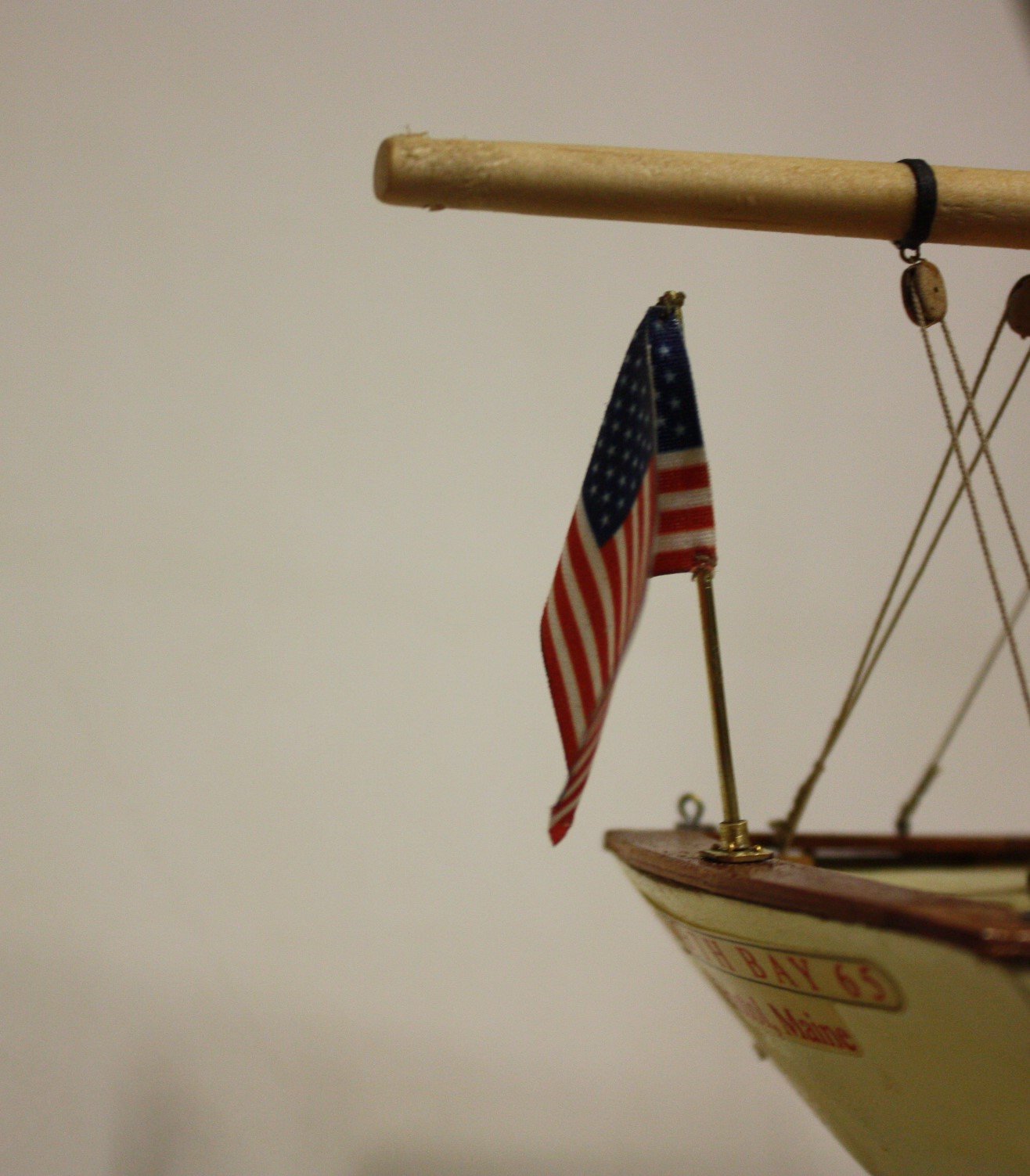
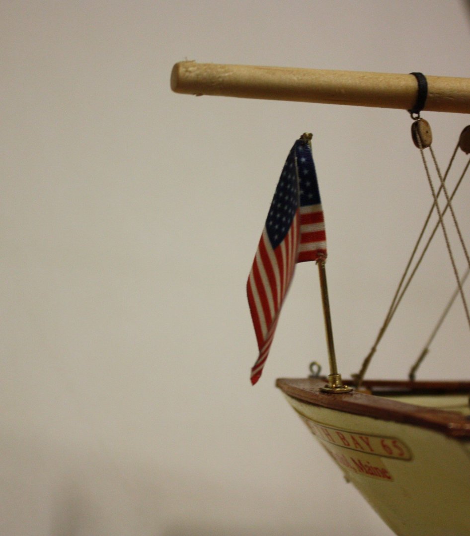
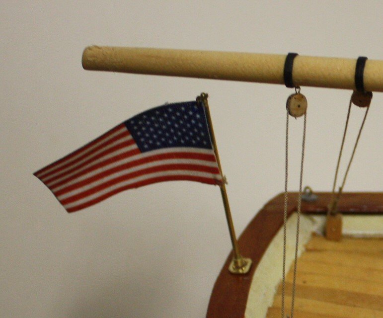
At the welcomed suggestion of one of our top model builder members, I adjusted the flag to hang down more naturally. I soaked it in situ with matte medium with a brush and hung a small clamp to pull it down until it dried. The matte medium is water proof and dries perfectly clear. I think the end result is more natural and looks better. Allan
-
Wood filler?
allanyed replied to Phalpenny's topic in Building, Framing, Planking and plating a ships hull and deck
Alan, Same idea but a LOT easier the way you and David do it. Thanks for the tip, a great help for many of us. Allan -
Wood filler?
allanyed replied to Phalpenny's topic in Building, Framing, Planking and plating a ships hull and deck
Welcome to MSW Peter/ There are choices here. Ideally, redo the planking so there are no gaps. Realistically, it could be very difficult to match the pearwood. You can try making a pile of saw dust with any pear wood that you may still have then make a putty of the sawdust and wood glue to fill the cracks. The finer the sawdust the better. You can quickly make a pile of saw dust with a thickness sander or even a hand held orbital sander. Even a sanding stick with a 220 or finer grit will work, just takes a little longer. It may not be exact, but might just be better and easier than trying to find a store bought filler that matches in color. Allan -
Welcome aboard Mike, very happy to have you join this crew. Now that you will have a couple kits under your belt, would love to see you become another member that takes the step over to the dark side and do a scratch build!! Allan
-
Thanks Pat! As much as I have enjoyed working on this model and have learned a LOT as there were a number of new things I have learned to do, I am anxious to finish and get going on finishing Ernestina for them. Will try to post in my old log on the Effie M. Morrissey/Ernestina once I get going on it again in the next month or two. More traditional old schooner and a heck of a lot more detailed information on rigging is available from Chappelle and others. Allan
-
Keith, I think most of us have run out of words to use on how beautiful your work is. Maybe monumental is still available, and if it is, that's my comment on your work for today's post. It is certainly an aspiration for 99.9% of us. Allan
-
Thanks Keith! I have had the walnut for what seems like forever and a long story that goes with it and the tree it came from, but that is for another day. I figured I may as well let it go to a paying customer and it does no good just sitting in the shop. Quick??? Not really. I have a loose deadline, but as I can work on it for at least 4 hours a day on most days, it goes pretty quickly. Allan
-
Ahh, she is bringing back memories. Great work so far!!! Allan
-
Well done, you are making great progress. Hope to see more soon. Allan
-
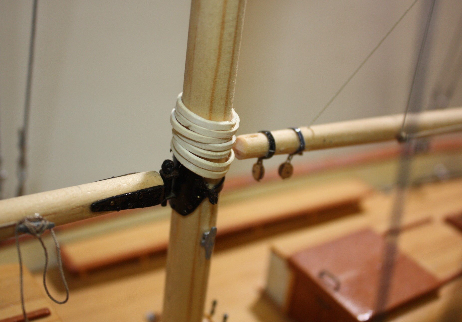
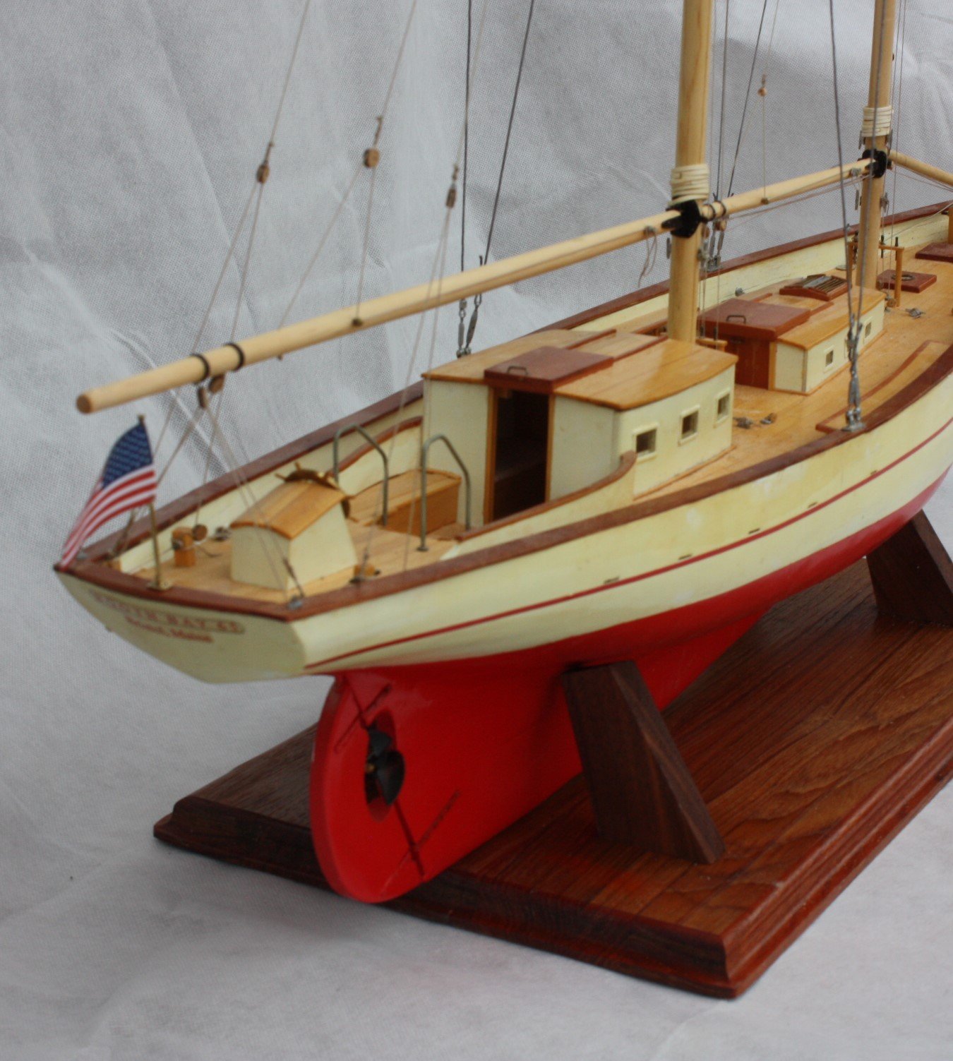
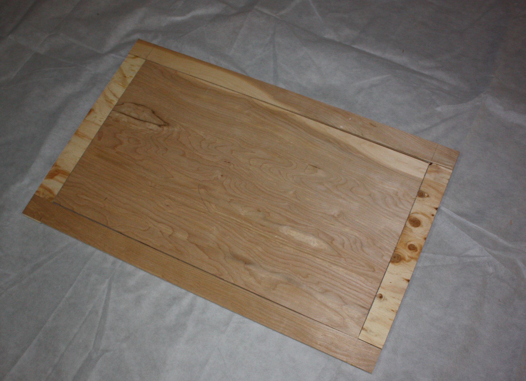
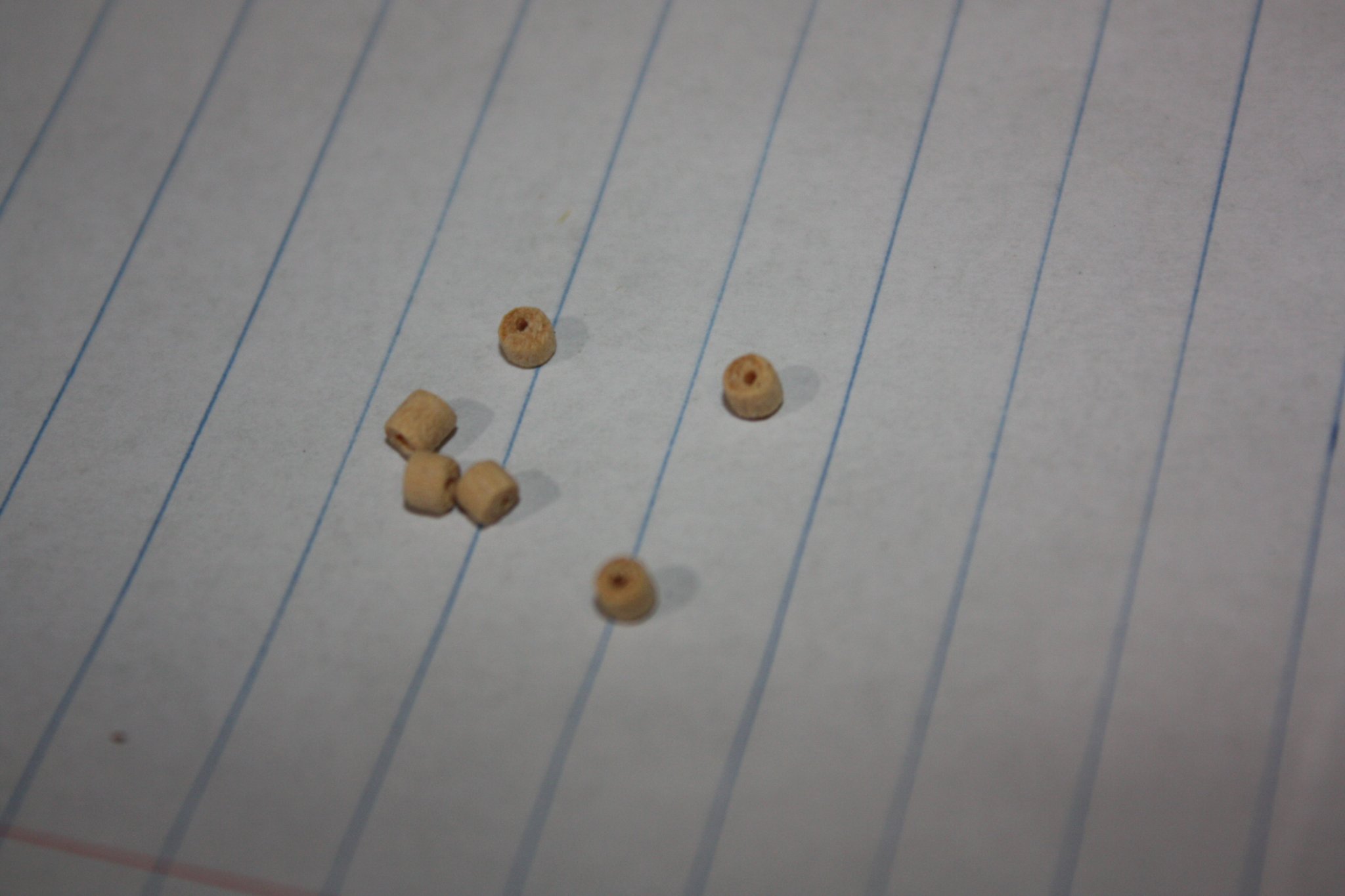
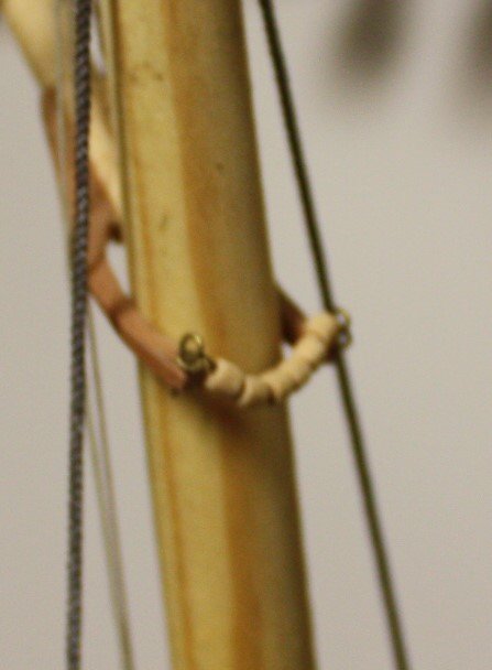
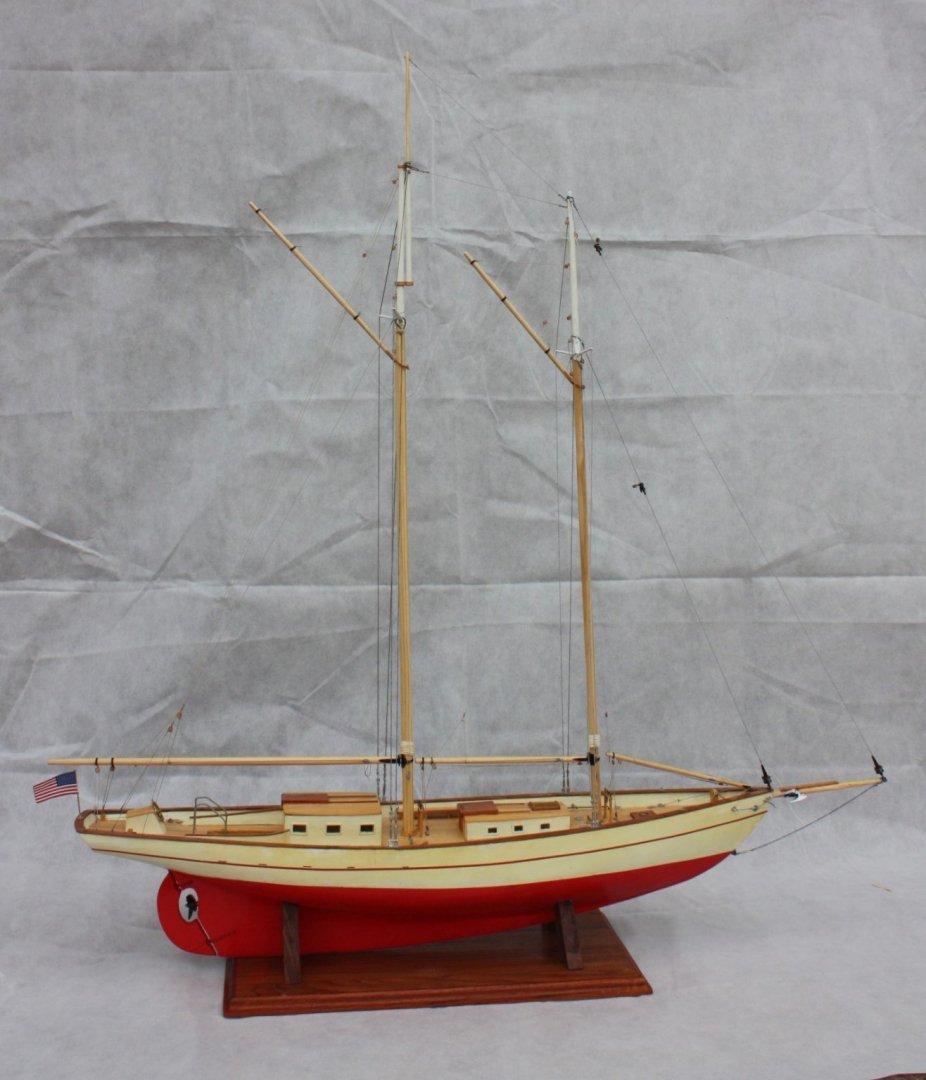
Standing rigging is about complete, including flying backstays which I suppose are more running rigging than standing rigging. I turned the parrels on the lathe using boxwood. I finally bought a block tumbler to round the edges of all the blocks and put the parrels into the tumbler for about 20 seconds to round the edges as well. Saved a lot of time hand sanding and came out more even. The parrels are supported on a metal (brass in this case) rod similar to those on many of the Gloucester fishing schooners rather than rope. The back drop material I used for some of the photos is not good. I usually like to use roll back drop paper which does not wrinkle and is easy to set up without a seam where it goes from horizontal to vertical. Another lesson learned and a wasted $15 I will never see again on the material I bought. The flag is cloth and the staff and support plate and sleeve are brass. I used brass nails in lieu of bolts, which at this size show relatively well. The fore and main boom guys or tackles have a hook on a single block as well as a double block. The plans show a single block at the end of the boom, but in looking at a lot of rigging plans for schooners, they invariably have a double block which makes sense when rigging in the unused mode and would work well when the booms are swung outboard. The photo showing the boom saddle also shows a single block on the fore boom before I replaced it with the double block. That was not fun as there was very little room to work. As suggested at MSW many times by many folks, I rig everything I can on masts, booms, and spars before fixing them in place. It is sooooo much easier to get it right. The base is walnut that I have had laying around and kept moving with us for 48 years. The model rests well on the cradles but I do not want to put hulls in the hull so will use threaded stock or perhaps brass rod with threaded ends between the cradles that will go through the base and into the keel. I was thinking of using Velcro on the cradles in lieu of the brass rods, but not sure these will be sufficiently secure for a truck ride of 1600 miles. If anyone has gone this or another route I would love your feedback. I made two frames and plugs for silk span sail making. The one in the photos is large enough for the main sail, but impractical for the small sails. This is my first time using this method so I made a smaller frame for the smaller sails and a practice run. Glad I did the practice run on a smaller size as it did not go very well. I am using the method David Antscherl describes in his sail making supplement to Volume IV of TFFM, but will be trying a few alternative ideas along the way. If they work out I will post once they are proven. Allan


-
Gaff sails and backstay rigging rules
allanyed replied to Michelnou's topic in Masting, rigging and sails
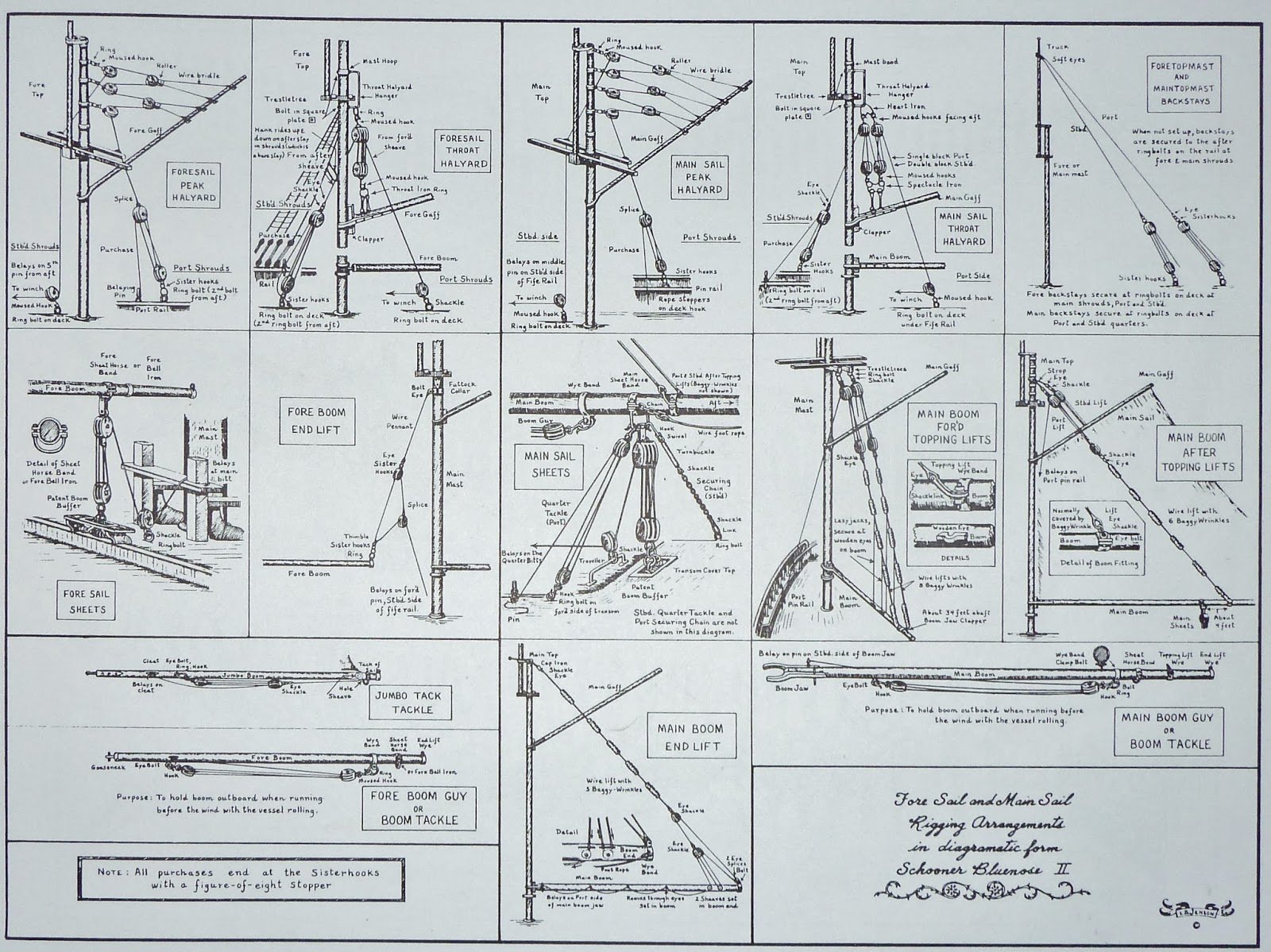
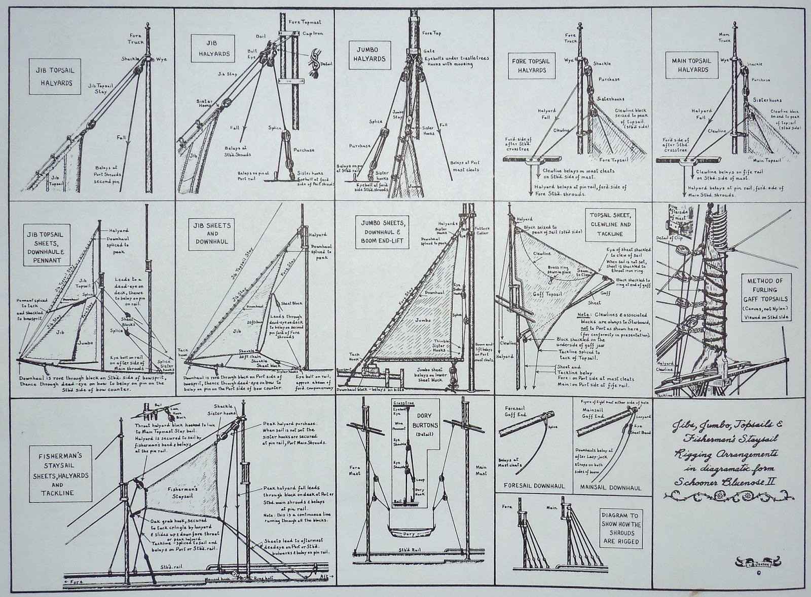
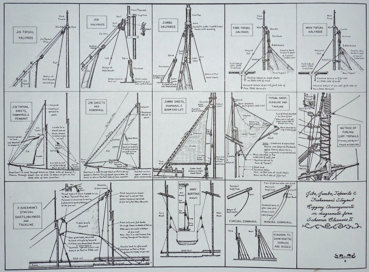
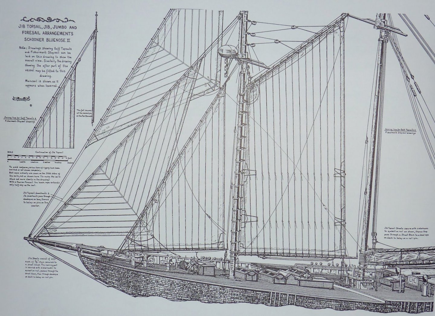
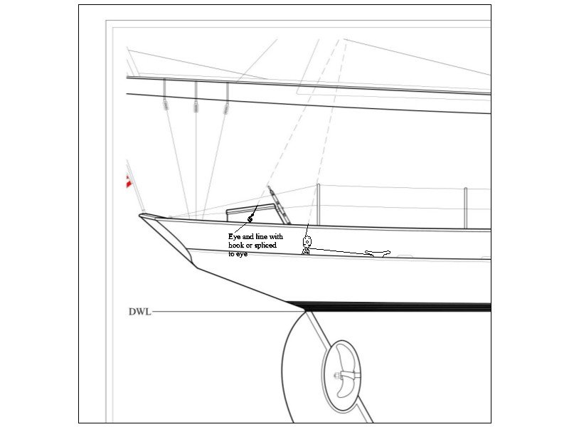
Michel, The attached first page is a sketch of the backstay rigging for a 65 foot schooner. Note that the block and cleat in this sketch are inboard. The eye is in the cap rail or alternatively may be secured to the deck. The next three pages by Jennison may help in much of your rigging. As Bob mentioned not all vessels were rigged the same. A great reference for schooners of the late 18th century is Chapelle's American Fishing Schooners. One caveat is that while this book is loaded with details, it has no useful index and I find myself scouring it every time I need to find a detail. The rigging subjects are "somewhat" in alphabetical order in the book but a pain in the neck to find anything quickly. On the plus side, I find every time I use it, I get a LITTLE more used to how he laid out the items. Allan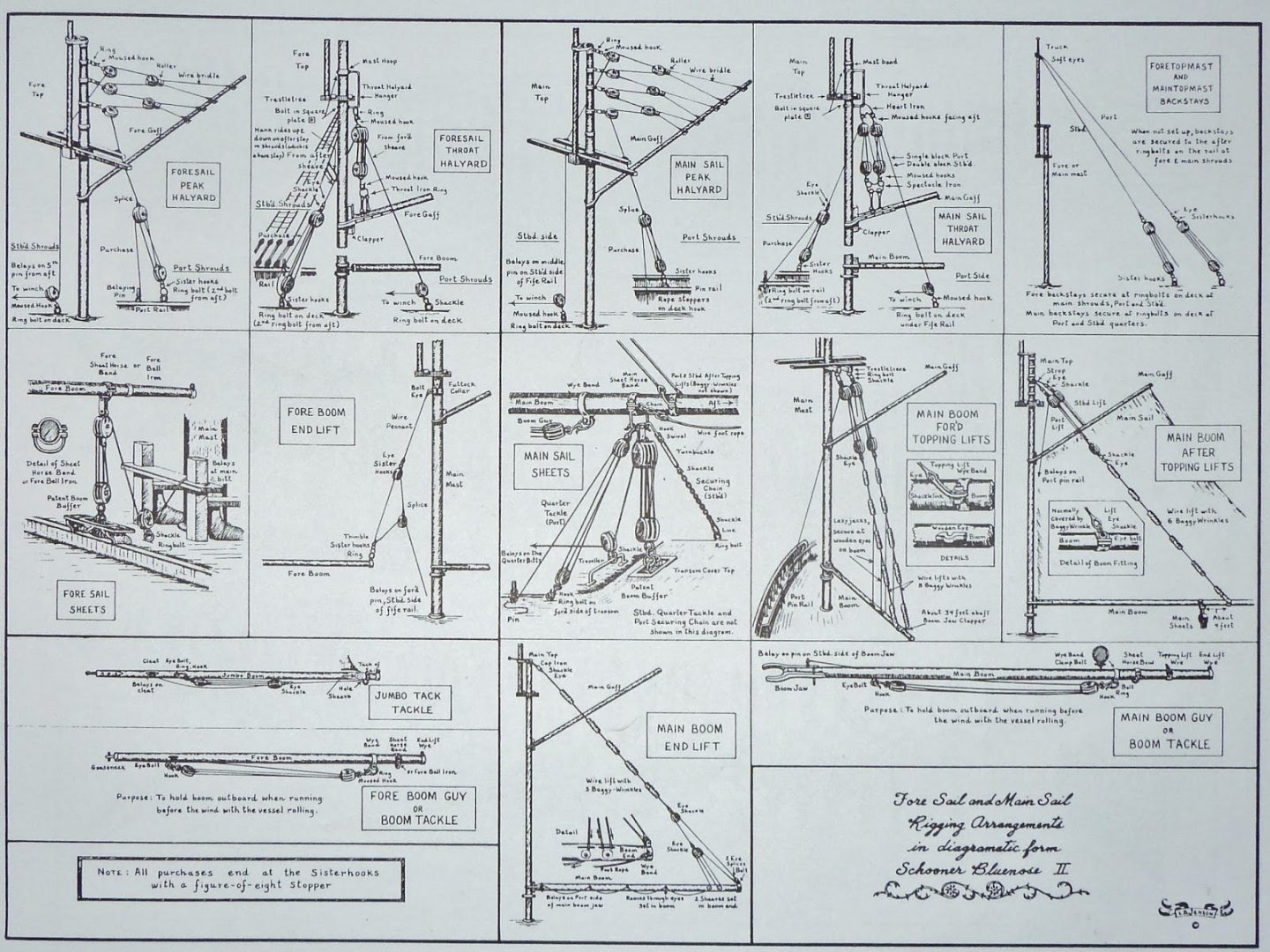
-
Gaff sails and backstay rigging rules
allanyed replied to Michelnou's topic in Masting, rigging and sails
For the main back stays, these are usually flying back stays that are set up with blocks to allow one side or the other to be "let go" in order to swing the boom. Allan
-
Druxey, ain't that the truth! As I mentioned previously, common sense has to come into play. For example, many of the blocks are secured on pads on the deck with corresponding cleat nearby to belay the line. BUT, not all. There are several blocks set up in this manner with no place to belay the lines. The "Captain" that I am working with at Bristol Marine has given me pretty much carte blanche in getting things right as I see them, including adding fife rails, but I worry about gross errors. There is one issue in particular that I hope to work out with the shipyard today, but if not I may post here to get some feedback from the membership. Allan
-
Hi Richard, My apologies but I think a few of us (me for sure) have no idea what your post means about extreme tension fiber and extreme compression fiber. When you say beam column thickness, do me mean the frames, and regarding thickness is it the sided or moulded dimension? To make things a little easier, what ship are you building, nationality, name, rate, year, etc? From the photos and your checking with Greg, it sounds like a Swan class sloop. If this is not the case, for British ships, there are several sources (The Establishments of 1719, 1745 and 1750, Shipbuilder's Repository 1788, and Steel's Elements of naval Architecture (1805) that give the sided (fore and aft) dimension as well as the moulded (in and out) dimensions of each futtock and the top timbers at the foot and head of each as well as at the gun ports in the case of Steel. The moulded dimension also varies slightly in some cases in the range of the quarter deck and forecastle . Better information is sometimes available from a contemporary contract for the ship you are building or a sister ship in her class. If this is of interest you can contact the National Archives in Kew and the RMG in Greenwich. Allan
-
Keith, you beat me to it. I noticed the Fanta can/support piece as I am a fan of their products. Not necessarily for health, but got to do something naughty now and then. Vaddoc, I am looking forward to continuing following your log!! Great start. This is the first time I have seen anyone gluing the patterns to both sides of a frame so another new trick to try. Allan
-
Keith, I read your latest post several times as there are quite few lessons in there. You really do have a great gift for finding reasonable solutions for what seem like daunting problems for the rest of us. Did you soft or silver solder the master pieces before slicing the individual cradles? Allan
-
Thanks Tom, One thing that I have found that is interesting is the rigging. Like days of old with contemporary drawings from the British and French going back 100 years or even 300 years, there is very little information on rigging and rigging scantlings for many types of vessels. Running rigging was often customized by the captain so nothing was set in stone and it appears that is still the case to a great extent today. Discussions with the shipyard have been helpful, but generally they suggest going with what makes sense based on other schooners as they have not yet finalized belay points or other items and the drawings that I have are not necessarily final. Common sense and practicality comes into play, but this can be frustrating at times as I am no expert when it comes to rigging. Great learning experience though 😄 Allan
-
Ernestina Morrissey by Jond - FINISHED - 1:48
allanyed replied to Jond's topic in - Build logs for subjects built 1851 - 1900
Jon, I really envy you being able to visit Ernestina and the shipyard in general. When we get through this pandemic, a visit to the Bristol Marine yard is on my bucket list! -
Hi Tom, Welcome aboard! I wonder if you are our first helicopter pilot/aviator!! Would love to hear more about that as our youngest son flew Blackhawks for 22 years before retiring. Allan
-
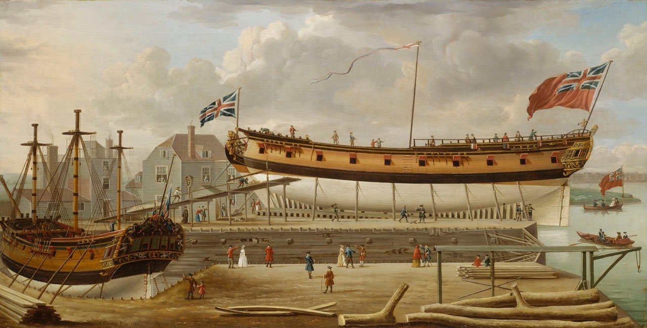
NMM had a beautiful model of a British shipyard on display some years back, but may very well be in storage. It was quite detailed and would answer a lot of questions to be sure. Maybe do a search on their website in the collections section. (https://collections.rmg.co.uk/collections) I did a quick look and there are a lot of paintings with worded descriptions to go with them. One example follows, including their written description. You also try Googling the name of an individual yard. I was able to find a lot of information on Buckler's Hard that way including a Google Earth shot of what she looks like today. Allan The exact location of the shipyard in this painting is unclear but it may be on the south bank of the Thames at Rotherhithe. The ship in the foreground ready for launching is a 24-gun sloop of war, much in use by the Navy for patrolling around coasts in peace and war, and there is another ship in dry-dock to the left under repair with only the lower masts standing. In the foreground to the right some tree trunks are piled ready for use for shipbuilding and behind them two figures sit on ready-sawn planks. In the right forergound there is a small capstan-powered crane overhanging the edge of the wharf. The inclusion of many figures informs the painting and the artist has chosen to include a variety of social types and activities at the dockyard. Several workmen can be seen working on scaffolding under the ship, and there are a number of figures on its deck. A small figure to the far right, which may be a child, appears to be balancing precariously on the rail, one hand on the ensign staff while the other waves a hat. A man to the left holds out his hand in a gesture of warning. Figures appear at all the upstairs windows of the building to the centre left, which may be the master shipwright's house. The sixth-rate is probably about to be launched and flies a Union jack at the bow, a naval pendant on a temporary midships flagmast and a red ensign at the stern. John Cleveley's principal profession was as a shipwright in the Royal Dockyard at Deptford. He did not become a professional painter until the late 1740s. He was an early exhibitor at the Free Society of Artists in London and two of his three sons, John Cleveley the Younger and his twin brother, Robert Cleveley also became painters after working in Deptford's Royal Dockyard. The painting has been signed by the artist and is dated 1758. Date made 1758 1758
-
Keith, I read your latest post several times as there are quite few lessons in there. You really do have a great gift for finding reasonable solutions for what seem like daunting problems for the rest of us. Allan
-
Epoxy paint?
allanyed replied to Patrick Matthews's topic in Painting, finishing and weathering products and techniques
I have no idea about epoxy paint except on garage floors so I am curious as well as to applications on models. I just looked up the 2K paint and see that it can be had in a spray form as well so could be interesting as well. Hope there are replies to your post based on personal experience. Allan -
Sorry to everyone back east...
allanyed replied to Patrick Matthews's topic in Modeling tools and Workshop Equipment
Patrick, Yeah back here in the East (Ave Maria, FL) the weather is not good. 85 degrees F, today so a sweaty day on the golf course. Life can be hard. Truth is that I miss a few things about the northeast such as the fall colors, nights on the town in Manhattan, the tree going up in Rockefeller Center, fishing for striped bass in the spring and fall in Raritan Bay and Sandy Hook, and a couple other things. Don't miss the high taxes, traffic, and a number of things, so a good trade off for us having moved down here. Allan