allanyed
-
Posts
8,149 -
Joined
-
Last visited
Content Type
Profiles
Forums
Gallery
Events
Everything posted by allanyed
-
Welcome to MSW from another Floridian Allan
-
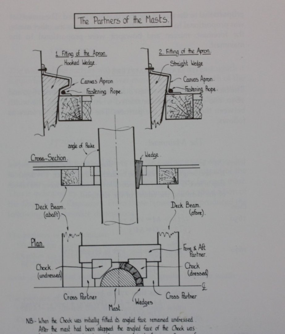
 There were wooden wedges between the mast and the partners. These were then often covered with canvas so you can just add a painted ring before you set the masts. Below is a sketch of a wedge ring that is actually just the ring and without the wedges going down and through the partners. They can be glued on top of the partners (or planking) as is. In reality the planking ends at the partners but this does not look possible on your model. The second picture is from Goodwin's The Construction and Fitting of English Ships of War. Allan
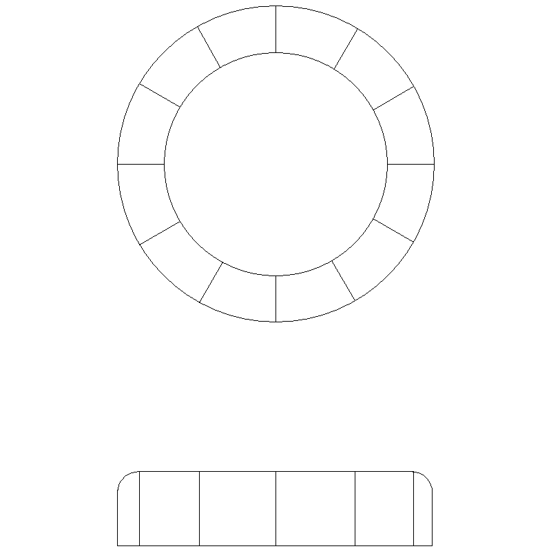
-
McMaster Carr for lots of stuff from high quality drill bits to copper and brass sheets and rods. https://www.mcmaster.com/ Allan
- 3,618 replies
-
- 3
-

-

-
- young america
- clipper
- (and 1 more)
-
Two valid points IMHO, but as the admins have what is sometimes a thankless job, like herding cats, adding to their load may not be such a good idea. When it is my time I will post my library if I can. If not, is there any rule that says my admiral or sons cannot post here if they log in on my member ID with what is going on and what is up for sale? I looked but cannot find any rule to the contrary. Allan
-
The lines of every piece are so precise it almost looks like a cad drawing. The care and attention to detail are clearly evident. Allan
-
Me too. Lot of work, but it gets the job done right, kudos!
-
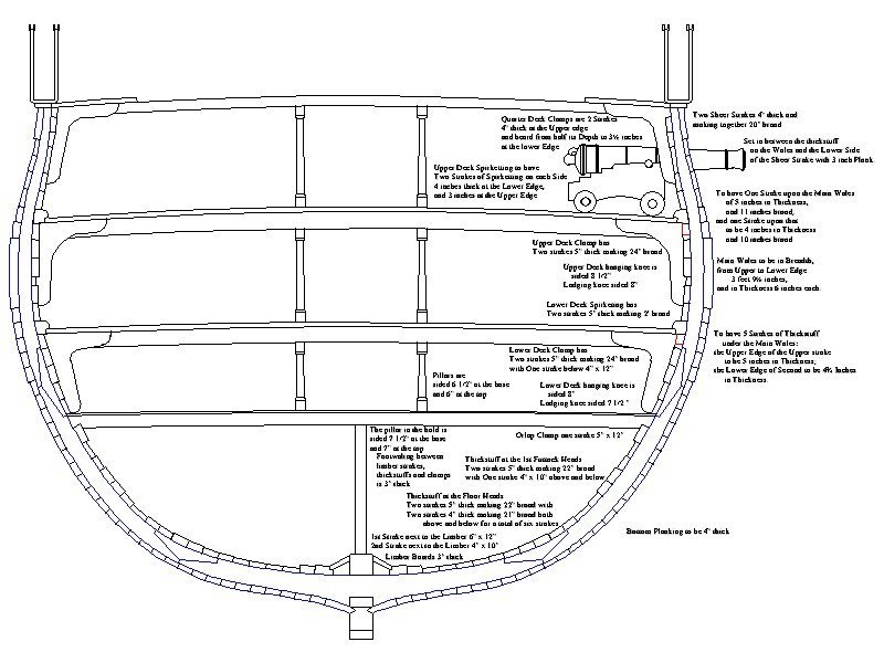
Hi Chuck, There were fore and aft longitudinals, or stringers, at the floor heads or at the first futtock heads below the water line outboard well below the wales. But internally I do not recall seeing these. Sorry if I am being obtuse or perhaps it is just nomenclature but I am only familiar with the spirketting, quickwork, sealing and clamps. The below is the Euryalus, 36 and might be helpful if it is terminology thing. Regarding the knees both the hanging knees and lodging knees fay to the deck beams and internal planking. Other than appropriate bolts that go through the hull planking, the you're correct that the knees themselves are not associated with the wales. The channel knees help support the channel chains and the main wale is to prevent hogging.
-
Go for it but have you considered that the material hugely out of scale and replace it with silk span? If not for this project, maybe the next one, consider buying the $5 booklet on sail making by David Antscherl at Seawatch Books. The sails are FAR more realistic and to scale. Allan
-
Sizzolo, The sail looks like a white ensign. Was a flag woven or painted on sails on the actual British ships? Guess they could not fly a false flag to fool the enemy with the sail giving them away. 😁 Either way it is a first for me
-
On the actual ships there were usually one and more often two frames that were in line with a gun port so there is nothing wrong with a frame crossing a port. The frames were cut and ledges put in place then the linings/stops on the bottom ledge and sides of the frames forming the fore and aft sides of the port. Allan
-
Hi Keith, This is an interesting point, but as there were main wales down low, middle wales on large rates and channel wales above, from what were they offering protection? Allan
-
I agree but I wonder how the sheer of the ship was actually determined. I imagine one reason the deck sheer was to be flat enough to avoid cannon tipping over if the sheer was too great and sea conditions were at their worst. I just starting looking at Steel in how the sheer line was actually determined. LOTS to read, and will hopefully not fall asleep in the middle of it. Allan
-
Do you recall the source of this statement that the wales were to support the knees? Could have been for a particular nation or era? Aside from who knows what was done on galleons, you can see thousands of contemporary plans and models that confirm your conclusion that the wales were to support the knees is not true. Another example below, Hercules (74) 1760. From Peter Goodwin's The Construction and Fitting of English Men of War, page 53, ISBN 0-87021-016-5: The wales were bands of heavy planking on each side of the ship between the waterline and the lower gundeck ports. The purpose of the strakes was to stiffen the hull fore and aft, in an attempt to overcome the problem of hogging......... the wales were not laid parallel to the gundeck. but to the designed sheer of the ship. Therefore, the gunports at the fore and after ends had to be cut into the upper edge of the <main> wale. He also goes on to describe when the wale was a split pair of strakes and when they were wide bands of four or three strakes. There is a more in his description including determining thickness, tapering near the bow He describes the channel wales as well. They are where the channel chains were secured, thus the need for heavier planking. Goodwin describes the middle wales on larger rates but does not give a reason for their presence. Allan
-
Very good point Eberhard. Warpipe WELCOME to MSW. Do post a little intro about yourself in the new members forum if you would be so kind. The masts are never a straight piece like a dowel rod. It is sometimes easier to use square stock and a plane and sand paper to get the right shape. Regardless, if you go with dowels they would still be tapered upwards and downwards from where they pass through the upper most deck. There are many drawings of masts and spars on the RMG collections site and some very high resolution versions on the Wikicommons site that will show you what masts actually look like if realism is a criterion for you. Most important is that this is after all a hobby for most so go with what makes you happy. Example from Deptford, 1780, that has measurements for masts for 44, 36, 32 and 28 guns ships as well as the drawings can be found at It is 99 mb so will not load here, sorry. The high resolution version can be found at 44 GUN SHIP RMG J7802.png Click on the 17,00 pixel version then you can flip it to see all the notes. Lower res version is below. For all ship sizes, including larger ships from circa 1800 there is a wealth of contemporary information that you can find in David Steel's Elements and Practice of Rigging https://maritime.org/doc/steel/ Mast making starts on page 18 and continues with a lot of detailed drawings to go with text and scantlings. Allan
-
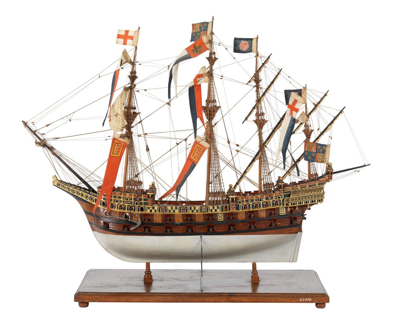
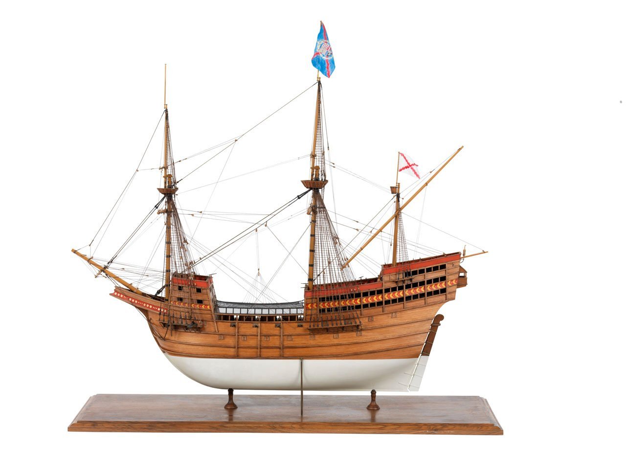
So simple yet brilliant. But, now I am questioning my own comments. Looking at galleon models at RMG (they are all modern (19th century and 20th century) the gun ports follow the sheer of the wales. Hmmmmm.......are these accurate or artists' licenses? Two examples are below of Great Harry (model made circa 1851) and a Spanish galleon created by James Lees and Philip Wride in 1988. Allan
-
Drafting Frames
allanyed replied to tmj's topic in Building, Framing, Planking and plating a ships hull and deck
That is the best line I have ever heard regarding our shipbuilding forefathers. Allan -
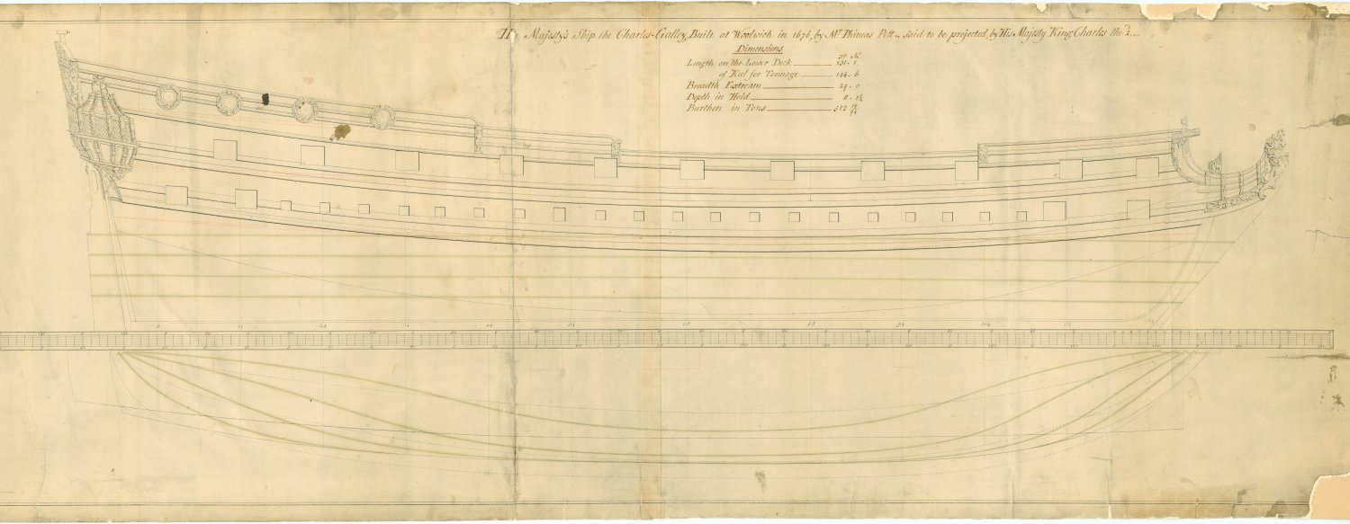
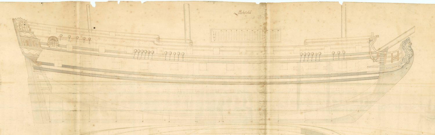
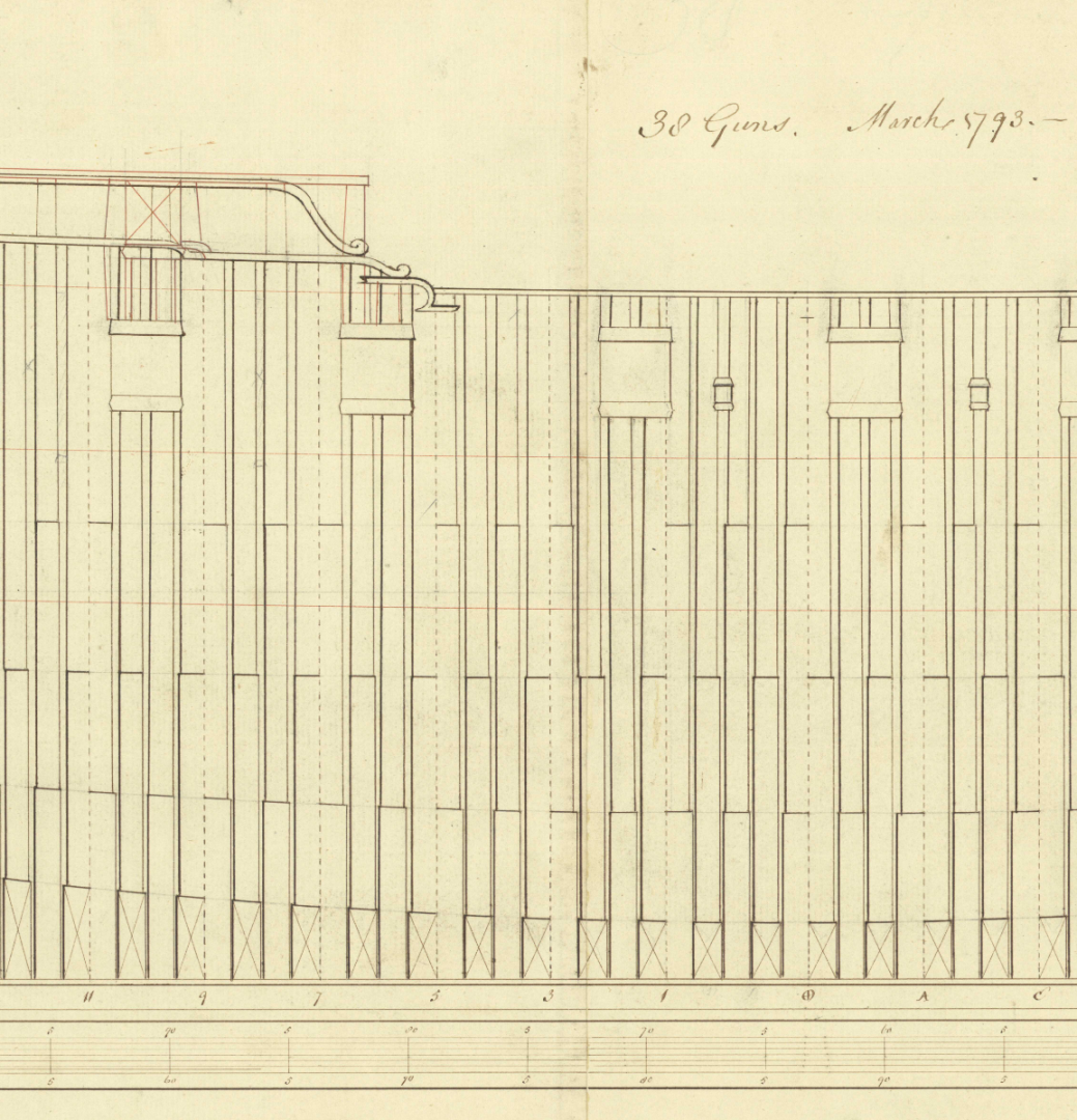
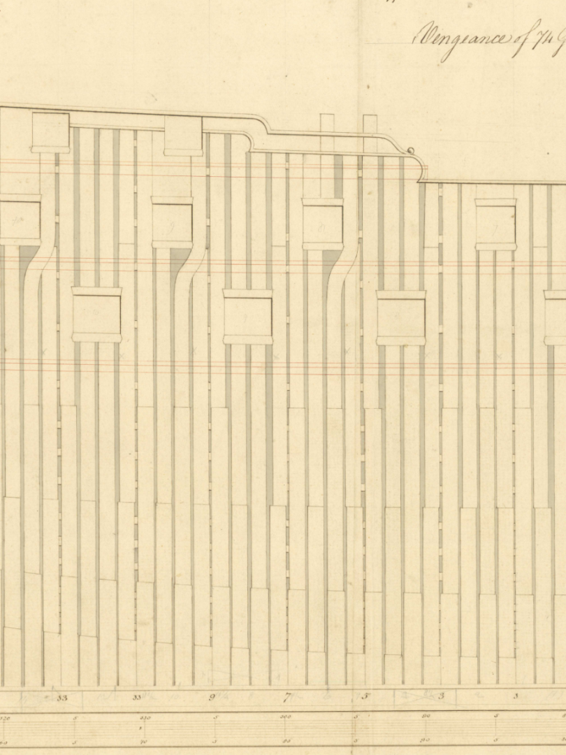
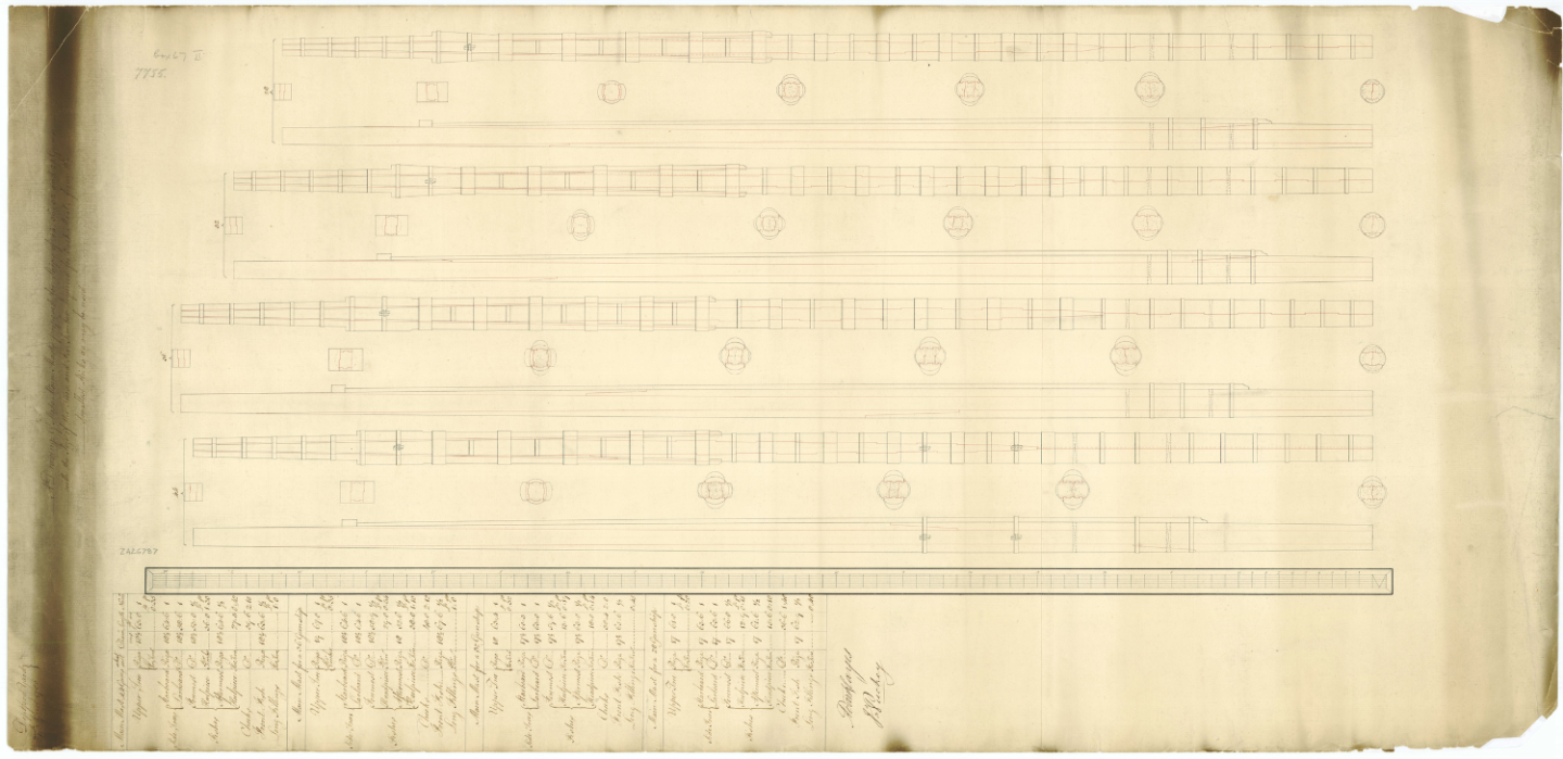
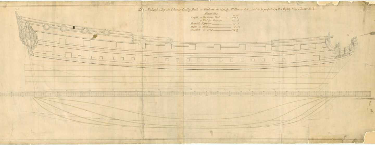
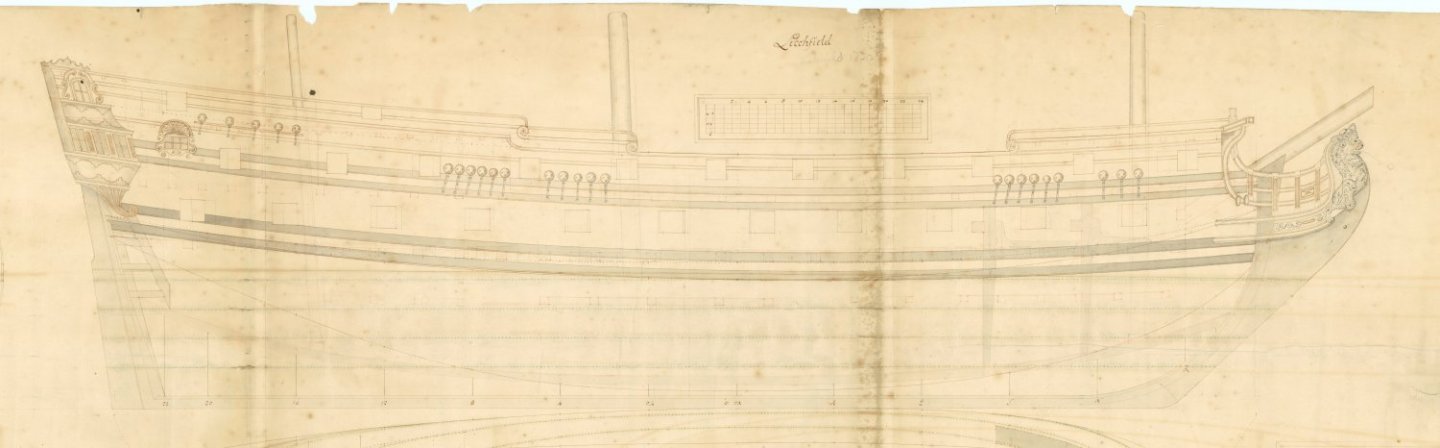
Hi Steven Thanks for posting the treatise. This will be my afternoon read today. Hi Gregory. Thank you for posting that planking expansion plan but it has no real baring on the wales and outboard planking. On the planking drawing that you posted note that there are no wales which struck me as odd then realized it is the inboard planking drawing from the RMG site, not the outboard so a completely different matter. With the deck beam clamps being part of the planking and dictating the location of deck beams it makes sense that the inboard planking would follow the sheer of the deck. On the drawings I posted, you can follow the line of the gun ports which we know must follow the line of the deck. You can see that the deck sheer has no relation to the sheer of the planking/wales. On the Litchfield drawing you can see the deck beams as well and again there is no relation of the sheer line of the decks to that of the planking. Of a more modern nature, Brilliant (36) 1757, it is more detailed and obvious in the below plan if you follow the wale and compare to the sheer of the deck you can see there is no relation between the run of planking and sheer lines of the decks. Again, I cannot speak of the sheer of the Santa Maria as I have never seen actual evidence one way or the other. Allan
_PROFILEINBOARDPROFILEANDBODYPLANRMG_J7939aftsection.thumb.png.84980f521e861ddd699139d6313a9761.png)
-
I cannot speak for the Santa Maria as there are no contemporary plans but I have never seen a contemporary plan where the planking follows the sheer of any deck so it is possible you got it right. Look at the attached and you can see this on the of plans the Charles Galley 1676 and Litchfield 1695 - (I know, much later than SM) You can see that the planking line is nothing like the sheer of the decks. Steven, ref: main wale on the Lomellina (sank 1516, probably built 1503) Can you share the source on this as it is different than anything I have seen in the past, so far, and I find it fascinating.
-
I THINK Eberhard (Wefalck) may be able to help you. PM him and hopefully he will have a contact for you Allan
-
Do you think this crazy idea is feasible?
allanyed replied to Ulises Victoria's topic in Wood ship model kits
Hi UV There are similarities in size and era of the two ships assuming you are talking about the Surprise, nee Unite captured in 1797 and the Enterprise of 1774. The idea seems like a fun project but I would use an additional source to confirm the rigging. The rigging on British ships changed a lot in 1794 so IF your Surprise plans are accurate they still may not be applicable to the rigging on Enterprise. For example. the length of the main mast was a proportion of the beam in 1773 but by 1794 it was a proportion of the EXTREME beam + lower deck. You can check all the dimensions using the Danny Vadas spread sheet in the Article database here at MSW. It is a match to Lees Masting and Rigging for the two eras of your ships so you can make a comparison of the two eras and your kit plans and go from there. Allan -
As mentioned above, go with silk span. There is no cloth in existence that is to scale for sails unless there is a material with a thread count (TC) over 2400 assuming you want to replicate rough canvas which has a TC of about 50. There is a booklet on making sails that you can purchase for $5 from Sea Watch books. https://seawatchbooks.com/products/swan-iv-sail-making-supplement-from-the-revised-and-expanded-edition-by-david-antscherl
-
For your next adventure, should it be from the mid 18th century or earlier, maybe study some of the photos of the fully rigged models on the RMG site for some ideas. Lees has belaying drawings for pre-pin ships as well that show where lines were belayed before pins came into use. Allan
-
Hi Rock A bit late, sorry, but are you sure there were belaying pins on this ship? The English Navy did not use them until about 200 years later than when the Golden Hind sailed so I would think they would never have been used on the GH. Allan
-
I have seen a couple modern day cross section models of Victory that show shelves in the hold like in the photo above but I cannot find any contemporary plans or contemporary models or other contemporary based information that shows/describes shelves in the hold in midships. If anyone can provide information on these based on contemporary sources I would be very interested to see this and would also like to know if these existed on other rates and if they were appropriate to a certain era. Many thanks Allan
-
VERY NEAT AND CLEAN WORK!!! The more I see your pics the more I am impressed with Vanguard AND your workmanship. Allan
- 648 replies
-
- 3
-
-
- Indefatigable
- Vanguard Models
- (and 1 more)


_PROFILEINBOARDPROFILEANDBODYPLANRMG_J7939aftsection.png.36df556f78ae0286af26af16f27c7d42.png)