allanyed
-
Posts
8,149 -
Joined
-
Last visited
Content Type
Profiles
Forums
Gallery
Events
Everything posted by allanyed
-
 Hi Patrick. Your desire for accuracy is to be commended. Your neatly done construction is also to be commended. The learning part of our hobby never ends which is a great thing for all of us. I realize that you are limited to what you received in the way of parts unless you want to change things on your own, aka, "kit bashing." If not for this particular boat, for future projects, look at the scantlings for any given boat or ship for that matter. If you look at the scantlings for this case, a 23 foot launch circa early 19th century, you will see why corrections are probably not possible at this point. Two examples are the frames and cap rail. At your scale the frames on this size boat should have a sided and moulded dimension of about 0.75mm (1.75"X1.75" full scale) at the top of the frames and there should be about 16 to 18 of them. Those in the photos appear to be sided and moulded about 3mm which would be about 7" or 400% oversized. These boats did not have a cap rail per se. If you look at the contemporary drawings from RMG Collections below it may help understand. In any case the full width with the upper most plank should be about 3mm not including the chock where as your materials give you something around 5 mm. Thank you for sharing your build. Allan
-
Hi Patrick The launch design is interesting. I think there may be a mistake in the kit as it shows three thwarts double banked and two thwarts with no oarlocks for any rowers at all. Based on contemporary plans a 23 foot launch typically had six thwarts and was usually single banked for six rowers. It may be too late for your boat, but for the future you might want to check out the build logs on the 23 foot launches here at MSW as well as plans at RMG Collections and on the Wiki Commons site. The following happen to be for the 23 foot launch found on the Bounty but they are appropriate for a wide range of years and are accurate. https://modelshipworld.com/topic/33539-23-foot-launch-by-allanyed-bounty-late-18th-century/ and https://modelshipworld.com/topic/33614-bounty-launch-by-imustbecrazy-116-small/ There are scantlings available for a wide range of boat types sizes available if that would be of interest to you for your other boats. Allan
-
I would think the shot was stored entirely in shot lockers below the platforms or orlop when not in battle. Seems they would have some shot brought up when called to quarters and the youngsters carried additional shot as needed. Allan
-
HMS Euryalus 1803 by rlb - 1:48 scale
allanyed replied to rlb's topic in - Build logs for subjects built 1801 - 1850
Kudos Ron, your build is a joy to follow!! Allan- 122 replies
-
- 2
-

-
- Euryalus
- Plank-on-frame
- (and 4 more)
-
Sounds like a good idea for a Dutch vessel. Just as an FYI garlands were supposed to be abolished on the bulwarks on British ships for the same reason as those around the hatches, to move the weight lower in the hull, thus affecting center of gravity and center of buoyancy. Cheers Allan
-
42ft Armed Longboat 1834 by Ainars - Ancre
allanyed replied to Ainars's topic in - Build logs for subjects built 1801 - 1850
Ainars Thanks for sharing, and welcome to MSW!! Are you from Latvia? Maybe post a little introduction in the new member section. 😀 Very interesting technique that you show. Is there a reason you did not cut the futtocks and floors out from a solid sheet rather than bend laminations? Allan- 12 replies
-
- 2
-
-
- Armed Longboat
- Ancre
- (and 1 more)
-
HMS Euryalus 1803 by rlb - 1:48 scale
allanyed replied to rlb's topic in - Build logs for subjects built 1801 - 1850
I cannot tell if you are doing this from the photos, but I like to print a second page for each frame and then set the pieces on the drawing and hold them down with scrap weights to be sure they are exactly right when gluing them together. (page 57 of volume 1) Allan- 122 replies
-
- 6
-
-
- Euryalus
- Plank-on-frame
- (and 4 more)
-
It depends on the time period. I cannot speak for the kit designs or Dutch ships, but, according to Peter Goodwin in The Construction and Fitting of English Ships of War, page 217, the British Admiralty ordered the abolition of the shot garlands in 1780. The king plank was on the center line, if there was one, and the binding strakes ran along the hatches. The binding strakes were the same width as the other deck planks but 1" to 1.5" thicker than the flat of the deck. but they were scored at the beams and let down so the top of the binding strakes were even with the surrounding planking. For modeling purposes, it is probably easiest to use the same thickness material for the binding strakes. Allan
-
Hi Jan, I agree with you there are often differences in many things on these vessels with era, nationality, etc. but from what I could find the gratings are similar in construction as well as the sizing of battens, ledges and openings I doubt the battens and ledges were ever a made of different size pieces with open ends. I may completely wrong about this so would love to see contemporary information to the contrary. ALWAYS happy to learn something new. 😀 Allan
-
Have you visited or contacted RMG about this? research@rmg.co.uk Allan
-
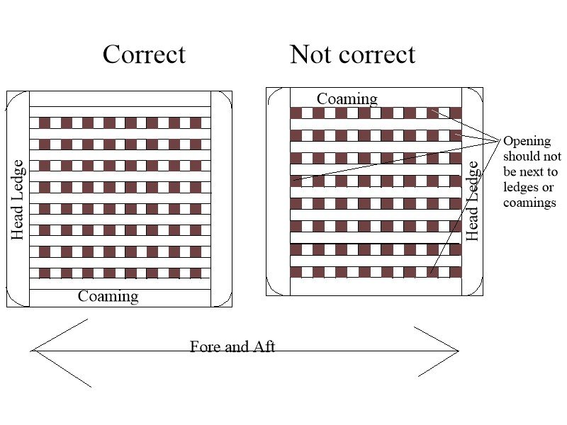
Hi Philip Keep in mind the gratings should never end with open spots against the head edges or coaming pieces. Sketch below might help. You can buy bundles of 1/32"X1/32" basswood strips pretty cheaply that will be close to your scale and each piece will be the same width and depth versus a different size for each strip. Allan
-
LOL. Thanks Druxey.
-
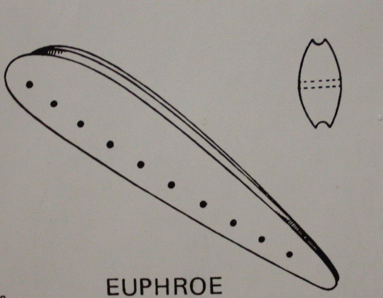
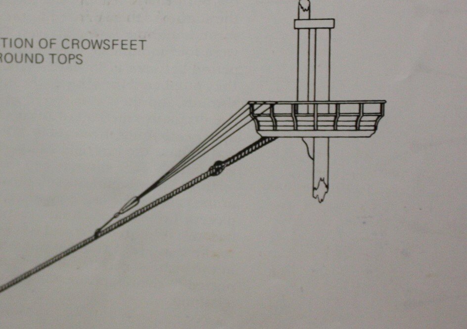
This is a euphroe and it is an easy piece to make. From Lees' Masting and Rigging page 44. The euphroe tackle comprised a single block stropped to the euphroe block and another block seized to the stay. The standing part of the fall was made fast to the upper block. The running part, after reeving through both blocks was either hitched to the stay below the lower block or was made fast round the tackle. Allan
-
Forming a rabbet
allanyed replied to DaveBaxt's topic in Building, Framing, Planking and plating a ships hull and deck
I lived with a few chisels up to about 1/4" for a long time, then after seeing a number of recommendations here at MSW, I bought a full set from Mihail in Russia. They are absolutely gorgeous and will last many lifetimes. The set includes 23 chisels and gouges in sizes from 0.5mm wide to 3.5mm wide. I have not been in contact for a long time, but the email I have for him: mihail.kirsanov@mail.ru See pic below. Allan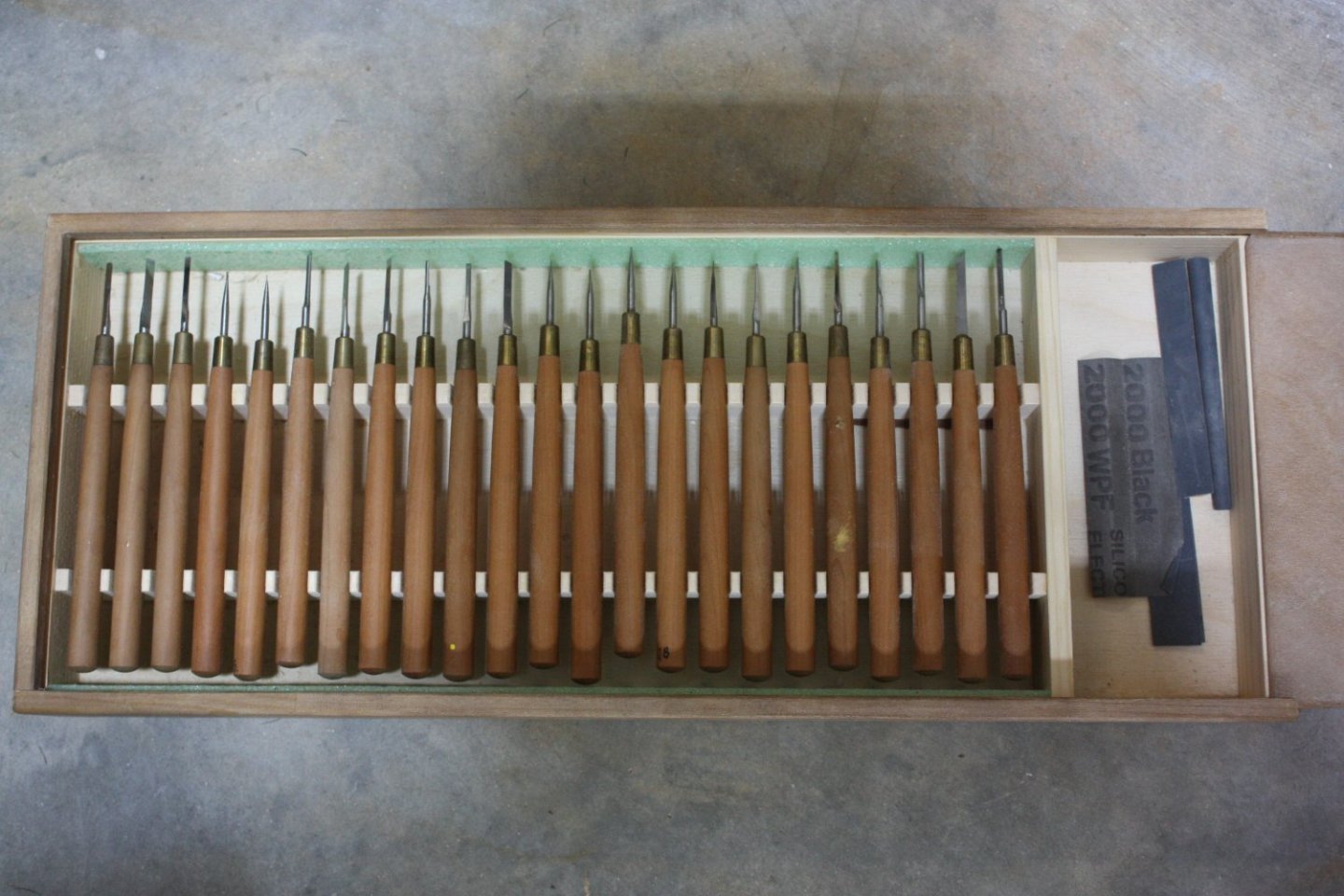
-
Tips for the Second-Time Model Builder
allanyed replied to Melissa T.'s topic in Wood ship model kits
Hi Melissa, I agree with the first sentence. 🙂 Just one more opinion, hope you don't mind, but I do not agree with the second sentence. I have rarely had a problem with PVA holding a piece in place after a minute with my fingers when there is no room for a clamp if the parts are shaped and fitted together properly, including planks. Allan -
Hi David, I am not sure I understand this David. The keel on a 38, based on the scantlings in David Steel in The Elements and Practice of Naval Architecture was 18 inches deep. Add to this the false keel which was 6 inches thick, this is about 0.38". The garboard was about 7 inches thick at the rabbet on a 38 but shaped to match the rabbet so took up closer to 5 inches. The copper would be paper thin at scale. This leaves over a 9/32" of keel exposed so I am not sure why there would be a problem holding the model on a building board or a clamp. Allan
-
Securing Ropes Wrapped Around Masts
allanyed replied to acaron41120's topic in Masting, rigging and sails
Hi Allen, From David Lees' Masting and Rigging page 2, "Wooden hoops were nailed to the mast at the top and the bottom of each woolding to serve as a protection and to help keep the wooldings in position on the mast." Allan -
Forming a rabbet
allanyed replied to DaveBaxt's topic in Building, Framing, Planking and plating a ships hull and deck
So true. The angle of the tool is fixed, but the angle of the rabbet is dynamic. The only place where it remains the same for more than one frame is in the dead flat. The angle change at the bow is a lot, but at the stern it is even more so. Chisels are my preferred method as my set from Mihail goes down to 0.5mm. Allan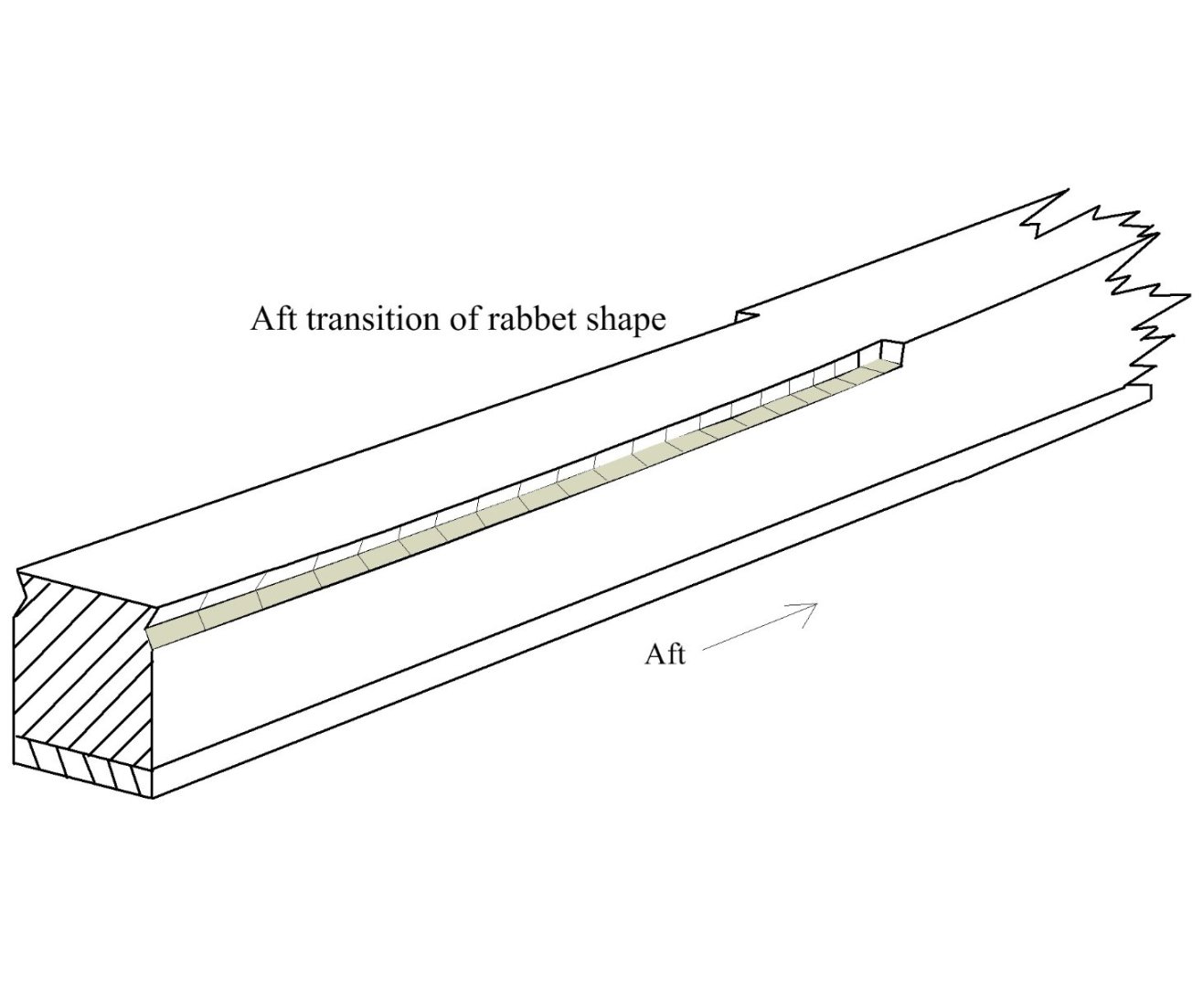
-
Druxey Great tip, thank you. Do you know if yellow ochre tubed artist paint would work as well? Allan
-
Some members hopefully will find the following article to be fascinating. Even small things like limber holes in the frames where they cross the keel made the article an interesting read. https://www.academia.edu/11506189/Frames_Futtocks_and_a_Fistful_of_Coins_the_Final_Report_of_the_Corolla_Wreck_North_Carolinas_Oldest_Exposed_Shipwreck?email_work_card=title Allan
- 1 reply
-
- 3
-
-
Henry, as you are talking about silver soldering, you may be relegated to using a high temp flame. I have used high temperature melt point silver solder pastes with different melt points for multipart assemblies and will continue to do so IF the parts are large enough not to melt in the process. For small delicate parts I have gone to Solder-It a low temp silver solder paste and a soldering iron and delighted with the results and ease of use. Allan.
-
Hi Mark She really is a pretty old thing! Probably just me, but your photos of the vessel and the line itself looks like a scale model, not a full sized yacht that you mention. Large scale to be sure, but it looks to be more or less 1 meter long as you mention. Assuming the 1.5mm diameter line you show would be about 2.5 inches in circumference at full size (20mm dia), the scale seems to be about 1:12 not 1:1. Still, an interesting model that you are lucky to have. Allan
-
Welcome aboard MSW I hope you will share some of your sea stories from living aboard for 12 years! Allan
-
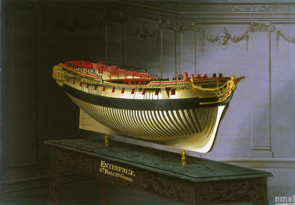
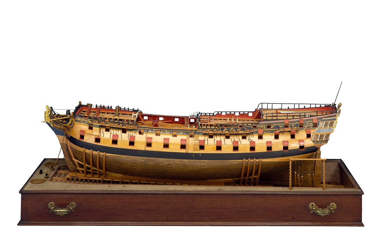
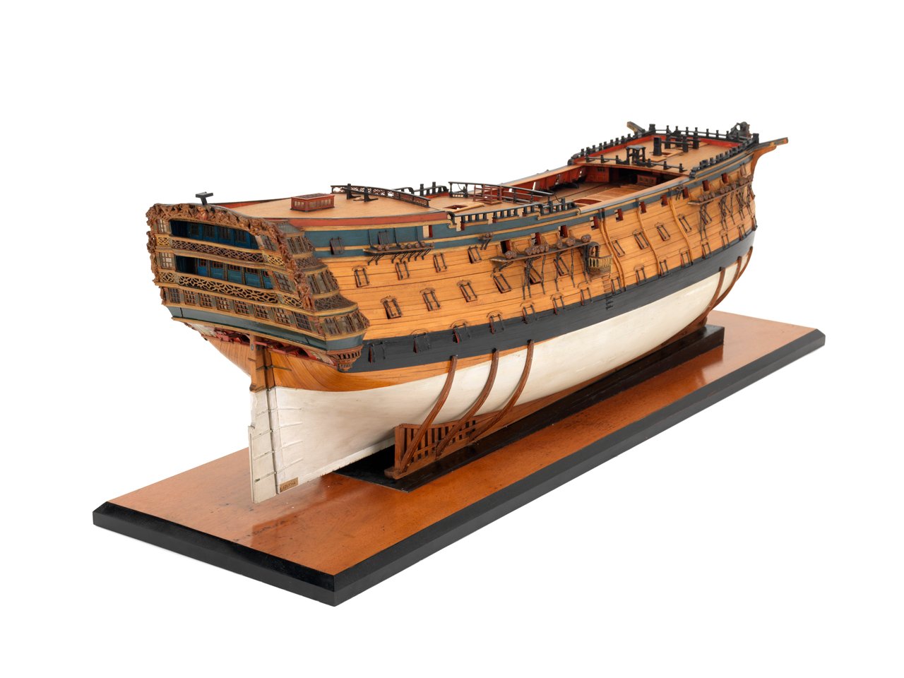
Welcome to MSW Giuseppe! I believe this kit is an Admiralty style model, not rigged. Some folks show the mast stubs which I think your kit provides, but most contemporary Admiralty style models do not have them. Some samples below. Allan
-
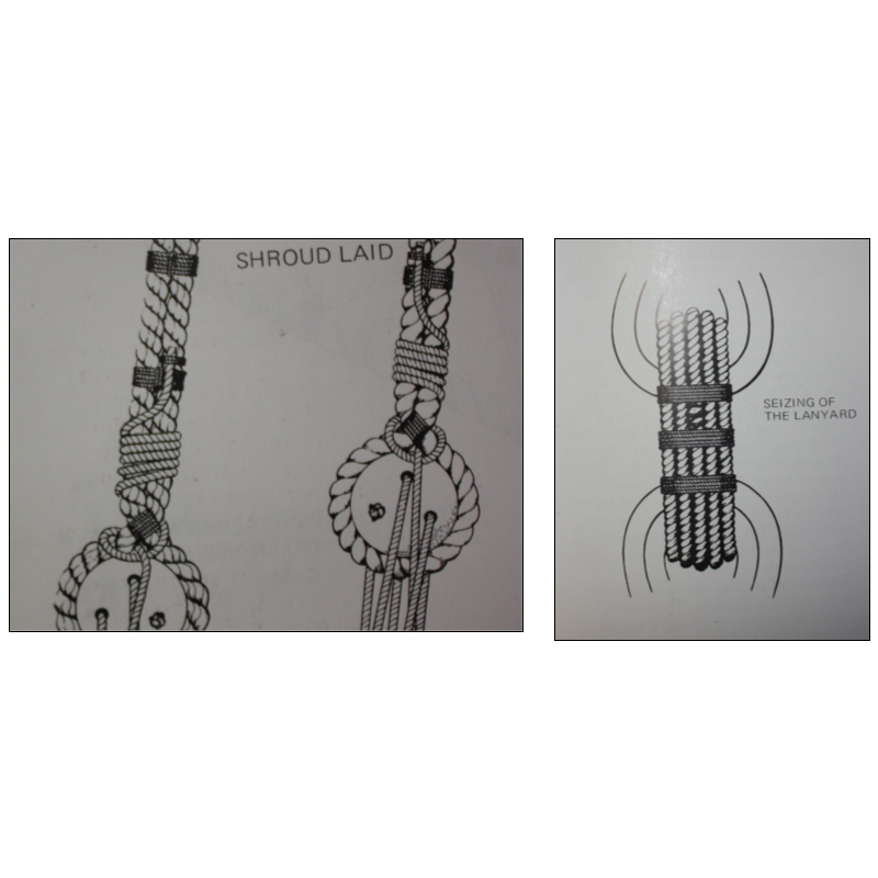
Great question, and I hope someone has an answer. Looking at the below drawings from David Lees' Masting and Rigging book the seizings look to be between 0.16 and 0.20 times the diameter of the shroud that is being seized which is right in line with the figure Grant gives, but I can find nothing on the circumferences of serving line. Allan