allanyed
-
Posts
8,149 -
Joined
-
Last visited
Content Type
Profiles
Forums
Gallery
Events
Everything posted by allanyed
-

3D printed homes.
allanyed replied to allanyed's topic in CAD and 3D Modelling/Drafting Plans with Software
Kevin I was taught to look at the MDH number on a car door jam before buying it, That plus the year it was built can be used to see what day of the week as well as the hour it came off the line so you could avoid a car built on a Monday morning (hangover car) or Friday afternoon, (getting ready to party car) Of course robotics supposedly have made such a worry nonsense, but.......... Allan -
Thanks Kevin, this is really well presented. Now for some aspirin as my head hurts. 😁 Allan
-
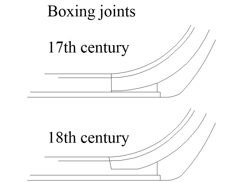
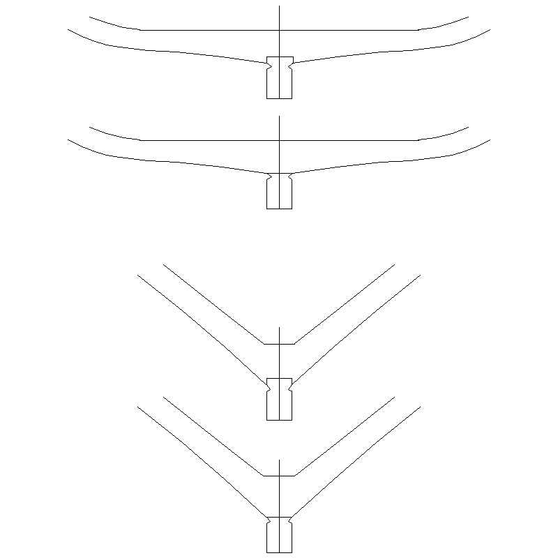
Look at the planking expansion I posted in post #5 above. It is not an exact science, but the main thing is that you do not take the garboard too high up the stem. The kit joint seems to be located where the boxing joint would be but I wonder why they designed it to be upside down. Then again I doubt many people will notice. 😁
-
https://www.bloomberg.com/features/2023-3d-printed-houses-austin-texas/ What's next?
-
Your shroud sizes are spot on. Regarding the ratlines the 0.25mm is closer to scale but as you say, the clove hitches may look too big. Try a couple and see which looks best to your eye. When it comes to rigging, the consensus seems to be that too small is better than too large, but half the size may be pushing it. I look forward to seeing the results. Allan
-
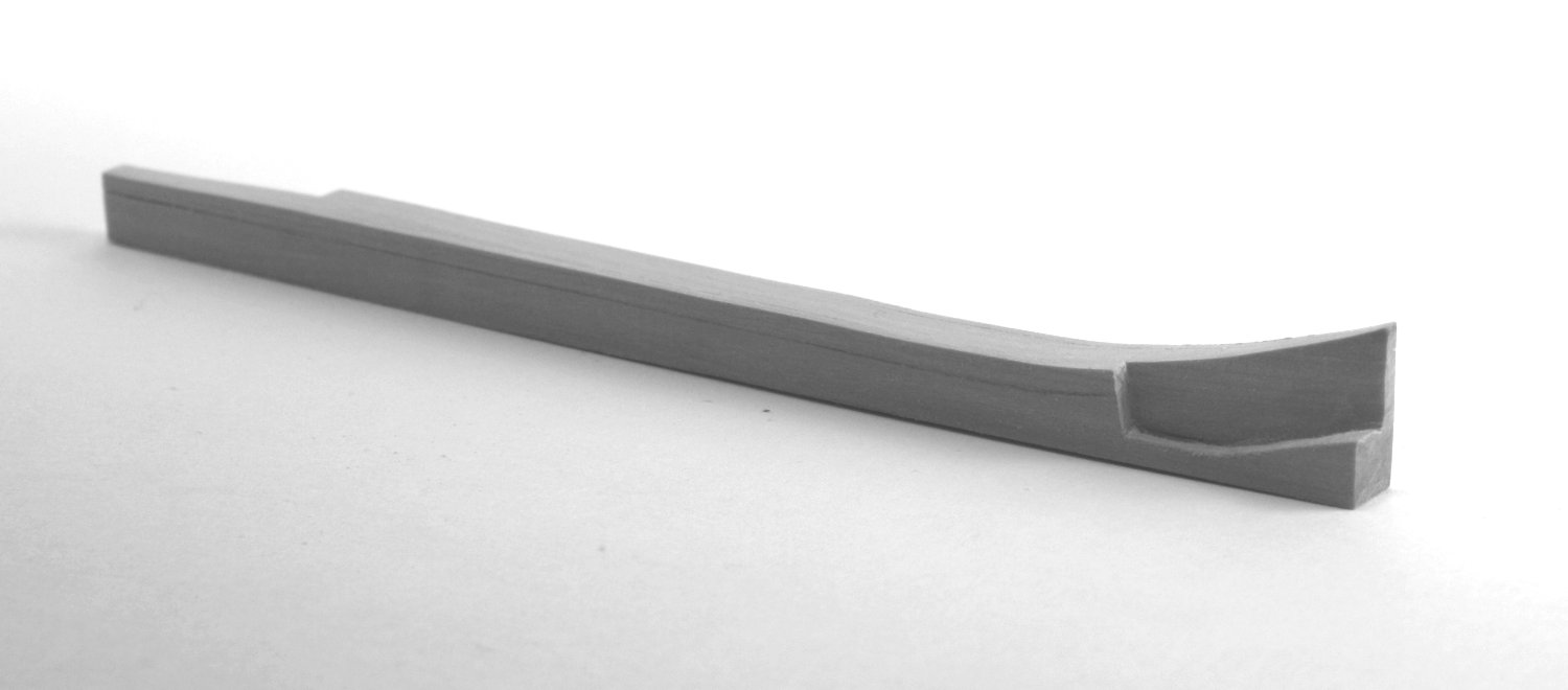
The boxing (AKA boxsum) is where the keel attaches to the stem. I don't know if any kits bother with this as most seem to use a simpler join. It varied a bit over the years, and was often coaked but for modeling purposes, if you decide to make a boxing joint, the coaking is not really needed as it will be hidden. The finished joint typically also received 6 bolts running horizontally,

-
Hi Jaager, This is a very interesting paragraph. I just spent an hour researching the life span of a resin printed object and found a lot of opinions but no statistics based on actual tests, be they accelerated or real time. It does seem to be important that the object has minimal (none is best) exposure to UV light and/or it should be protected with a UV blocker coating. In simple terms, many are of the opinion that they will last as long as other types of plastic. FWIW 3D printing has been around for a little over 40 years now. Not a huge history, but older than the internet🙂 I wonder, would the same degradation problem apply to items made of casting resin rather than printing resin? This is a really important consideration in terms of parts turning to powder on our models. I would hate to see someone use printed items and wake up a few years from now and find little piles of powder on their model. Allan
-
Dave, If the ratline and shroud circumferences are to-scale, they will probably look fine. There is a tendency to use oversize material for the ratlines which will then yield fat knots. From Lees' Masting and Rigging page 186, ratlines were a specific circumference 1 1/2" . This is just under 1/2 inch diameter and is regardless of the ship and era., If your scale is 1:60 the ratlines should be 0.008" (0.2mm) in diameter. It is easy enough to wrap your ratline material around a rod to see how many wraps there are in a cm or inch. If it is to 1:60 scale there should be about 125 wraps in an inch or about 50 wraps in a centimeter. Fewer than that, the line is too fat and the knots will look oversized. The shroud sizes varied with the size of mast so smaller shrouds and the one and only size ratlines will have a different look than larger shrouds with the same specified size ratlines. In the case of your current build, what is the diameter of your main mast shrouds? Using Lees' formulas for that size ship and era and a scale of 1:60 I came up with about 0.94mm diameter for the main mast shrouds. (Don't trust my math without double checking on your own 😀) Allan
-
I'm thinking about the strake that snubs into the rabbet Rudy Every strake snubs into the rabbet (except if there is a drop strake), but it sounds like maybe you are talking about the garboard strake. The width of the garboard strake is the same as the others so if they are all the same it makes no difference if you work up or down. The most common mistake made with the garboard is having it too long and riding up the stem well past where the boxing joint of the keel and stem is located. Look at a couple planking expansion plans to get an idea on how the garboard as well as the other planking lays. There are several on the RMG Collections site. One example: https://www.rmg.co.uk/collections/objects/rmgc-object-81960 Allan
-
Hi Rudy Not sure I understand why there a difference? If the distance along the frame or bulkhead in question with a tick strip is 3.8 inches for examples, it is the same if measured from the top of the rabbet up or from the sheer line down to the rabbet. Either way, if it is 3.8 inches to be planked and there are to be 18 strakes, the width of the planks at that frame or bulkhead should be 0.21 inches wide. Maybe post a pic if I am way off base on understanding your question. Allan
-
Hi Robert, The keel does have a rabbet as well as the sternpost and stem as usual. I was just pointing out that while there is a vee shape on the forward and aft frames, they still have a flat bottom to rest on the keel, with or without the mortice. Half frames of course are a different story, both fore and aft. In the case of POB instead of POF, there is a notch in the bulkhead, but the bottom would rest on a bearding line or steps at or above the rabbet. Allan
-
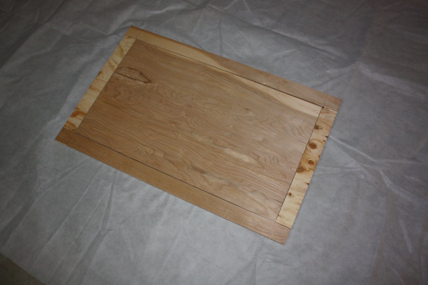
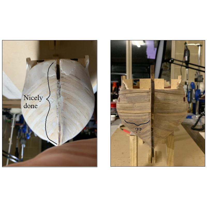
You first planking layer was done really well and is similar to how the actual ships were planked. All the strakes look to end at the rabbet as they should. A little tapering of the planks from the dead flat to the stem would have helped a bit but overall looks great. Is there a reason you did not do this for the second layer? Picture below to see what I mean. Thanks. Allan
-
Your planking looks superior. The fact that you lined off the frames, tapered the strakes and had each land at the rabbet is fantastic. If you are getting some planks that rise up due to edge bending, and you are not already doing so, pre-bend them with heat and it will be even easier. If you have not seen it before, check out the four part video by Chuck Passaro on the advantages of pre-bending the planks. https://modelshipworld.com/topic/22975-chuck-passaros-planking-videos-where-are-they/ Great looking kit and build, thanks for sharing. Allan
-
I totally agree that this booklet is excellent and for $5, cannot be beat. I made two frames so I can make small sheets on which to draw the sails once the material is painted and a bigger frame for larger scales. Silk span is cheap, and high quality paint is a bit pricey, but I urge you to not use the cheap bottled paints. Allan
-
Hi Robert, I am pretty sure the top of the keel and the bottom of the frames should be flat along the length of the vessel. While the hull shape becomes more of a vee forward and aft of the dead flat, the bottoms of the frames are still flat or mortised. Allan
-
I would add to what Roger suggests that you have a plug that fits inside the frame he describes. When you go to paint the silk span the color you want the sails to be, using good quality tubed acrylic artist paints (unbleached white titanium with a little yellow ochre and burnt sienna works well,) it will sag and stick to the table top or bench or whatever it is resting on. The plug will prevent the sag and keep keep the paint off your work surface. Once painted remove the plug and prop it up so the wet span is not sticking to anything. Do not let it dry on the plug. The span will retighten as the paint dries. Allan

-
I am not sure if the cleats would have been iron or wood during your time period so iron painted black may be more appropriate. Nice work and thanks for sharing your build. Allan
- 218 replies
-
- 1
-

-
- Victory
- Caldercraft
- (and 1 more)
-
Very neatly rigged ratlines! It may be my crappy color vision, but the cleats look like they are silver and tied with monofilament rather than wood with hemp rope. I am probably missing something on this, but curious none-the-less. Allan
- 218 replies
-
- 1
-
-
- Victory
- Caldercraft
- (and 1 more)
-
For the future, try to use battens that are about the same width as they are thick. The edge bending will be minimal and overall easier to use. It will also be easier to taper the planks to their proper width, especially from the dead flat to the bow, if you mark the line of each plank on at least every other bulkhead. With accurate tapering they will all land at the rabbet as they should, rather than coming up short as seen on many of the build logs. Allan
-
Hi Wade, Welcome to MSW! I checked out a couple minutes of his videos and they look to be nicely done. The figures you give are pretty close to the sources given in posts #2 and #3 so that at your scale of 1:168 any differences probably would not be noticed at all. How will you determine the sizes for all of the other standing rigging and all of the running rigging lines? Allan
- 19 replies
-
- 1
-
-
- running rigging
- standing rigging
- (and 1 more)
-
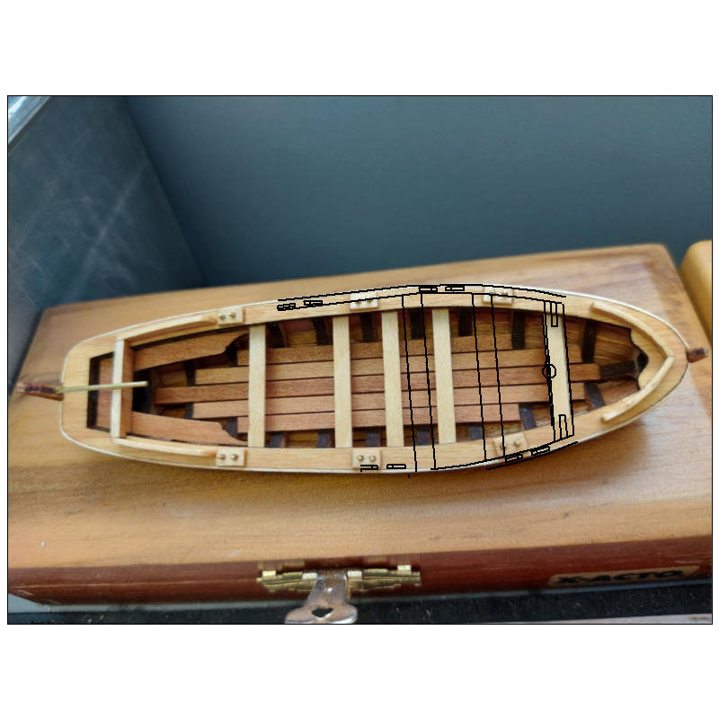
It's a hobby and it's your build so you should do anything that makes you happy 😀. My only question with this arrangement is where do the rowers sit? The space between thwarts was typically 22 to 23 inches. For your center thwarts there is only about 15 inches so no room for a rower to do his job. Also note the distance between the aft edge of the thwart and then center line of the thole. Below I superimposed a contemporary plan layout of a 23 foot launch on your model as a picture and a 1000 words, &c. Allan
-
Shaving down planks
allanyed replied to rudybob's topic in Building, Framing, Planking and plating a ships hull and deck
Not if you are spiling the plank. Look at the article on planking here at MSW in the articles database by David Antscherl. https://thenrg.org/resources/Documents/articles/APrimerOnPlanking.pdf If you are edge setting the planks, working on one side as Richard suggests could very well be a better way to go. Allan -
That is a great idea Masa. Thanks for the clarification. Allan
-
Welcome to MSW Przemek Allan
-
Maybe I am missing something, but what is the purpose of adding grain at our most common ship model scales? If oak or elm or pine or other woods used in ship building could be reduced in scale, the grain would barely show up, if at all, so most model builders look for wood with little or no grain such Castello, Alaskan cedar, bass, holly, pear, &c. Why would anyone want to add grain when wood with little or no grain is the goal to begin with? Allan