allanyed
-
Posts
8,149 -
Joined
-
Last visited
Content Type
Profiles
Forums
Gallery
Events
Everything posted by allanyed
-

Stays & Preventer stays top or bottom 1761
allanyed replied to DaveBaxt's topic in Masting, rigging and sails
You're welcome Dave, As I suspect you have found as well, many of us find that the research can be as much fun and as gratifying as the build itself. Allan -
3D cannon barrels
allanyed replied to allanyed's topic in CAD and 3D Modelling/Drafting Plans with Software
Most likely the 1760 Armstrong pattern as in your earlier link. Allan -
3D cannon barrels
allanyed replied to allanyed's topic in CAD and 3D Modelling/Drafting Plans with Software
Hi Tim, What ship/era/nationality is this for? If the RN, keep in mind that there were at least three Armstrong patterns in the 18th century starting about 1720 with redesigns in 1742 and 1760. The Blomefield pattern gun came into use about 1787 so the design you choose may be somewhat dependent on when in the 18th century you are aiming for. Allan -
Stays & Preventer stays top or bottom 1761
allanyed replied to DaveBaxt's topic in Masting, rigging and sails
In photos of various ships on the RMG Collections site, both the fore preventer stay and main preventer stay are on top of the stays and attached to the masts with attendant crows feet added to protect the stays from chafing from the sails. Two examples: https://www.rmg.co.uk/collections/objects/rmgc-object-66415 and https://www.rmg.co.uk/collections/objects/rmgc-object-66189 I would guess this is more likely than the fore mast stays being done differently than the main mast stays, but one never knows. Allan -
Welcome to MSW Doug, Are you speaking of European boxwood or castello boxwood, which is a wonderful wood with which to work? Take Bob's post seriously. If you're going to be painting the hull, consider something like poplar or basswood. I predominantly use castello boxwood for period ships that are not painted, but for schooners and such that will be painted, it is not necessary to go to the expense if you don't want to. As to figuring the amount of lumber, look at the amount of space from keel to the top of the futtocks at midships. Multiply times the length, then double it to cover port and starboard. Add another 20% for mistakes and waste if buying planks. In the long run I agree with Bob in that it is better to buy billets of timber and cutting it to size. The waste in sawdust is high but it is the same for anyone supplying finished planking so you will be paying for the wood plus the labor that goes into it. It only takes a few models to get your money back on a good saw and thickness sander with the savings. If you are not sure, calculate what you need then price billets versus pre-cut planking. You can then figure the return on investment on the equipment. Boxwood, be it European or castello, is getting more difficult to find. When my stock runs out may be looking at Alaskan cedar billets as well. BTW, Castello is not really a true boxwood but it really is super to work with. Allan
-
It actually might be easier to take out the piece and make a new one. Your call of course, but just a thought. Many of us like to use posterboard stock which is pretty stiff or even the cardboard on the back of a tablet to make a template then go from there. Saves a lot of shaping and do-overs. Allan
-
Welcome to MSW Joe. Please do post a little introduction about yourself in the new member forum. Again, welcome to MSW!!! Allan
-
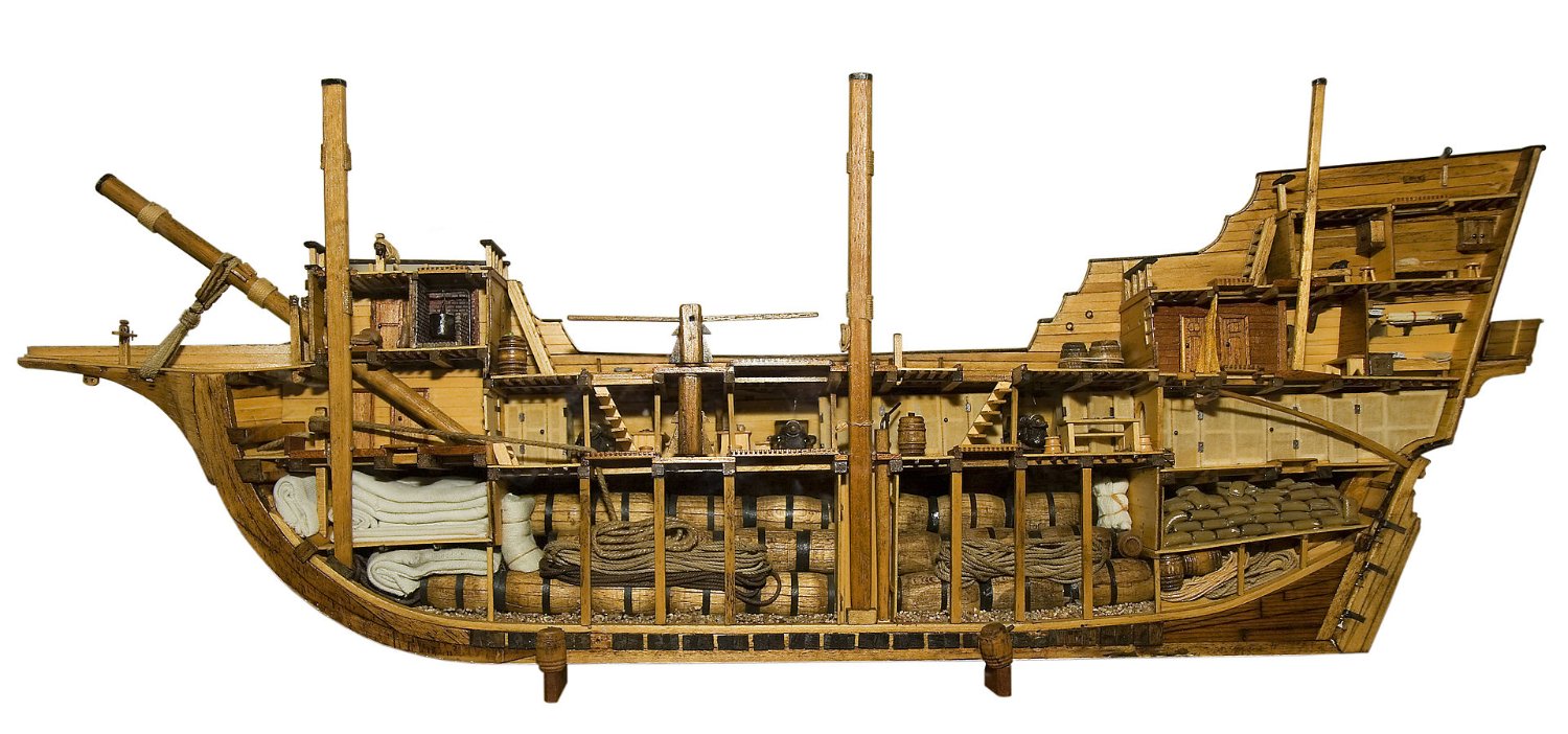
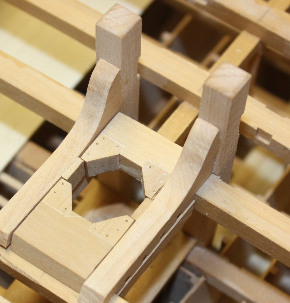
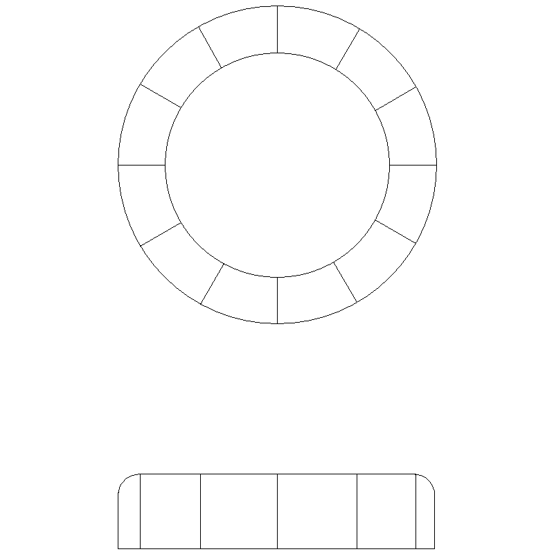
It seems like you are referring to the wedges. It is not a ring, but individual wedges that are inserted into the partners and will stand proud of the deck by several inches. This ring of wedges is often covered with tarred canvas or other means. Assuming you are not exposing any framing you can fake the top of the ring of covered wedges with a solid ring that would stick up above the deck about 0.08 inches more or less at your scale. Photos of the partners and a sketch of faked wedges follow that may make more sense than words. Allan Partners Wedges
-
CYA is rampant. Look at pharma ads for examples. It takes longer to rattle off the side effects than the benefit. Don, Regarding the subject at hand, how large are the gaps? As mentioned above, sawdust and pva work well. One quick way is to fill the gap (if small) with pva and hit it with an orbital mouse or similar. Sorry to bring this up, but as you are adding strakes, if there is a large gap, remove the plank before gluing it in place and re-shape it or replace it with a new one that has been properly pre-shaped as shown in the planking tutorial by David Antscherl in the Articles data base here at MSW (https://thenrg.org/resources/Documents/articles/APrimerOnPlanking.pdf) or shown in Chuck Passaro's four part video on how to pre-shape the planks with heated edge bending Part one --> https://www.youtube.com/watch?v=KCWooJ1o3cM Both methods yield properly planked hulls without gaps. Allan
-
EURYALUS 1803 by Peter6172 - 1:48
allanyed replied to Peter6172's topic in - Build logs for subjects built 1801 - 1850
You are absolutely correct about this. I do find that SHARP chisels make short work of the bevel on the futtocks and chocks compared to using files. Of course, in the end, whatever works for you is the way to go. There are 8 pages of text and drawings on making these joints that are EXTREMELY helpful in volume I of The Fully Framed Model by David Antscherl. Allan -
Mayflower by tj456 - 1/19 scale
allanyed replied to tj456's topic in - Build logs for subjects built 1501 - 1750
Such a huge model is a marvel to me and such a great opportunity for detailing. Congrats on taking up the challenge! Regarding your comment on the Constitution, normally it is a not usually a good idea to use a ship of one nation from 1600 as prototypical to one from another nation from 1800 without researching each item first. The differences are vast. Just as the shape of the hull and the scantlings changed continually, the rigging styles and items changed in size, shape and methods of belaying changed continually as well. For example, we often we see modern ship models with belaying pins when there should be few or none at all for that type and era of ship. If you have a chance to study David Lee's book on rigging, you will see that he shows many changes of rigging from 1625 to 1860 for British ships alone. R.C. Anderson's on rigging book would also be useful as it is mainly for the 17th century. Regarding the shroud rigging, the lower deadeyes sat differently on the channels. The support that ran from the deadeye down to the hull was flat iron until about 1720 when two or three long links plus a strap came into use. I do not recall ever seeing small linked chain like in the photo in post #7 above but perhaps someone else has. Slots in the outer edges of the channels on British ships was not introduced until 1771. Prior to that, there were square holes in the channels set back from the edge. There are photos of models including those of the Mayflower and the Prince Royal (1610) at Royal Museum Greenwich Collections website that you might find helpful even though they are not contemporary built. https://www.rmg.co.uk/collections/objects Allan -
Mayflower by tj456 - 1/19 scale
allanyed replied to tj456's topic in - Build logs for subjects built 1501 - 1750
About when did the deadeyes go from triangular in shape to round? Allan -
Craig, Great high resolution plan, thanks for the link. Do you know what year this particular Rattle Snake was launched? Thanks Allan
-
Thanks for the feedback. I do wonder how laser cut 1/32 plywood would hold up for these stern and gallery lights. Allan
-
This thread got me doing some digging and there was reference to the fluyt like shape, but none claimed she was Dutch built. Everything indicates she was English built but I thought looking depictions as well as Mayflower II, the layouts might have some similarities to the fluyt plans. As there is no contemporary information on the details being discussed the fluyt layout idea may be completely off base,........ or not. Sorry for causing any confusion. 😀
-
Allen There are four Dutch maritime museums that I found with a quick search on-line that may be of help if you contact them regarding your project for a Dutch fluyt such as the Mayflower. Allan
-
Patrick Just tuned in and will be following your build. Your research and follow up attention to detail is commendable. Thanks for sharing your work with us. Allan
-
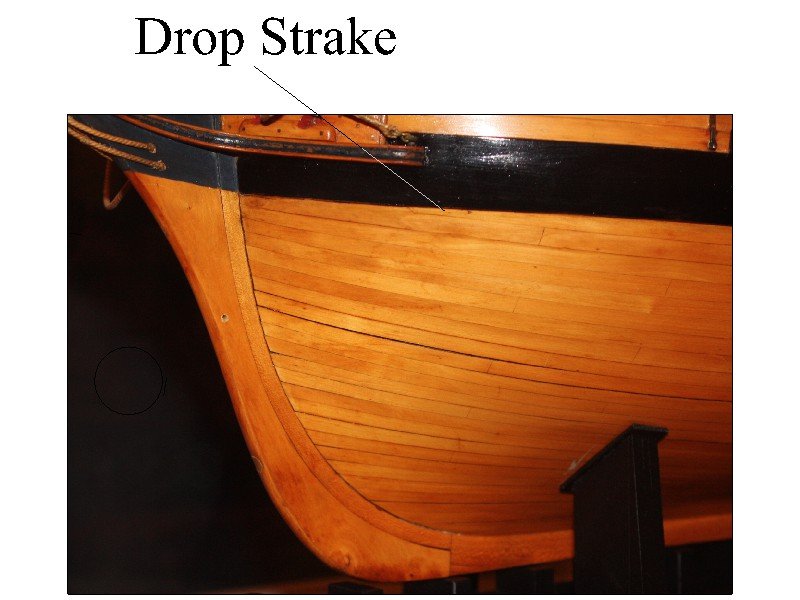
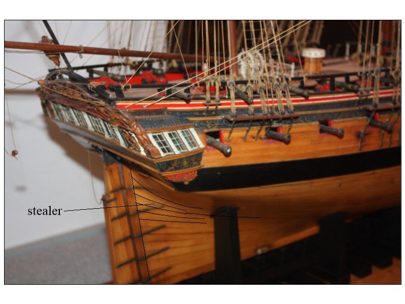
Drop strake can be seen below the wale Stealer aft
-
If you or a friend have a scanner on your printer, you can scan the images and print on label paper and use these instead of tracing. Quick and easy. Allan
-
Ain't that the truth!!! I imagine more would get into it, but no doubt investment in space and tools can be a major issue. Then again, for tools, add up the cost of 3 or 4 high quality kits and this would get a nice little shop going.
-
Hi Malcolm Really lovely work overall. Those laser cut lights in the last photo look nice. Is the material wood, plywood, or something else? What is the thickness wood sheet from which it is cut? The reason I ask is that maybe time for me to look for a local laser cutting person to give this a try. Thanks Allan
-
Welcome to the fray!! Allan
-
There are a lot of drawings of Dutch fluyts on the internet. I have no idea as to the accuracy including the one below. Allan

-
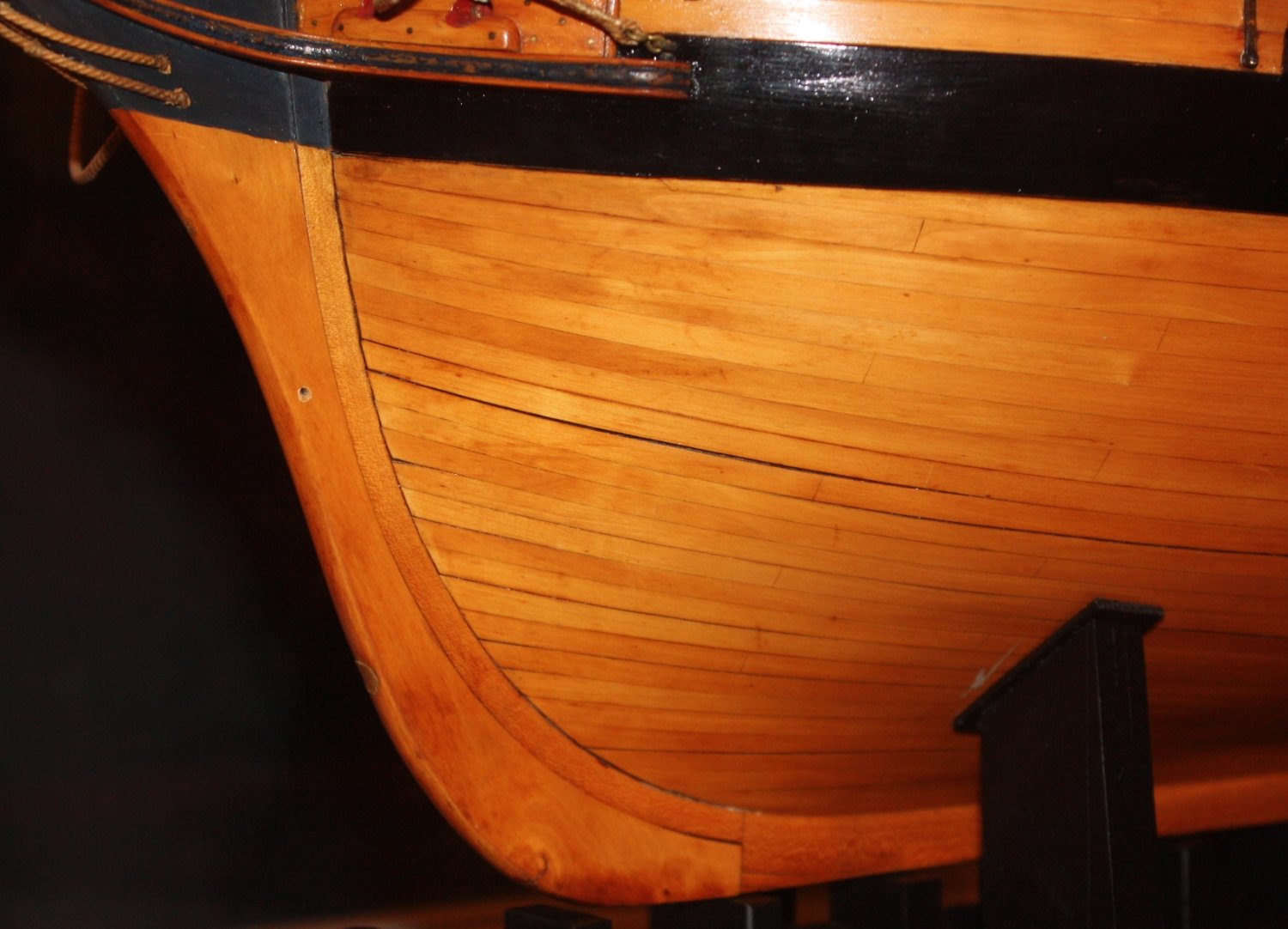
Hi Scotty Glad to see you started the build log. I really appreciate the story behind it and that you picked up the model to see it through to the end! For the future...... consider studying the hull planking tutorial in the articles data base by David Antscherl here at MSW and the four part YouTube videos on planking by Chuck Passaro. You can find them it on-line and in an old post here at MSW https://modelshipworld.com/topic/22975-chuck-passaros-planking-videos-where-are-they/. Rather than go into a long explanation, compare the results of two photos below. In the lower pic, note how all planks are tapered to nearly half their widest point and end at the rabbet. Again, this is something to consider for the future. If your model has two layers of planking, you may want to give it a try for the outer layer. It takes most of us a bunch of do-overs but gets easier with experience. Allan

- 59 replies
-
- 3
-

-
- Swift
- Artesania Latina
- (and 1 more)