allanyed
-
Posts
8,149 -
Joined
-
Last visited
Content Type
Profiles
Forums
Gallery
Events
Everything posted by allanyed
-
Welcome aboard Andrew. THANK YOU for sharing your story with us. Allan
-
 Just joined the fun on your log. WELL DONE! I just watched Season 2 Episode 1 of Combat Ships on The History Channel which was about Viking ships. They get right down to actually making planks without saws and making iron nails as was done in the 9th century. Well worth the watch for anyone that gets this channel. Allan
- 75 replies
-
- 1
-

-
- Oseberg
- Billing Boats
- (and 1 more)
-
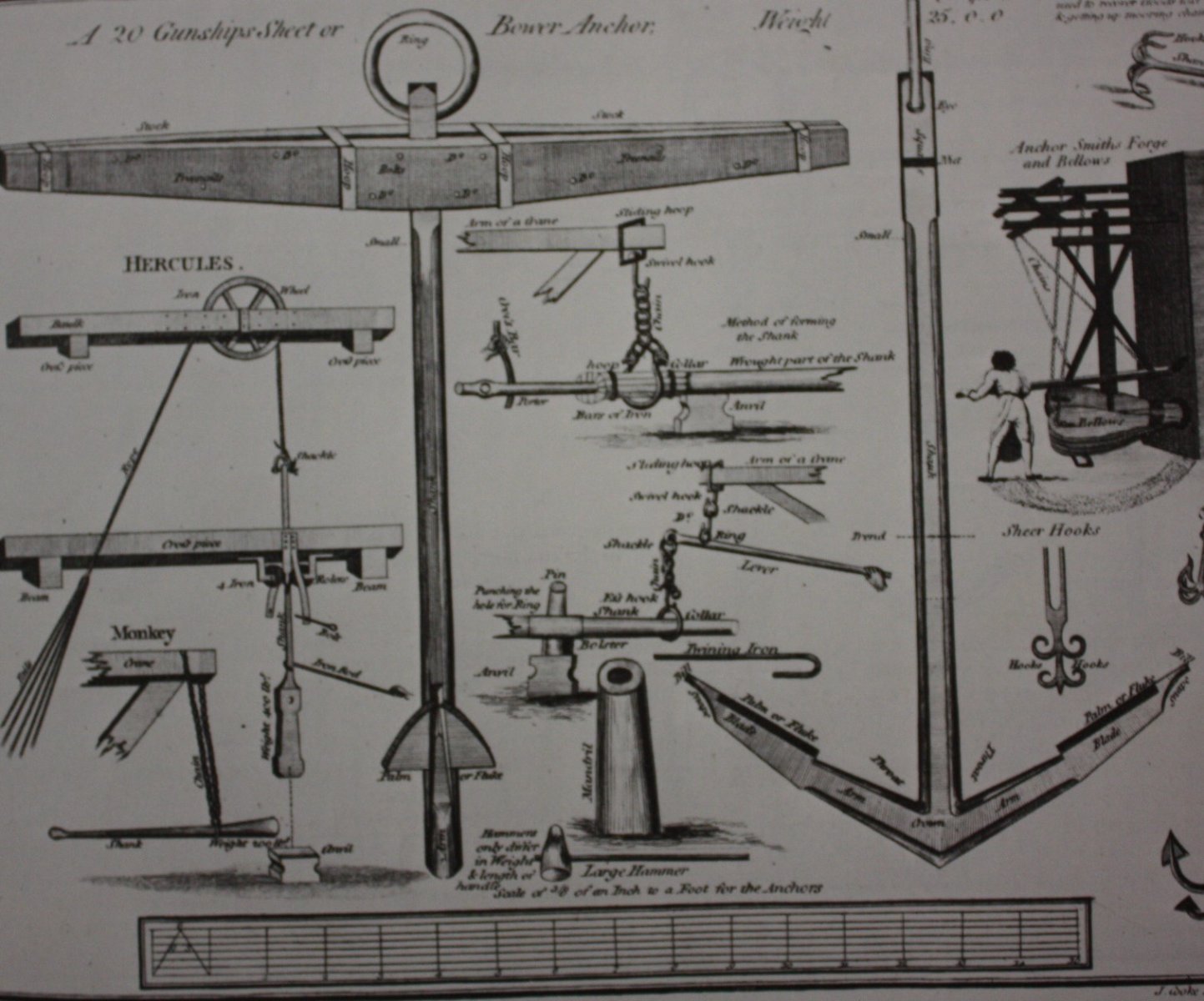
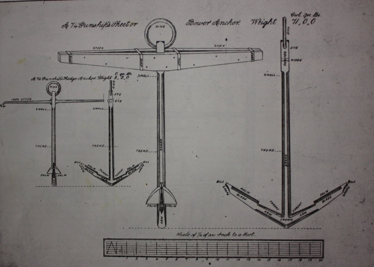
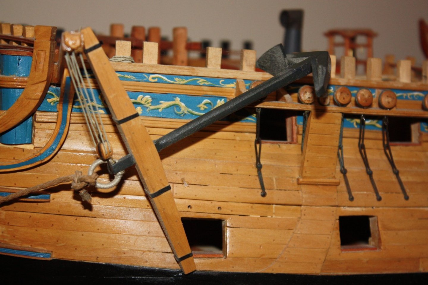
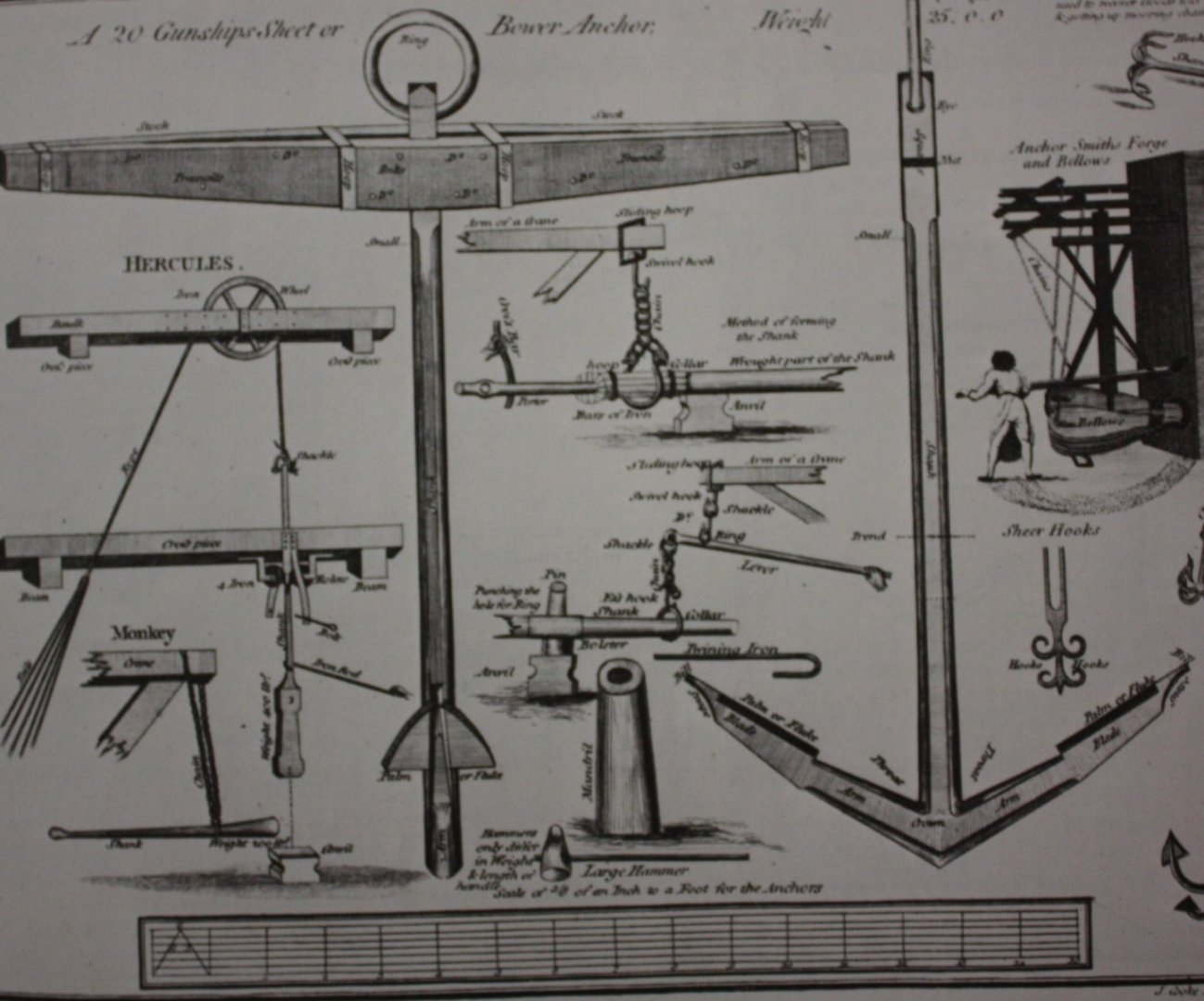
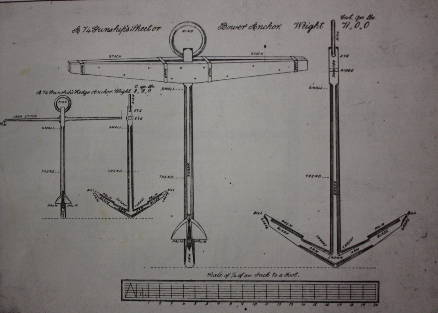
Scotty, no reflection on you at all, but these anchors do not look right. Not only the ring, the bands around the stock as well. They look to be far too thick and the proportions overall look a bit off. The photo above in Richard's post shows a great looking anchor. These are easy to make with simple hand tools. Lacking ebony, wood painted black works very well as in the photo below. Contemporary anchor drawings are below as well. They are not necessarily for your ship, but may give you an idea on proportions. Allan
-
Plastic to wood. Epoxy...........after you clean the surfaces to their original condition. You will need to hold it tight together until the epoxy cures. Allan
-
How do I tell what size scale rope should be used?
allanyed replied to JoeMacD's topic in Masting, rigging and sails
Joe, There is a spread sheet prepared by the late Danny Vadas for British ships that will give you the sizes of masts, spars, standing and running rigging for every line in the Articles database here at MSW . It is based on the ratios in the James Lees' book The Masting and Rigging mentioned by Gregory in his post above. One exception, do NOT use it for the period 1670 through 1710 as the base formula Danny came up with for that period is completely wrong so all dimensions that result from your initial input will be incorrect. Other periods are identical to those in Lees' book. Go to https://thenrg.org/resource/articles and scroll down to rigging articles. Allan -
I am pretty sure the forward most guns are aft of the forecastle, not under it on the Blanford. Apologies for the pasted mess below but it is to scale, and from the Blanford AOTS book by Peter Goodwin. Allan
-
margin plank/waterway
allanyed replied to DaveBaxt's topic in Building, Framing, Planking and plating a ships hull and deck
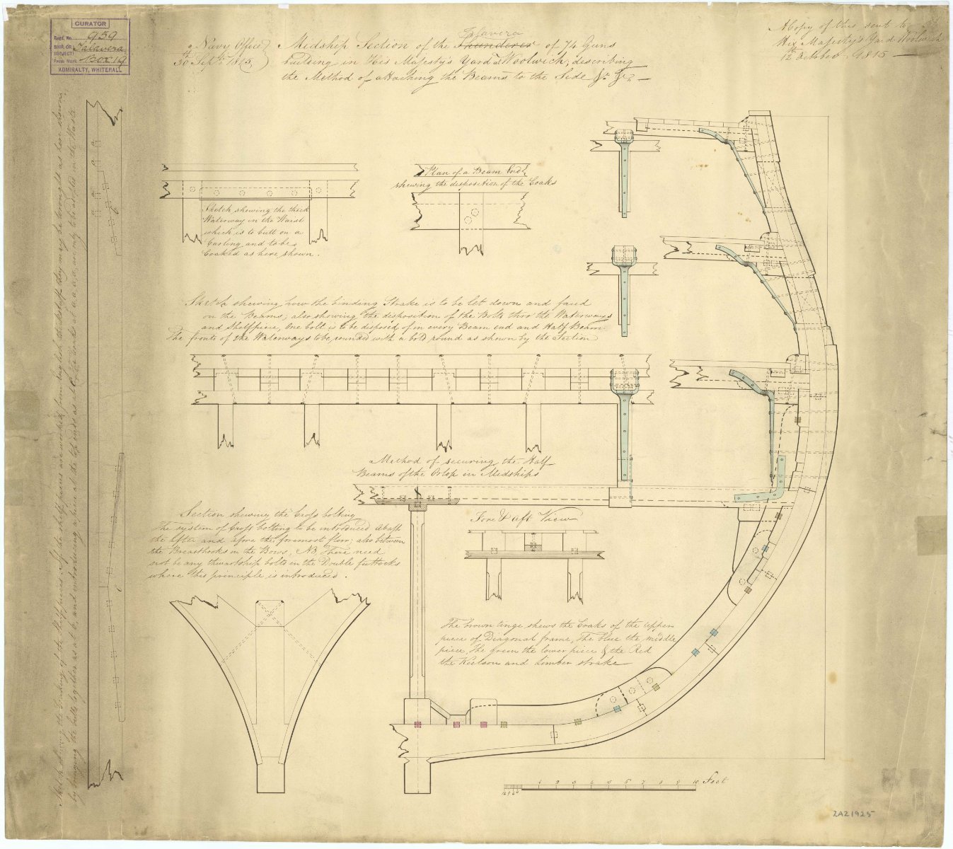
Hi David, There are scuppers for the water to run out. The waterways on each deck vary. From The Elements and Practice of Naval Architecture by David Steel the water ways on the FC of a 38 gun ship is 4" thick and the adjacent plank is 3" oak while the flat of the deck is 3" Prussian Deal. The dimensions from the Shipbuilder's Repository 1788 are the same for the forecastle. By comparison, the upper deck waterway is 5" thick and 11" wide per Steel, (4.5" thick per Shipbuilder's Repository 1788) while the flat of the deck, including the margin is 3" thick. Steel states that there are four strakes of English oak next to the waterways on a 38, then the balance is Dantzick deal. Each deck is addressed in The Elements and Practice of Naval Architecture as well as the Shipbuilder's Repository 1788. While the below are some years later than the Artois class 38s, a couple cross section drawings from RMG are below that might also be of some help. Hope this little bit of info helps David Allan_CROSSSECTIONWITHPLANKINGDETAILSRMG_J4486.png.645b66b0d53728fc05271ef83036c652.png)
-
margin plank/waterway
allanyed replied to DaveBaxt's topic in Building, Framing, Planking and plating a ships hull and deck
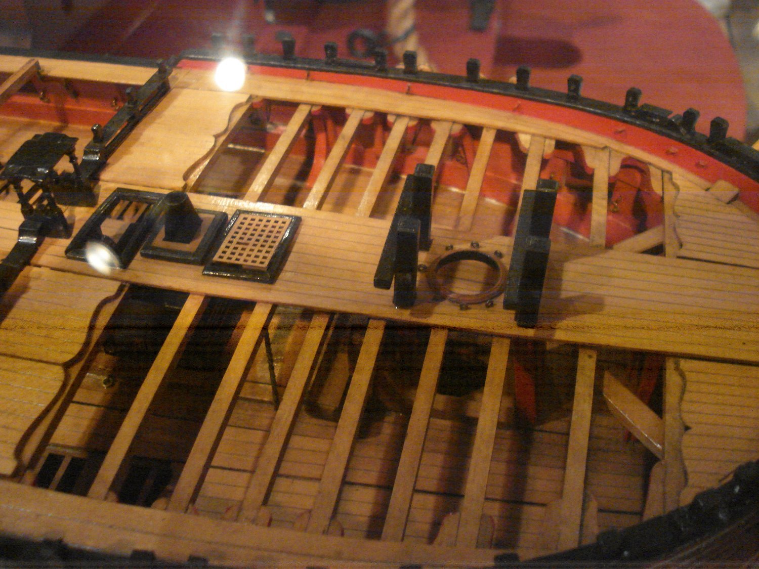
Hi Gary You may be correct but Peter Goodwin, author and former keeper and curator of HMS Victory shows in The Construction and Fitting book on page 60 that the margin plank was joggled if the length of the tapered edge was more than twice the width of the plank. He includes a drawing of same on page 58. He does not quote a source so I have no idea if he is basing this on contemporary information and/or this era. By the same token the below contemporary model of Minerva at Preble Hall shows how the planks were shaped at the ends without cutting into the margin plank. As you say, in this case they butt up against the margin, but they are still interlaced with each other rather than the margin plank, not with a straight tapered edge that comes to a point. This convention is shown on page 172 of TFFM, Volume II as well. Allan
-
Beautifully executed model. I have posted this elsewhere, but if you or your build log followers had not seen it, does anyone know where I can find contemporary drawings (not kit designs) that are dimensioned or drawn to scale, of Spanish naval ordnance from the 17th and 18th centuries? Thanks Allan
-
Source for 1/16th x1/64 brass strip?
allanyed replied to glbarlow's topic in Metal Work, Soldering and Metal Fittings
Seems right Roger. I got curious and did some digging and found this. At best, humans can resolve two lines about 0.01 degrees apart which is a 0.026mm gap when 15cm away. In practice, objects 0.04mm (0.0015") wide (the width of a fine human hair) are just distinguishable by good eyes, objects 0.02mm wide are not. Allan -
This is a long reach and I am sure is totally wrong, but lacking anything better ...... A gracchiatore translates to croaker. A croaker is a kind of fish. Maybe it is named after the type of fish???? Yeah, I know, I know,,,, I can hear the groaning, but that's the best I can come up with. Allan
-
Tony, Well there goes 20 minutes I will never get back. I could not find anything.🤪 If really important, you might want to try contacting the maritime museum in Paris. https://www.musee-marine.fr/paris
-
You might want to try Harbor Models in Glendale https://www.harbormodels.com/kr63040.html Allan
-
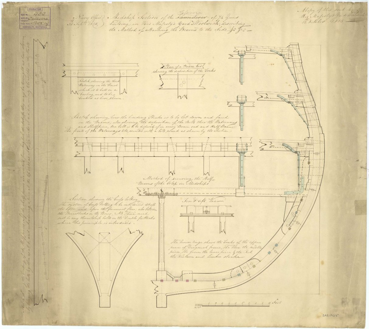
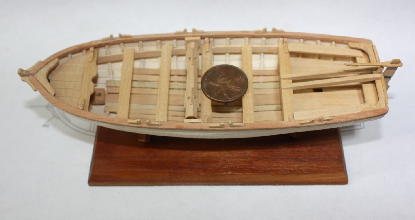
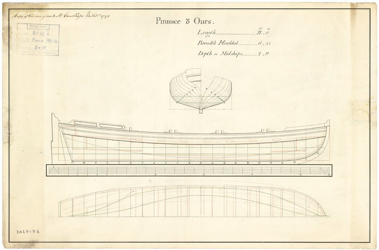
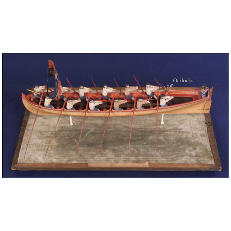
B&L Your workmanship on the boat is very nicely done! FOR THE FUTURE - I realize you duplicated the build on the site you show above. Unfortunately it looks like it is either set up for a double banked boat but missing rowlocks for four thwarts, or, if it is supposed to be single banked there should be one rowlock on alternating sides for every thwart. This is a common mistake as contemporary drawings' side views usually only show one side of the oarlocks so many presume it is the same on both port and starboard which is not the case for single banked boats. Drawing below showing 7 thwarts and 4 oarlocks. The photos below show single banked boats. FYI boats that were double banked were normally at least 7'6" in breadth. While Syren was a US ship, there would likely be similarities if not duplication of British design in this time period. Allan
-
Source for 1/16th x1/64 brass strip?
allanyed replied to glbarlow's topic in Metal Work, Soldering and Metal Fittings
3/4" should be close or perhaps a little bit too thin. The 1719 Establishment gives them 3/4" for a 40. There were no 32's in the 1719 Establishment so the 3/4" may be the closest to a 32 without under sizing. The 1745 and 1750 Establishments do not indicate a size, but the trend was to go thicker as time went on . In David Steel's The Elements and Practice of Naval Architecture he gives them at from 1" to 1.25" thick depending on the size of the ship/port lid. Goodwin shows an example at 1.5" thick on page 188 of the Construction and Fitting. Keep in mind the thickness often reduced from the area of the shoulder to the lower area of the hinge. Allan -
Source for 1/16th x1/64 brass strip?
allanyed replied to glbarlow's topic in Metal Work, Soldering and Metal Fittings
Hi Glenn, I looked at McMaster Carr and they have nothing that narrow either. Maybe get 1/4 wide and cut strips with metal sheers. The strip will curl as you cut, but easy to flatten for filing and otherwise shaping. Allan -
Occre Santisima Trinidad - Mast/Spar sizing questions
allanyed replied to bc_63's topic in Masting, rigging and sails
Hi Bryan While they are British ships, there are drawings of spars and masts on the RMG Collections site as well as on the Wiki Commons site. One example https://www.rmg.co.uk/collections/objects/rmgc-object-86593 There are also detailed drawings and text on pages 2-7 in James Lees book The Masting and Rigging of English Ships of War 1625-1860. Too many to post here as it is copyrighted material. Allan -
Just tuned into your build and happy I did. Absolutely lovely work Allan
-
HMS Euryalus 1803 by rlb - 1:48 scale
allanyed replied to rlb's topic in - Build logs for subjects built 1801 - 1850
I totally agree. Too often many of us forget that simple tools are often the best way to go. I love my mill, but I have been using chisels for far longer and plan to continue to use them. Allan- 122 replies
-
- 4
-
-
- Euryalus
- Plank-on-frame
- (and 4 more)
-
If you are still undecided, do you have any kind of CAD program, including Paint which a free app with Windows? You can make the frieze work then save and print on paper. You can make it in a large scale so it is not hard on the eyes while making it, then reduce and print so the size is appropriate to your scale. Considering the age of sail, if you are going to show her as she actually looked in 1796, it would then be appropriate to remove the name on the stern as the Admiralty did not allow the names on the RN ships before 1780 or after 1790. Allan
- 61 replies
-
- 1
-
-
- Agamemnon
- Ardent-class
- (and 2 more)
-
Your cutter looks super and it such a great thing to see the research you put into it before starting to build it. Allan
- 310 replies
-
- 2
-
-
- Diana
- Caldercraft
- (and 1 more)
-
Your planking is exemplary. It is a pleasure to see planking done as was done in actual practice rather than the fantasy planking seen so often. Regarding the wales, they were commonly black, so yours being darker is probably a good thing. Allan
-
Hi Bob Yes, but in what country do you reside? There are good suppliers in a number of countries. Which Endurance? There have been at least 3 including Endurance 1912. You can make a mold in silicone rubber of one or more of the 13 that you have, then make them out of casting resin. Cheers Allan
-
Ey Looks like that is your first post, so welcome to MSW!! Allan
-
Post 3 above is probably the best advice I can think of. Add to that, the type of line you use. At your scale, you will probably be limited to very few circumferences but that may be a plus in the end. Regardless, if you can find the sizes you need in rope rather than thread go for it. For English ships regarding the cannon, contemporary models sometimes left off all the cannon and when they did have them they were rarely fully rigged (just the breech is often seen). I know most of us like to show the cannon, me included, so if you are making them fully rigged keep in mind for less than 32 pounders they used two single blocks, not a single and a double, which seems to be prevalent in modern day models. This includes both the running out tackles and the train tackle. Allan
- 19 replies
-
- 1
-
-
- running rigging
- standing rigging
- (and 1 more)