


allanyed
-
Posts
8,149 -
Joined
-
Last visited
Content Type
Profiles
Forums
Gallery
Events
Everything posted by allanyed
-
 Very neat work Nearshore, Am I correct that this kit has a double planked hull? The reason I ask is that I am wondering how you are going to get the nails out without damaging the planking if it is single planked. Thanks Allan
 -
Correct Glue
allanyed replied to Blacklab's topic in Painting, finishing and weathering products and techniques
I think there are a lot of members that fit this category. Blacktab, The main thing is to be sure there is no glue visible to begin with. Wipe up any excess that may squeeze out with a sliver of scrap wood and a wet paper towel and if you use CA anywhere, use acetone in lieu of water. This will minimize scraping and sanding dried glue which, if not removed, will show big time when the wood is stained or coated with a varnish, oil, or poly finish, etc. Allan -
What a great photo in your post!!! Welcome aboard Allan
-
Lofting article
allanyed replied to a topic in Building, Framing, Planking and plating a ships hull and deck
Hi Guy I am not sure if this will help but take a look in the Articles data base here at MSW in the Plans and Research section and see Wayne Kempson's treatise. While it's set up for CAD, it may still be useful for hand drafting in many respects. Allan -
J Class Yacht Rigging Question
allanyed replied to David Lester's topic in Masting, rigging and sails
Phil I have no love for working with any kind of wire, but that has been my experience so maybe time for another try using the wire you mention. Are you using crimps or some other securing method and do you find it difficult to keep things tight? Pictures???? Thank you very much. Allan -
Gluing the axle ends is an interesting variation. Whatever works !!! 😀 Allan
-
Well done! With your skill set, you would do well with scratch building, making the world your oyster when it comes to selecting a model that has not been done thousands of times before. Allan
-
J Class Yacht Rigging Question
allanyed replied to David Lester's topic in Masting, rigging and sails
I look forward to following your build log David. I totally agree that using wire is a nightmare. I had more pin holes in my fingers in one session than all the tiny cuts from scalpels over 40+ years. I have a couple spools of the stuff in the shop that will take care of hanging pictures for the rest of my life. Do try getting some metal like thread instead of the wire. Would the wire color be more towards black than grey? It easy to make crimps regardless of the color to avoid serving but I am not so sure seizings and serving was not used on racing yachts 100 years ago, Roger you probably have it right, but was this the norm when Shamrock V was in her racing heyday? I suspect some research should turn up some contemporary photos that will give the answer. Allan -
Turn a scalpel blade into a saw
allanyed replied to bruce d's topic in Modeling tools and Workshop Equipment
Great video Bruce! Just before the making of the saw he explains about using bees wax for tempering and hardening his home made stabbing and carving tools which was a new one for me. The saw blade making looks like a great idea to try! Thanks for posting the video, it is very much appreciated. Allan -
J Class Yacht Rigging Question
allanyed replied to David Lester's topic in Masting, rigging and sails
I know it is a 7 hour drive from Cobourg to midtown Manhattan, but if you can do it, contact the office of the chairman of the Model Committee at the New York Yacht Club to arrange a visit. I think the current chairman is Peter Sweetser. In years past they left me alone for a few hours with the collection to make sketches (but no photos at the time.) Perhaps now they will also allow photos. It is a fascinating collection of over 1200 of some of the best schooner and racing models in the world. Allan -
Hi Craig The last photo shows it very clearly. This is exactly how I was taught as well. VERY well done! Allan
-
Turn a scalpel blade into a saw
allanyed replied to bruce d's topic in Modeling tools and Workshop Equipment
Thanks Bruce! Can you share the link to the video? -
Hi Craig, It is hard to tell from the photos, but will the overlap yield the clinker built planking found on cutters along their entire length (except where there is gain near the bow to eliminate the lap straking at that area)? With the bevel you make, it seems it will mate the edges to look more like carvel built then clinker built. Many thanks Allan
-
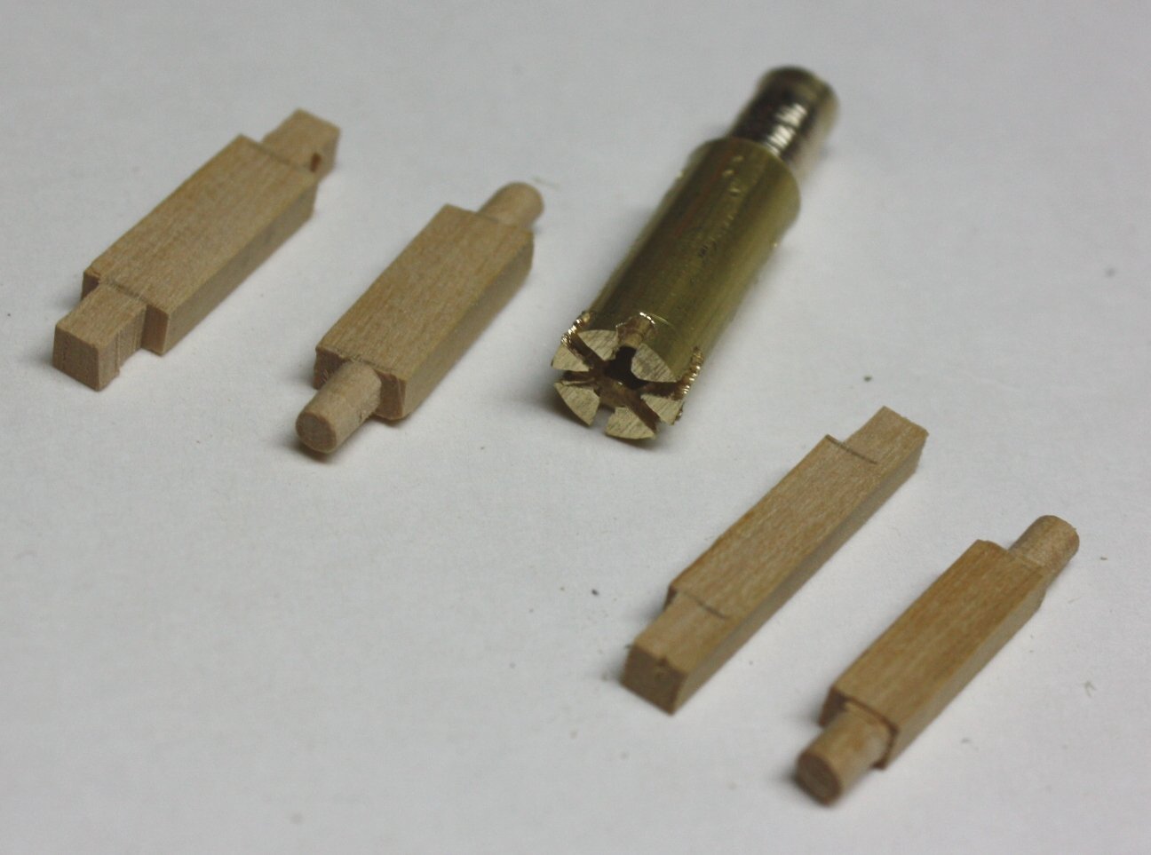
She looks great! I love that you rounded the axles for the trucks. Did you round by hand or use an axle cutter like the one I made with a drill and hacksaw below? Thanks Allan
-
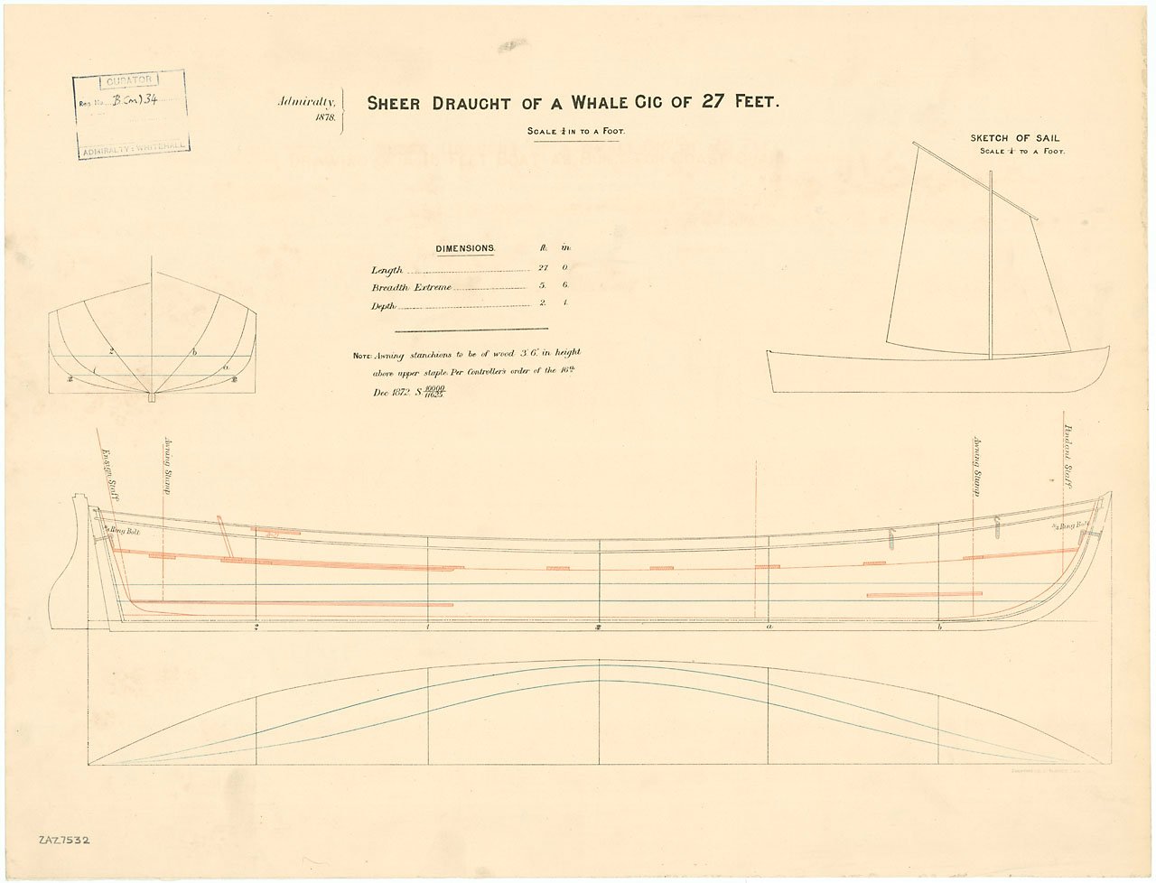
Do you know what kind of boats were on board, gig, cutter, launch, etc? Same for sizes of each of the boats. There are a number of drawings of ship's boats on the RMG Collections site as well as the Wiki Commons site, but it makes the search easier if you could search by type of boat. I have no idea if the example below is appropriate but it is from the Wiki site and will give you an idea of what can be found. Some of the plans are more detailed than others but most would be useful in building a model from the drawing. Sone are in high res, others in low resolution. Drawings on line at the RMG site are all low resolution, but can be purchased in high res if you find what you are looking for. Scantlings from W. E. Mays' book on ships' boats might also be useful even though the book is centered on warship boats. Everything from futtock dimensions to thwart widths and thicknesses are listed in those scantlings. Again, they are for ships of war boats and from circa 1800 but still may be useful to you. Allan
-
Craig, I just watched the video again, thanks for the reminder! Regarding the shape of the garboard, I tend to make it straight as you show with dotted lines, then use tick strips to mark out the balance of the planking widths. Also, I have been experimenting with tapering the planks as needed per the tick marks, then soaking for a while then fitting to the hull with clamps while wet and hitting with a heat gun. I let it sit for another few hours to completely dry so it has taken on and retains the proper shape and to be sure it has shrunk back to its original breadth before gluing in place. This makes it very easy to fit in place and finger hold for a few minutes while the PCA cures without use of clamps except at the stem and sternpost. I did notice that they are spiling in the video versus edge bending which of course is necessary with full size lumber. Also, they have included the ears which kit models always seem to forget as far as I have seen. Mays gives the dimensions for the ears of various types and sizes of boats in his list scantlings list of circa 1800. Regarding the planking thickness, it is to be just under 0.02" at 1:48 but I am going with just under 0.03" so I have some material to sand without sanding all the way through. Tricky but doable. Allan
-
I really am enjoying your log and I do feel your pain Craig. I am working on a 23 foot launch (drawing ZAZ7361 at RMG) at 1:48. The futtock dimensions are about the same as those you mention above as they are called out on the drawing as 1 7/8" at the heads (so about 1mmX1mm) with the floors sided 2" and moulded 3.75" at the throat. I like to use holly as it bends very nicely when soaked for 10 minutes with the plug method detailed in Frolich's The Art of Ship Modeling pages 170-174. Allan
-
Thank you for your update. Your log is a joy to follow! Allan
-
Welcome to MSW Maxx, Your project looks to be very interesting and a big challenge! Allan
-
Your model is looking fantastic!! This has to be the best beginner kit available along with the other two in the series. Your weights are very cool. Beats using scrap pieces of steel blocks as I have been doing lo these many years. Allan
-
Roger, Do you use this on synthetics, cotton, linen, or all three? Thanks Ulises, Same question to you regarding the Master Flat Clear Varnish Thank you Allan
-
What you say makes a lot of sense Mark, but this model as well as a few contemporary models I was able to find show stops/linings, rather than bucklers. I suppose it is another mystery amongst hundreds more that continue to pop up in our research in this great hobby of ours. Makes for a far more interesting hobby than if everything was straight forward.😀 Allan
- 113 replies
-
- 1
-

-
- Cheerful
- Syren Ship Model Company
- (and 1 more)
-
Daniel, At such small scales, your method sounds great, thanks for sharing. I have been unable to find any information on the circumference of the reef points other that they are braided (not a good idea at our scales) but they had a length that is twice the circumference of the appropriate yard, and two per cloth, (thus about 12 inches apart.) (David Lees' Masting and Rigging page 74) Allan
-
How many ships rattle?
allanyed replied to harlequin's topic in Building, Framing, Planking and plating a ships hull and deck
Enough scrap wood to make a ship's boat if I ever got all the stuff out of the models😀 This was discussed during the Wellington Trust Webinar that was announced here at MSW early this year and there were some interesting finds with the use of the endoscope. Allan -
Hi Glenn, I am not questioning the presence of port lids as their presence would be very unusual, but rather why are there port lid stops when there are no lids to seat against them. Can't get my head around this🤪 Allan
- 113 replies
-
- 2
-
-
- Cheerful
- Syren Ship Model Company
- (and 1 more)