allanyed
-
Posts
8,137 -
Joined
-
Last visited
Content Type
Profiles
Forums
Gallery
Events
Everything posted by allanyed
-
 Sorry Druxy, but I am not sure what you mean. The following is a cross section showing the keelson and bottom boards that I drew (post #1) Along these lines (forgive the pun) Mays gives scantlings for footwaling. Is this the same thing as the bottom boards? A larger pic of my cross section follows: Thanks!! Allan
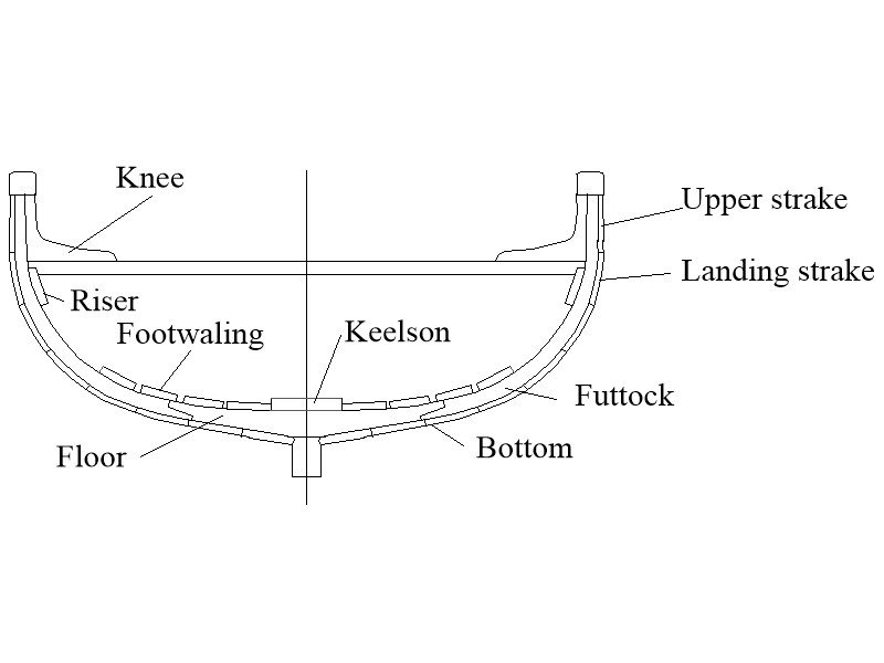
-
All things considered, what you have achieved so far is very impressive!! Will you be planking the second later the same as the first layer? The tutorial on planking here in the Articles section and the Chuck Passaro video on planking are a tremendous help for anyone wanting realistic planking on their model rather than what some kits propose. When it comes time to build the launch that Bligh used (he did not use the jolly boat, it was rotted through) consider taking a look at the build log on making this launch yourself. https://modelshipworld.com/topic/33539-23-foot-launch-by-allanyed-bounty-late-18th-century/ I look forward to your next post Allan
-
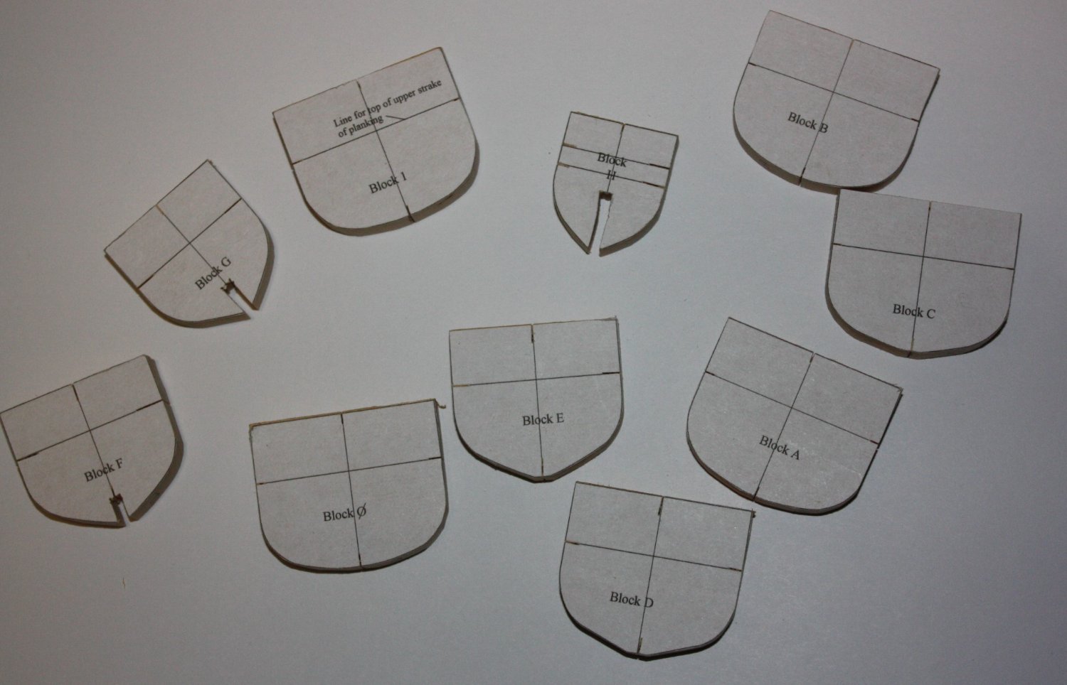
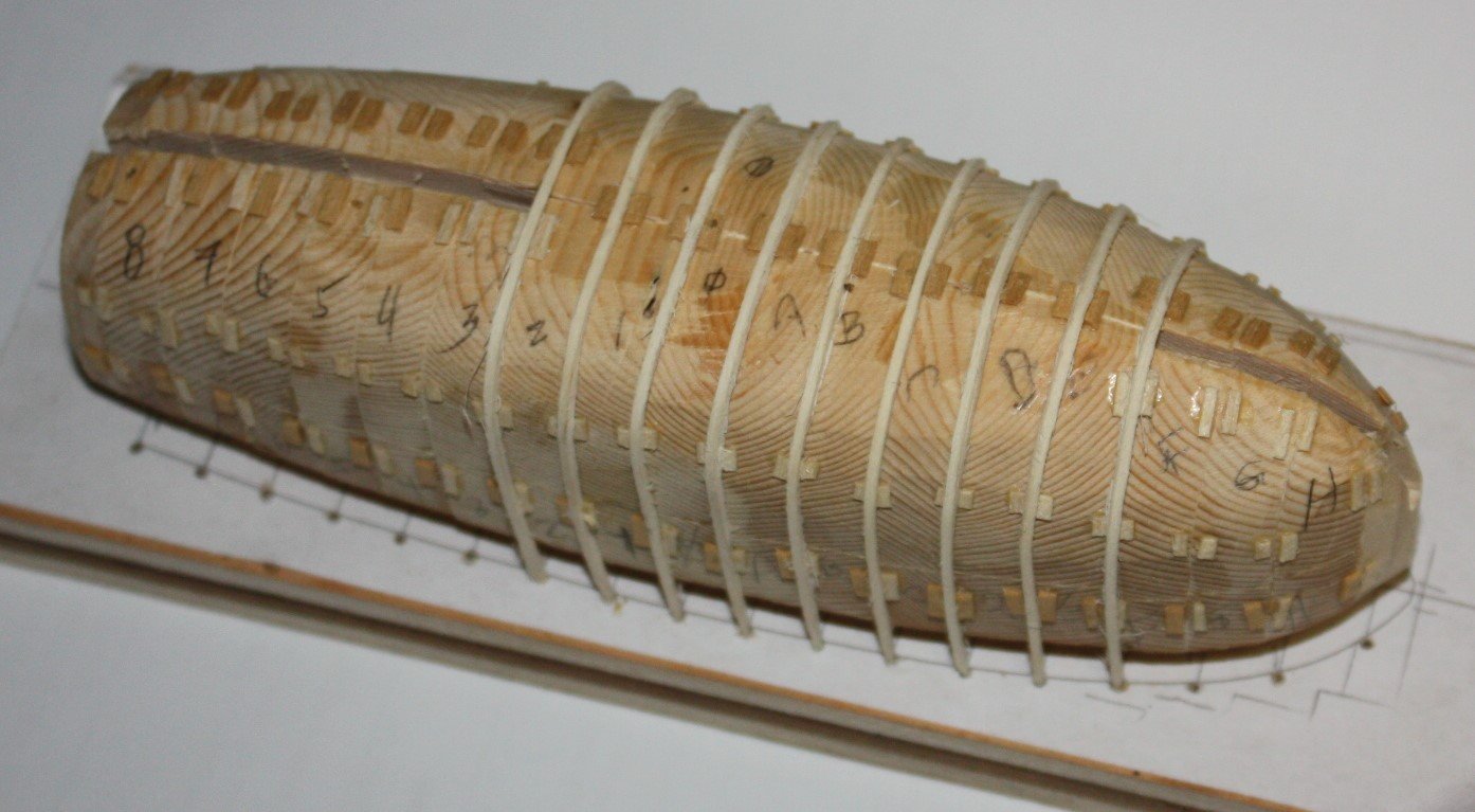
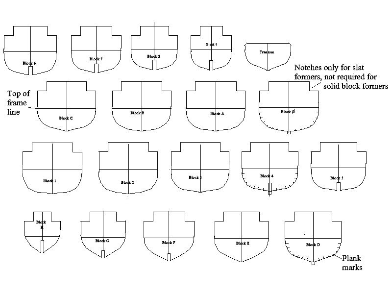
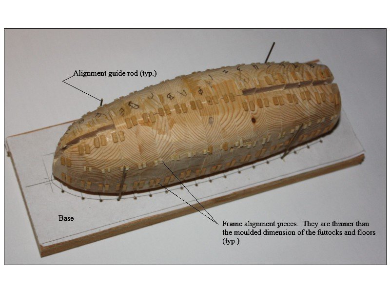
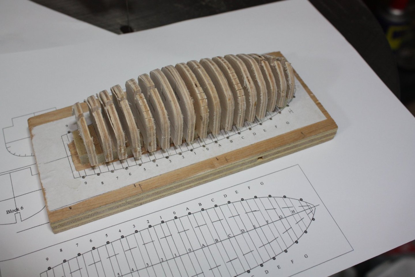
Frames in place on both types of forming blocks follows. The frames are made of holly which bend like paper when soaked in water for 10 minutes at smale scales. A few of the full frames did crack while being bent over the form, but extra material had been sized so not a big problem to replace these. I had experimented with other woods and poplar works nearly as well if thorougly wetted for a half hour or so. The guides on the solid plug MUST be thinner than the frames to avoid having the hull glued to them when gluing on the planks. The drawing of the individual formers follows and available for anyone that wants it in whatever scale they prefer if downloading from here does not work out so well. I use a spacer block under the plug, but cut indents for the slat formers which are glued directly to the building board. The top of the frames is marked on each section. Several have been marked with the plank line. There are 8 strakes of planking to bring the width to the scantling figure of 7.5" at station 0. These and the balance of pieces can be marked later as would be done on the ship model itself with tick strips to get the proper taper of the planks. Full frames set in place. NB: I found that the planked hull came free of the slat style former more easily compared to the solid plug. Removing from the solid plug took some jiggling and a few scary moments. The moulded dimension of the frames is more than the futtocks which taper down to 1.5" square at the head of the futtocks. Shaping these is a bit of a chore but not difficult. In practical terms, with the keel, planking, keelson and footwaling covering the floors, the frame material can be 1.5"X1.5" the entire length and the floor moulded dimension will not really be noticeable. Builder's choice.
-
Love it Craig. I debated with myself on the construction of the frames. The floors being separate from the futtocks as you show is more realistic, but I settled for something easier for most builders with a minimum of tools and smaller scales. If I were doing this in 1:36 or 1:24 I would cut out the floors and frames as you show and as seen in Frolich et al. Allan
-
Lyle, The model is looking really nice! I realize the launch on your ship is a kit conception, and not to steal your log, but for the future, if you or anyone is interested in this little vessel from the Bounty a lot has been discussed here lately at MSW in the Plans forum and maybe check out the following build log if you wish. modelshipworld.com/topic/33539-23-foot-launch-bounty-late-18th-century. Allan
-
Your photo needed more than a simple "like". Great pic!! Allan
-
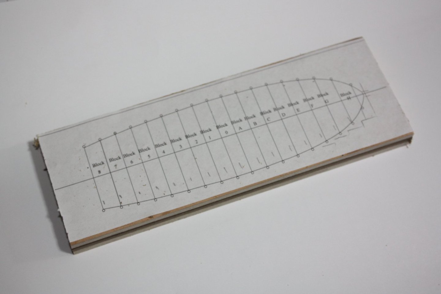
Craig, After double checking I made the edits on the scantlings and drawing. Keep 'em coming, I really appreciate the help. Regarding the davit, my original design was based on the follow, ZAZ7145, the yawl as you pointed out. I am still not sure which is more appropriate but as ZAZ 7355 is a launch, I am going with that design as shown below. Anyone building a yawl might be better served using the AZ7145 design. There were a lot of questions that arose as this project moved along including the spacing of the frames. I used the station lines from drawing for the location of the frames. Note that there are far more frames than usually seen in ship's boat models. The first style of forming plug that I have used is based on what I originally found in Frolich's The Art of Ship Modeling. The thickness of the plug pieces is the same as the room and space. NB: The plug designs were drawn so as to be the inside of the frames not to the station lines on the body plan which are the outside of the frames. Alternate forming plug, using 1/8" plywood, which is easy to find and does not require thicknessing the plugs.

-
I can attest to this situation being hair raising. Happened to us when we were out in our boat fishing for striped bass one Spring morning between Sandy Hook and the Verrazano Narrows Bridge. We were out of the shipping lane that comes down the Raritan Reach so we just sat ---- untl we heard thunder. We pulled anchor to run for shore. Which way??? The compass showed us our heading. (Of course the GPS made it even easier😁) Still a scary situation.
-
Good catch, thanks!! What you show is how I have done this in the past but then I saw this version elsewhere. Time for some isopropyl to remove and redo. It will all be covered, but may as well get it as close as we think it would be. Thank you for your input, it is very much appreciated. Allan Scantlings.pdf
-
David, You would only be dumb if you have a question and fail to ask it. For me, it seems we too often forget to ask those questions or do even a modicum of research before plunging ahead. Ask away!!!! Allan
-
Greetings from North Carolina
allanyed replied to PostCaptainAubrey's topic in New member Introductions
Welcome aboard and good luck on your project. Allan -
Further to what Gregory posted, it is my understanding that the binnacle was not a permanent structure but rather was lashed down when in use and was put out of the way when not in use so not shown on contemorary plans. I also wonder if it was not stowed when preparing for battle to protect it from damage or, at times such as Gregory mentioned. Up to three binnacles, (or abitacli, or habitacles) were carried at times but by order of the Admiralty this was reduced to two in 1779 unless demanded by flag officers. In these cases it is not clear where these additional units were kept, possibly below as spares. If you study some contemporary plans you will usually see the capstans and wheel hub, but not the binnacle. I just took a quick look at about 50 profiles and inboard profiles and only saw one structure that might be a binnacle. Look at ZAZ3401 at the RMG Collections site, HMS Coventry 1757, et al. There is something just forward of the wheel that MAY be a binnacle. A high res plan can be seen at https://upload.wikimedia.org/wikipedia/commons/8/8b/Coventry_(1757)%2C_Lizard_(1757)%2CLiverpool_(1757)%2C_Maidstone_(1758)%2C_Acteon_(1757)%2C_Shannon_(1757)%2C_Levant_(1757)%2C_Cerberus_(1757)%2C_Griffin_(1757)%2C_Hussar_(1757)%2C_Bureas_(1757)%2C_Trent_(1757)_RMG_J6339.png Whatever this object is, it is not shown on the deck plans, so might be temporarily in place, thus the binnacle. Hope others have more information to share. Allan
-
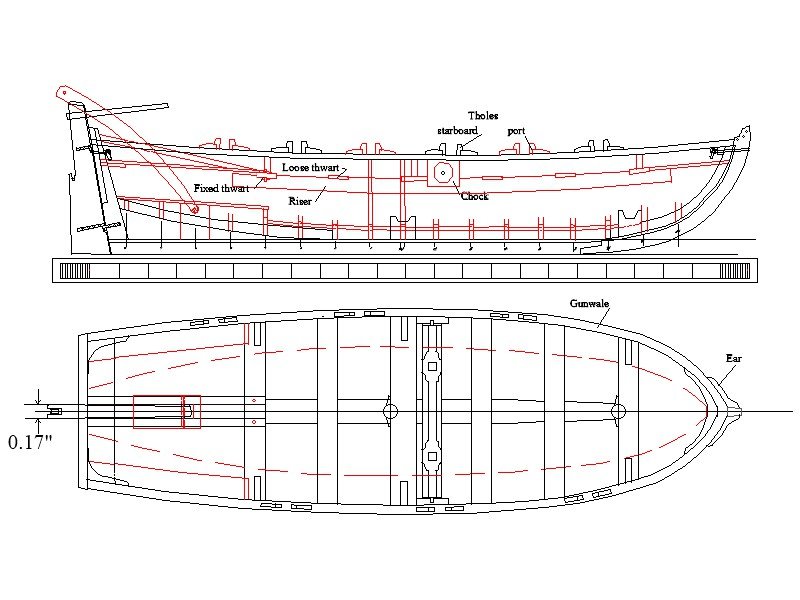
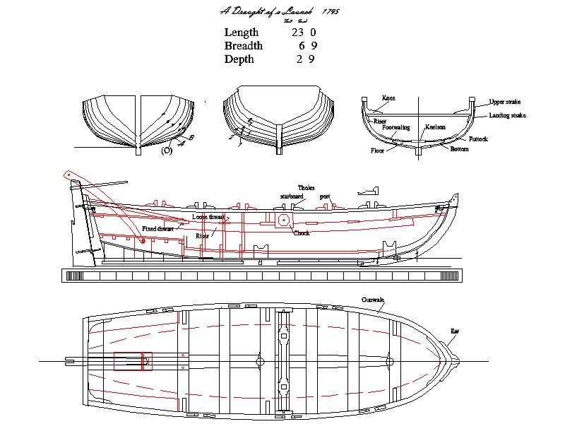
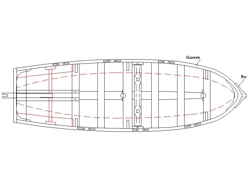
When considering models of the Bounty’s ship's boats there are quite a few on MSW alone. There are a number of things that have bothered me about these models so I wanted to see if I could do something different even at a small scale. If anyone has any solid contemporary information that specifically contradicts what I have used for this launch I would be very happy to build another version of this boat and correct any and all mistakes. The drawings were done at full scale 1ft.= 1 ft then reduced to 1:48. for this project. Many/most of the logs on various modeling sites are for the Bounty jolly boat that Lt. Bligh ostensibly used for his famous voyage. In reality there was never any kind of long voyage with Bligh in a jolly boat. The jolly boat on the Bounty was rotted and would sink if put in the water. The cutter was also leaky and too small so the boat that was used on the famous voyage was the 23 foot long launch, not the jolly boat nor the cutter. There are items regarding the launch at the time she was used by Bligh and his fellow passengers that have been questioned, but with the drawings from RMG, the scantlings found in W.E.May’s book The Boats of Men of War, and Bligh’s notes., I thought it would be worth a TRY to yield an accurate model. Is it perfect, heck no! I just wanted to use methods that I am pretty sure anyone can use to build the Bounty launch or most any ship’s boat. At the smaller scales perhaps some kit builders will find this build useful in providing an accurate ship’s boat for their Bounty or other ship. First up is the initial drawing. The below is based primarily on RMG drawing ZAZ 7361 with additions based on additional research. NB: If anyone wants a copy of any of the drawings that will be following please feel free to EMAIL me with their email address and what scale they want. My email is in my profile. I can send as tcw, pdf, jpg, pnb, dxf, tcw, bmp, or dwg format. I prefer to wait until the log is complete and corrections, if any are needed, are made. List of scantlings. Dimensions shown on the drawing ZAZ 7361 were the primary source of those shown below. Where dimensions could not be taken from the drawing, the list of scantlings found in W.E. May’s book, The Boats of Men of War were used. Length 23- 0” Breadth 6’ 9” Depth 2’ 9” Feet Inches Room & Space 1 2⅜ Stem, sided 3⅜ Keel, Square Midships 3¾ Post sided at the tuck 3⅜ below 2⅞ broad fore and aft at the keel 8¼ Transom thick 2½ sided 2 Floor timbers sided 2¼ moulded -at the heads 2⅛ -at the throat 3¾ Futtocks sided below 2 square at the heads 1⅞ Keelson thick 2 broad 9½ Footwaling thick 1 Bottom planking thick ⅞ broad 7¼ Landing strake broad 7¼ Upper strake broad 8 Gunwale deep 3 Thick 3¼ Washboard broad at the bow, if included 6 Rising thick 1 broad 5½ Thwarts fixed thick 2 broad 10 Thwarts loose thick 1½ broad 8 Knee on three fixed thwarts sided 3 Benches thick 1½ broad 11 Deadwood sided 3 Breasthook sided 3 length (each arm) 1 10 moulded at the throat 6 Windlass diameter 8 Chocks thick 3 broad 1 1½ up and down 11¼ Ears sided 6 length 1 3 Rudder breadth at the heel 1 4¾ breadth at the hance 1 0 breadth at the head 6¾ thickness 1 Rudder pintle thick ¼ and gudgeon width 1 quantity two More to come. Allan Scantlings.pdf
-
EURYALUS 1803 by Peter6172 - 1:48
allanyed replied to Peter6172's topic in - Build logs for subjects built 1801 - 1850
Thank you for mentioning the need to taper this. The failure to taper the knee of the head both vertically and fore and aft is one of those things that seems to be prevalent but so easy to fix. -
I am basing this on the drawings we have been using as they show only one mast. Maybe she was built to have two masts originally, but then these drawings are open to question and possibly not reliable in other respects. The logs etc. indicate two masts but the drawings supposedly included in the Bligh papers show only one. Very confusing, at least to me. There is a lot of misinformation, including the modern models at RMG. Another example is at https://historycollection.com/the-mutinous-voyage-of-william-bligh-and-the-bountys-launch/8/ He posts a plan showing one mast but then goes on to say in the very first sentence that the launch had two masts. Allan
-
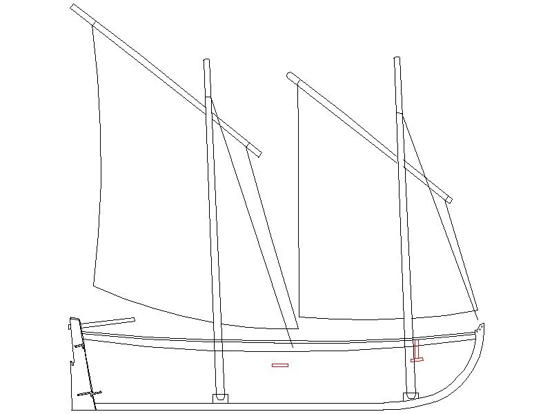
Hi Roger, No argument from me on that at all. That said, the lines such as stays and shrouds may still be valid. In addition I have played with the rig holding up the yard as alternative to the yard having a parrel and halyard reeving over a sheave within the mast. I have drawn both versions but not sure which was most likely used in this case. I am good with either choice unless if I can a find more definitive information. Lavery mentions that the shrouds were for stresses from both the sides and aft on page 227 of The Arming and Fitting of English Ships of War and "forestays braced the mast against pressures from forward on page 228." He makes no mention of backstays, so that question that I had seems to be answered. This may very well have been the case but as the launch was single masted when built, then modified during the Bounty voyage to the South Pacific, it has not been possible to find if the masts were farther apart or not. I show it about 6 inches aft of midships. The basis I used was a two masted cutter drawing ZAZ7022 of 1786. The aft mast is just about dead center along her length. Note that in this plan the forward mast is only about 10% of her overall length aft of the bow where as the launch original mast was 18% of the overall length aft of the bow. I have no idea if this played a factor in locating the aft mast. Also Lavery shows a photo on page 217 where the masts are separated by only two thwarts between the two that support the masts as I have shown. I realize this is a cutter in his photo, but the spacing principals may still apply. In any case the below is what I have come up with for now. Again, any definitive information to the contrary on any of the above is MOST welcome. Thanks for everyone's input, it is greatly appreciated. Allan
-
EURYALUS 1803 by Peter6172 - 1:48
allanyed replied to Peter6172's topic in - Build logs for subjects built 1801 - 1850
I totally agree with Giampiero, the build log from Matiz is awesome. For other templates, you can try to scan a part on a drawing then print it on label paper rather than using plain paper and glue. If you are missing any drawings or other information from the books with the transfer from Russell, feel free to PM Wayne or me. Allan -
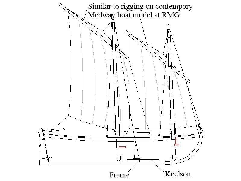
Craig, The only reference as to length is Bligh's request to replace the 20 foot launch with a 23 foot launch. The plans you and I have been referencing are for 23 foot launches and they do fit the time frame. Roger, I agree that back stays may not be needed, but stays leading forward?? There is so little contemporary information on boat rigging that guesses are not unusual for us. The only detailed contemporary model I can find that is rigged is the Medway long boat. RMG has modern models as well but I have my doubts as to their accuracy. I have yet to find a detailed contemporary rigging plan and would sure welcome one! Thanks guys. Allan
-
A little more detail has been added. Thoughts? The two indicated lines had me in a quandry until I studied the photos of the Medway boat model at RMG. I am still debating if there would be a single shroud for each mast on each side, or two as on the Medway model. Thanks!! Allan
-
Planking improvement
allanyed replied to Picard's topic in Building, Framing, Planking and plating a ships hull and deck
Did you bevel the frames before planking? If so, it looks like the plank above the one with the left red arrow is not seated completely against the bulkhead. I have found that soaking the plank thoroughly then clamping it to the frames without glue works well. Be sure the clamps have soft faces or put a piece of cardboard or soft wood between the wet plank and face of the clamp to prevent denting the plank. Then, heat it with a hot air gun for a minute or two. (Her hair dryer will work, but there are consequences if you get caught.) Once done you can remove the plank and it will hold the shape. Then you can glue it in place with finger pressure, no clamps. This will help assure the plank is seated well. Be sure it is completely dry as it will be expanded while wet, then shrink once dry. Alternatively, spile the planks. There is an excellent tutorial on here in the MSW articles data base by David Antscherl on how to do this. I find this a much better way to shape the planks for harder wood species. If your build is a kit, you will have to get sheet stock as you cannot use strip wood to spile a plank. Allan -
Exactly what I was contemplating Eberhard, Thanks again! Allan
-
LIke below? Thanks Eberhard Allan
-
Very neatly done planking Malcom. Also very inventive on the salt water corrosion!! Regarding the copper sheathing, unlike instructions in some kits, the plates should be installed so there are dents showing, not bumps as they were nailed to the hull, not riveted or bolted and they overlapped by 1.5 inches much like roof shingles. Just as an FYI for future builds, the actual plates were typically 15" X 48" and about 0.03 thick, thus 0.23"X0.75" and less than 1/1000th thick at your scale. A lot of modelers use copper tape as it is close to scale thickness and can be properly overlapped. AL has come out with a pinwheel punch to mark copper tape with nail dents. It is set up for 1/72 scale, so not to far off for 1/64. Looking forward to your future posts. Allan
-
Your build continues to be exceptional. One small thing that comes up on occasion, and I for one have not resolved in my own mind is the gun rigging. According to Adrian Caruana in volume II of The History of English Sea Ordnance 1715-1815 page 386, cannon on British vessels smaller than 32 pounders used two single blocks, not a single and double for the running out tackle. Same for the train tackle. I realize from the pics in your post #43, the drawing showd otherwise. Plate VII in the Universal Dictionary of the Marine, by William Falconer seems to show the upper deck guns with what looks like a single and double and these would be guns smaller than 32's being on the upper deck. Caruana shows a portion of this same plate on page 386 as well so it does not seem to be clear, at least to me. Is it likely that different blocks were used on different ships or was there a rule regarding the blocks? Hopefully a member can shed more light on this. Thanks for sharing your build with us. Allan
-
Sorry I cannot help in your quest, but please accept a warm welcome to MSW BG. Please post an intro about yourself in the new member section, it may generate more responses. Allan