


allanyed
-
Posts
8,149 -
Joined
-
Last visited
Content Type
Profiles
Forums
Gallery
Events
Everything posted by allanyed
-
 Your first layer of planking is better than a lot of models' second planking we see. Kudos!! It is almost a shame to cover it 😀
 -
Swivel guns
allanyed replied to tlevine's topic in Discussion for a Ship's Deck Furniture, Guns, boats and other Fittings
I have not been able to find a contemporary drawing that has a swivel gun mounted on a bulwark, so far. All I can find are stout posts on which they are mounted including the Fly drawing that Mark references in his post above. The drawing is available for free in high resolution on the Wiki Commons RMG site. upload.wikimedia.org/wikipedia/commons/8/84/FLY_1776_RMG_J7978.png I inserted and enlarged to full scale in CAD and measured from the top of the beams at the bulwarks to the top of the mounting posts. I don't have my books with me so do not know the thickness of the deck planks for the QD or FC. Going aft to forward, the tops of the posts at the QD run from 42" to 44". At the FC, they are 27" for the aft most and 29" for the forward most. Allan -
Yes, but that is not surprising considering the brand. If there are odd number of thwarts the boat is likely double banked as you rightly point out, and there should normally be the same number of oars working on each side of the boat. An exception at times were whalers in that some whale boats had two rowers on one side and three on the other. But there are also double banked with an even number of thwarts. The easiest way to tell is by the size of the boat. If the breadth is sufficiently wide, it is likely double banked. This brings up a good point for which I have yet to find an answer based on contemporary information. What is the minimum breadth for a double banked boat? The larger boats were double banked, but "larger" is a relative term and not at all determinative. Good for you!!! Allan
-
Finally, a Victory model that is both interesting and beautifully done. Allan
-
I had never really looked at how much wood goes into a model but after going back on my last orders of castello and what has come out of it, your figures look to be right on for full framing, planking and misc things. Breaking it down further, that is less than $50 for a fully framed model and even less for a POB. Add in holly and maybe pear or some such, the cost in materials is not as bad as many think it would be for materials that are far superior to those used by many, not all, kit makers. Allan
-
Thanks Harlequin. It is a hobby for the vast majority after all and should be an enjoyable pastime. Allan
-
Chimp, I am glad to help. That is soooooo true. Never a day goes by that I do not see and/or learn something new, especially here at MSW. Allan
-
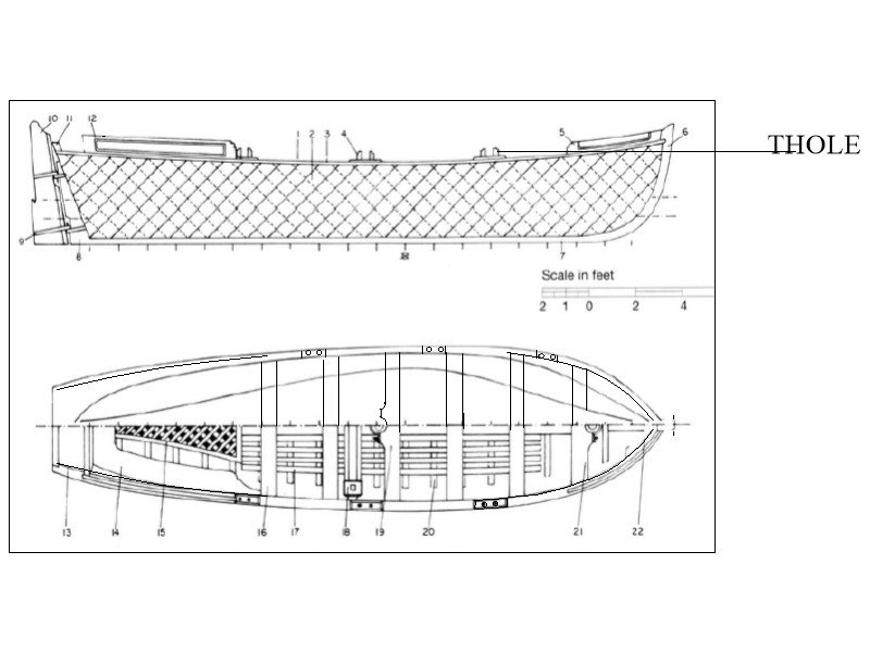
Hi Chimp The drawings you show appear to be correct unlike the OcCre boat designs which are OcCre's own fantasy. The drawings can be a little confusing. The top view only shows half the boat so it was probably assumed by many that the tholes were the same on port and starboard which is not the case for single banked boats. There are tholes on the alternate thwarts on the opposite side but are not always shown on the original drawings. There are photos of contemporary models of ships' boats on the RMG Collections website that show how the tholes were arranged. Lavery's Arming and Fitting and May's Boats of Men of War go into these kinds of details as well and are possibly two of the very best sources of information, including scantlings on everything from the ears to the futtocks. Allan
-
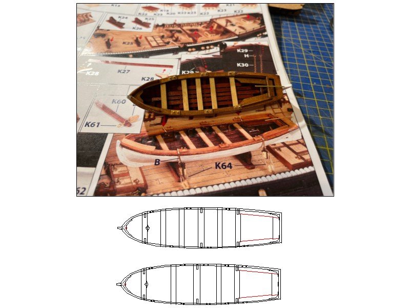
Penfold, Your workmanship continues to be very neat and solid, thank you for sharing with all of us. Just as an FYI, the tholes on ships boats did not look like the OcCre design nor were they located as shown. For double banked there would be a pair for every thwart and for single banked the tholes would alternate port/starboard for every other thwart. The photo in the plans shows neither. This is an easy fix even if OcCre got it wrong. The sketches below show single banked with six thwarts and double banked with five thwarts.
-
Neatly done work Harlequin! One question, hope you don't mind. Is the vertical planking on the transom a kit instruction? I had never seen this before so am curious how these planks are secured to the stern timbers as they are also vertical and rest on the wing transom as was standard practice. This can be seen on the contemporary drawing ZAZ6588 at the RMG Collections site. Thanks for continuing to share your build. Allan
-
Hello Glenn A very warm welcome to you! Good luck in your research and building. With well over 40,000 members, we have that many levels of experience and we are all continually learning new things so will not be alone in your quest. Allan
-
Super warm welcome to MSW Steve! Great to see another scratch builder in the fray. Love the model and the moustache is pretty cool as well!!!! Allan
-
This is an interesting point as well as the missing windlass. I thought it might be a matter of one pair being stern lights and the other pair gun ports similar to those I have spotted on other similar size sloops. Just as an FYI I found a drawing of a small single masted sloop, albeit early 19th century (1808), showing both a windlass and a capstan. Go figure..... https://www.rmg.co.uk/collections/objects/rmgc-object-85782
-
Frank Your build continues to be impressive to say the least. Perhaps the most impressive thing for me is that you took the advice from Gerard D and reworked all those lines/blocks. That was not a decision everyone would make and you are to be congratulated. Some members here would call you a rivet counter, but I for one see such action coming from someone that takes great pride in their work. Allan
- 510 replies
-
- 3
-

-
- reale de france
- corel
- (and 1 more)
-
I took a look at the plans as I have an interest in this vessel as well. I realize the lines drawings by Jeff Staudt are copied directly from ZAZ6368 from RMG and very accurate. I did notice that there is no windlass or other device forward as found on every other vessel of her type and size (or even smaller than Mediator) that I could find on the RMG Collections site. Does anyone know if this vessel had no windlass or is this an omission on the drawings for some reason? Would the crew actually have to manhandle the anchors via the cathead without mechanical help? I find it hard to believe there was no windlass or a small capstan, but surprises are not new in this hobby of ours. TIA Allan
-
Hi Kevin, Good for you in taking on this project! Looking at build logs here at MSW, with one or two exceptions, stock boats found in kits are ghastly, so your idea could be salvation for kit builders. For your clinker project will you be basing the scaled series for the hulls only? This makes sense as the number and scantlings for frames, thwarts, ears, and knees, and scantlings for deadwood, keel, planking, etc are not going to be scalable at the same ratios, if at all. Allan
-
Hi Kevin, If you are not locked into exactly that boat, Google surf boats and monomoys. While not exactly the same, especially at the stern post, they are similar in size and shape. What year is the boat in your drawing from? Allan
-
Good luck with that.
-
Thanks Bill, Looks like it could be a nice guide. The scantlings for spars, masts and size of rigging lines are easily found in the Vadas spread sheets here at MSW so you have some great sources of detailed information from which to work. Allan
-
Do you have his website address that you can post here? Thanks Allan
-
Hi Bill, From which kit maker does this plan come? Thanks Allan
-
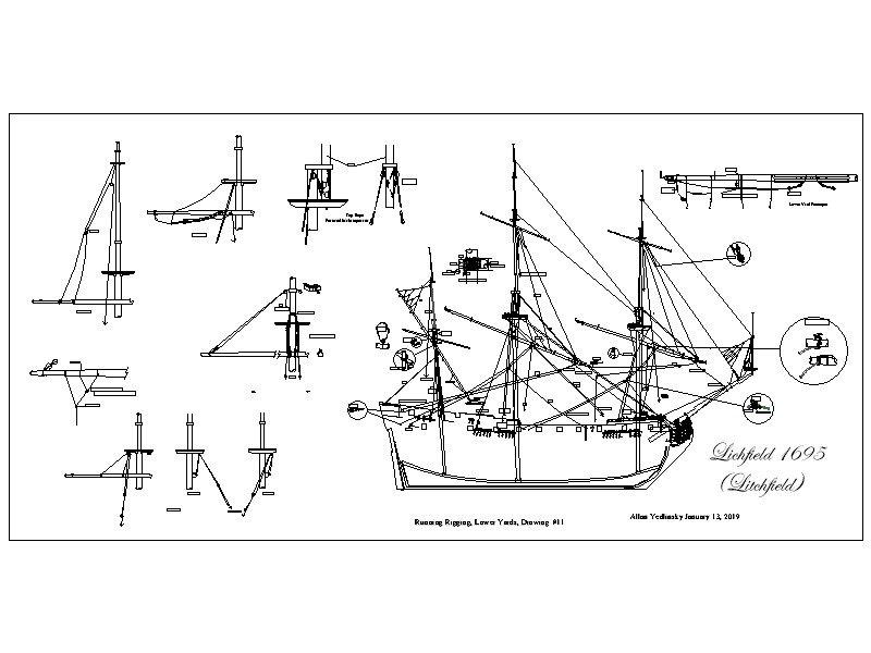
Good for you. Sails at this scale usually look like ugly door mats unless made of non-woven materials like silk span. As to rigging these lines without the sails, David Lees shows this in high detail in his book on rigging. I am traveling with no access to my books otherwise would transcribe his drawings and post for you. The below is for a late 17th century ship but it may give you a better idea of how the tacks, braces and sheets would be rigged with no sails. If you wish, PM me and I can email you a clearer copy of this drawing as well as for the upper yards. Allan
-
Deck planking plans
allanyed replied to KingDavid's topic in Building, Framing, Planking and plating a ships hull and deck
I can't find it either. BUTT, there is a lot of information various butt shifts in many ship modeling books. Are you looking to do a three butt shift or four? Allan -
Welcome aboard! Looks like you have selected all Caldecrraft kits which has a good reputation. But, as you are new to the hobby, you may want to consider starting with simpler vessels that will teach you great habits and techniques. There are numerous posts here at MSW with advice and opinions on which are good beginner choices. Allan
-
Congrats on a great build!!! Do you know if the carbon rod is epoxy reinforced carbon or plastic composite type or some other? Seeing your use of this material was new for me so I looked for it on-line and found there is more than one type, thus my question. Thank you Allan
