allanyed
-
Posts
8,149 -
Joined
-
Last visited
Content Type
Profiles
Forums
Gallery
Events
Everything posted by allanyed
-

Miniature Russian carving tools
allanyed replied to druxey's topic in Modeling tools and Workshop Equipment
Just PM'd you in case no one else has responded yet. Allan -
Peter, If the launch in the kit is not up to your liking, feel free to email me. My Email addy is in my profile. Allan
-
Gray, I TOTALLY agree with the comment from Gregory concerning pins. It is not necessary. Do read the tutorial on planking by David Antscherl in the Articles data base here at MSW and watch the Youtube videos by Chuck Passaro. These will enable you to do a proper planking job. If done well there is no need for pins or clamps. If you do need clamps for the planks that are not quite right the method John mentions sounds like it has possibilities. Be careful though that you do not dent the planks with the clamps. Study some planking expansion drawings as well. You will see how the planks narrow going forward and widen astern. There are several high res planking expansion drawings on the Wiki Commons web site as low res plans on the RMG Collections site. One example of a low res from RMG is https://www.rmg.co.uk/collections/objects/rmgc-object-83495 Allan
-
MIght it be easier to buy a small sheet of birchwood ply, trace the errant bulkhead onto the sheet and saw out a new bulkhead with a scroll saw or even a hand coping saw? Allan
-
Many thanks for the lead on the paper. You are absolutely correct about other black paper. Construction paper works very well, but can delaminate if not properly sealed with a clear coat. Now, to find a local source. Allan
- 310 replies
-
- 3
-

-
- Diana
- Caldercraft
- (and 1 more)
-
First and foremost, your model looks fabulous. The material quoted above that you mention is a new one for me. What is cartridge paper? It is very nice to see that you are researching so much such as foregoing the eyes and pre-rigging the blocks with toggles. Allan
- 310 replies
-
- 2
-
-
- Diana
- Caldercraft
- (and 1 more)
-
Rigging the Charles W. Morgan
allanyed replied to Tom Hairston's topic in Masting, rigging and sails
Call Mystic as Roger suggests and ask for Akeia de Barros Gomes who I believe is still the senior curator. I do not know the direct dial but you can try 860 215-2283 Allan -
Caldercraft makes a great product so it is likely just me and the photo angle. Was just curious how they compared to the Lees formulas. Beautiful work!! Allan
- 218 replies
-
- 1
-
-
- Victory
- Caldercraft
- (and 1 more)
-
Hard to tell from the photo but the upper masts look a bit long. Maybe check what they would be per the Lees formulas using the Dan Vadas download on the Article data base here at MSW. Plug in the scale then enter the data needed for the proper era for Victory, be it the length on the gun deck (186 feet) and breadth (51 feet 10 inches) if I have it right and see what the lengths would be. Yours may be perfect, but the photo makes them look a bit long. Allan
- 218 replies
-
- 1
-
-
- Victory
- Caldercraft
- (and 1 more)
-
With plank on bulkhead, you are limited to whatever deck the bulkhead cut out allows, usually the upper most visible deck such as upper deck, FC, and QD. You can modify the bulkheads and cut them such that the "frame" portion only is exposed down to the middle deck or lower deck as appropriate but then you have to install clamps and deck beams or merely cut out the extra opening in the bulkhead. (see below)Going that route you can leave off some planking on the uppermost decks to see down to the lower decks. With plank on frame you can include platforms, orlop, filling rooms and magazines, well, and on and on. Many of us have done this even though these details will likely never be seen once the model is planked unless some planking is left off and some sections of framing is removed. There is something to be said for the satisfaction of doing it and knowing the details are down there. Allan
-
First, WELCOME ABOARD. No matter kit or scratch build based on other than as-built contemporary plans, research is your friend. Building a small library as you move along, such as a good rigging book like Lees' Masting and Rigging as well as others is a good investment. There is no need to go crazy, but acquire books as you find a need. In the meantime, never hesitate to ask questions here in the appropriate forums and/or start a build log. . Allan
-
The gratings with head ledges and coamings are extremely well done!! Your construction method is different than what I am used to but I am anxious to give it a try on a super small scale (1:196) project. Just need to get a cutter that is about 0.015" or smaller. Allan
-
Looks like another high quality model from Vanguard. Are the gratings made from individual strips versus laser cut holes? They look GREAT.
- 488 replies
-
- 4
-
-
- Indefatigable
- Vanguard Models
- (and 1 more)
-
Is it my computer or are your five posts from July through September 4 blank? Thanks Allan
-
Welcome aboard Gill, As mentioned above, you have made a great choice for getting started into this great hobby. Allan
-
Your build is looking really good Stuglo. I took a closer look at the Atalanta drawing in your recent photo and found it is in very high resolution on the Wiki Commons site (16,202X6730) It shows some incredible detail that would be useful for a lot of builds including shapes of stanchions, well louver slat sizes, light room lantern, and more. Anyone building a Swan class vessel is lucky to have these detailed drawings available for free. It would be useful for additional vessel classes as well in many ways. I look forward to your next posts Allan
-
Great to see you taking the time to spile the planks on a small boat. The difference in appearance is very noticeable and looks great. Allan
- 62 replies
-
- 1
-
-
- Bounty Jolly Boat
- Artesania Latina
- (and 1 more)
-
Hi Joe, When you say full pass, do you mean one strake covering the entire length of the ship? The strakes were made of planks about 30 to 35 feet long, so for 1:50 the longest planks on each strake need only be about 180mm long so you really don't need longer pieces. From a practical stand point the shorter planks might make tapering and edge bending as seen on the Chuck Passaro YouTube videos, or spiling as demonstrated in the beginners guide to planking by David Antscherl in the MSW Articles data base, easier before gluing to the hull as well. Allan
-
Victory
allanyed replied to Jake 1948's topic in Painting, finishing and weathering products and techniques
Morgan, thanks for posting this. It will be interesting to see if they agree and even better, if the paint history in the Mirror article covers other vessels of that period as well. Allan -
Victory
allanyed replied to Jake 1948's topic in Painting, finishing and weathering products and techniques
I think you have a great point there Eberhard!! Thanks for posting this source of information. I see it is downloadable for US$45 so not a deal breaker. Allan -
Thanks Eberhard. As with so many things in those days, there is a lot of diversity. Understandable with many yards building boats, but there were contracts with scantlings that help to some extent. The following is one example of a contract transcribed (with notes) from the original at the National Archives in Kew by Mark Porter. A point to note with dating is that in contracts it was often written as 7ber, 8ber, 9ber & 10ber Contracted the 9th of 7ber [September ] 90 with the Honoble Tho[mas] Willshaw, Esqre one of the Principall Officers & Commrs of their Majties Navy, for and behalf of their Maties, by me Tho[mas] Oxford of Gosport Shipwright and I doe hereby oblige my self to deliver into their Majties Stores at Portsmouth, by ye end of 8ber [October] next ensueing the Pinnace and Yawle undermentioned of the Dimensions and Scantlings folling (viz) Long Broad Deep Pinnace of 30ft: ----- 6ft: ------ 2ft: 7ins ------- Depth of the Keel: 5 ins breadth 4 ins, Scantlings of the timbers 1 ½ ins Roome and space 13 ins, depth of the Gunwales up & down 4½: ins in and out 2 ins & 1½ in, Scarph of ye Timber 18 ins, breadth of ye Stem thwartships 3½ ins fore and aft 7 ins, Stern post 3ins, Rising 4½ in, footwales 4½ ins and one inch in and out, Keelson 8 ins X 1½ in thick, to be fitted with 12 Iron Knees 5 bound thwarts wth Iron Knees & two Transom Knees, with gang boards) and Scarr boards [Wash boards?], benches three lynings, Grounds & mouldings, plankshires turn[e]d off, back board one, bottome boards two, Keel band 22 ft Ring bolts two, Rother iron two paire, Rother one once primed at the Rate of fourteen shillings per foot. Yawle of Long Broad Deep ft ft 23 ft 5 7 ins 2 5 ins One Railes for the upper strake to be made out of ye whole wood up & down Gunwales stuck, 3 thwarts bound with Iron knees, & ye transoms with two Iron knees. The State Room (stern sheets, or officers’ seating area) stuck (presumably meaning ‘struck’) with an O:G. & plansheer for the Gunnwales with pannels on each side the back board, a locker under the after bench & lynings under the benches, keel thwart shipps 4 ins up and downe, 4 ½ ins X 4 ins Keelson 6 ins broad of 1 ½ ins planck timbers of 1 ½ ins with 13 ins roome and space and 18 ins Scarph, the flower [floor] timber heads to Naile to ye lower edge of ye binding strake, with bottom boards, & shear boards, Keelbands and Iron bolts and Rings for stem and stern, to row with six Oars to be graved and primed to the water line and paid with stuff in the inside to ye Riseing att 12s per foot
-
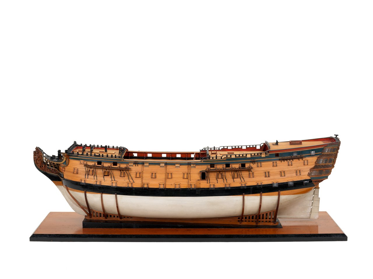
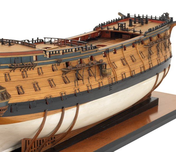
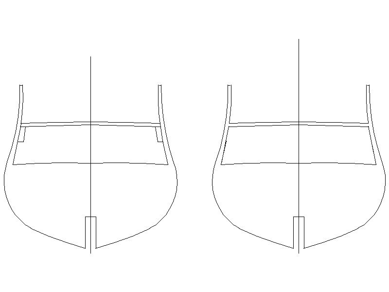
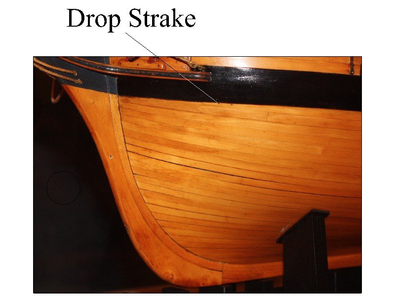
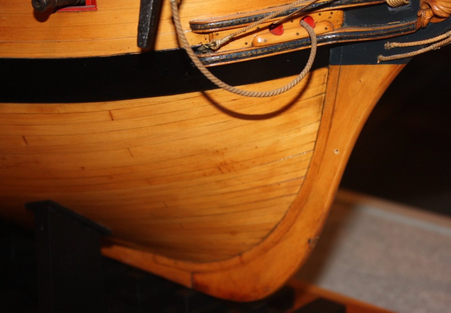
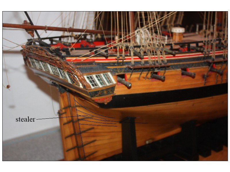
You have brought up an interesting idea that could really help members on their quest for a model kit to purchase. This is probably just a terminology thing. Drop strakes are not uncommon at the bow but if stealers are used, they are typically found at the stern. They are really two different things. I suspect stealers could be used at the bow if the planks are not spiled or otherwise pre-shaped but that would be highly unusual. Looking at your build log (your deck planking looks super, especially for a beginner) there are no pics of the "stealers" that you mention. Below are photos of contemporary models, two with a drop strake at the bow from RMG Collections and one with a stealer aft from the Rogers Collection at Preble Hall. The stealer is hard to see in the photo so I outlined it in black. My bad on the focusing when I took the pic. Allan
-
NAIAD 1797 by Bitao - 1:60
allanyed replied to Bitao's topic in - Build logs for subjects built 1751 - 1800
Bitao In making the jig, in order to drill the holes that hold the three pins, did you use a rotary table on a drill press or a mill? Getting them perfectly placed would be a nightmare otherwise. I will definitely give your method a try in the future, thank you very much for sharing your secret!! Allan -
Victory
allanyed replied to Jake 1948's topic in Painting, finishing and weathering products and techniques
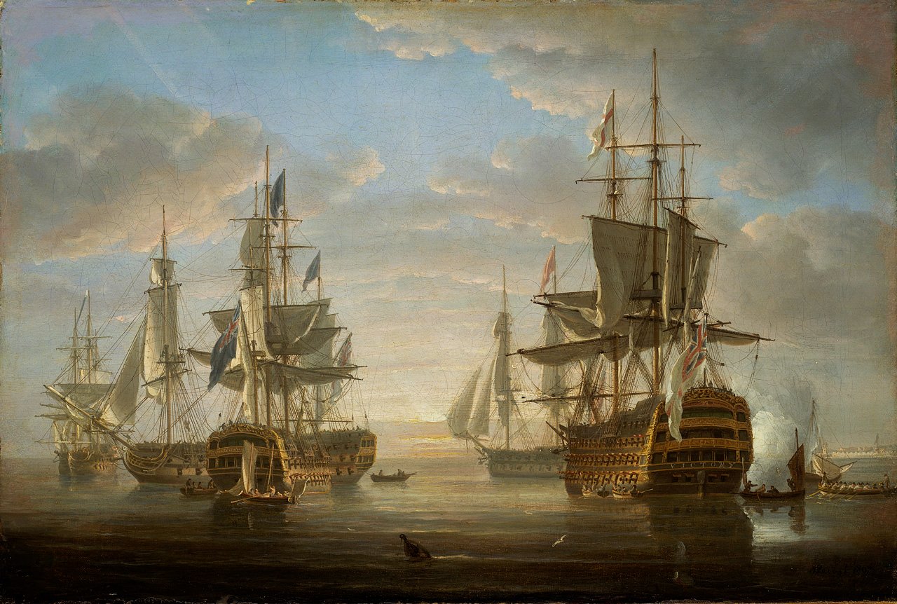
Hi Jake, The line of the gun ports follow the line of the deck as would be normal. The wales usually did not follow the deck line. As a result, some lids sometimes had two colors on the outside as seen in the contemporary model from RMG of Victory as built in 1765. (pics below) This is in contrast to the Popock painting from 1807 which is more in line with the Stanfield painting. The model in the photos below is 40 years before Trafalgar so the paintings may be the path to follow. Pick your poison.😀 Allan