
chris watton
-
Posts
2,334 -
Joined
-
Last visited
Content Type
Profiles
Forums
Gallery
Events
Everything posted by chris watton
-
 Looking good Vane! Those fragile stern frames were a headache for me. I didn't want to make them so thick that they would draw the eye from the rest of the model, but also needed to be robust enough to take the stern and side patterns. I could not use any kind of wood due to grain problems, they would break even easier and more often. This is why they are MDF, and also why I made sure in the instructions to tell the modeller to glue the stern patterns to the frames ASAP. The original designs for the 4 stern frames was a lot more robust, but found their oversized protrusions too out of kilter with the general fidelity and scale of the model overall - kind of like putting a 48th scale capstan on a 64th scale kit.. But, they are fragile, but just on the right side of acceptably so, I think.
 -
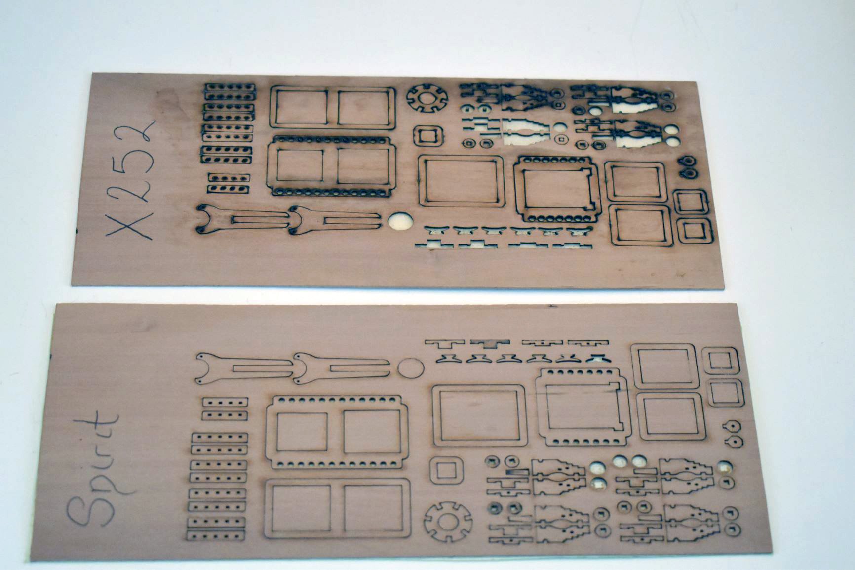
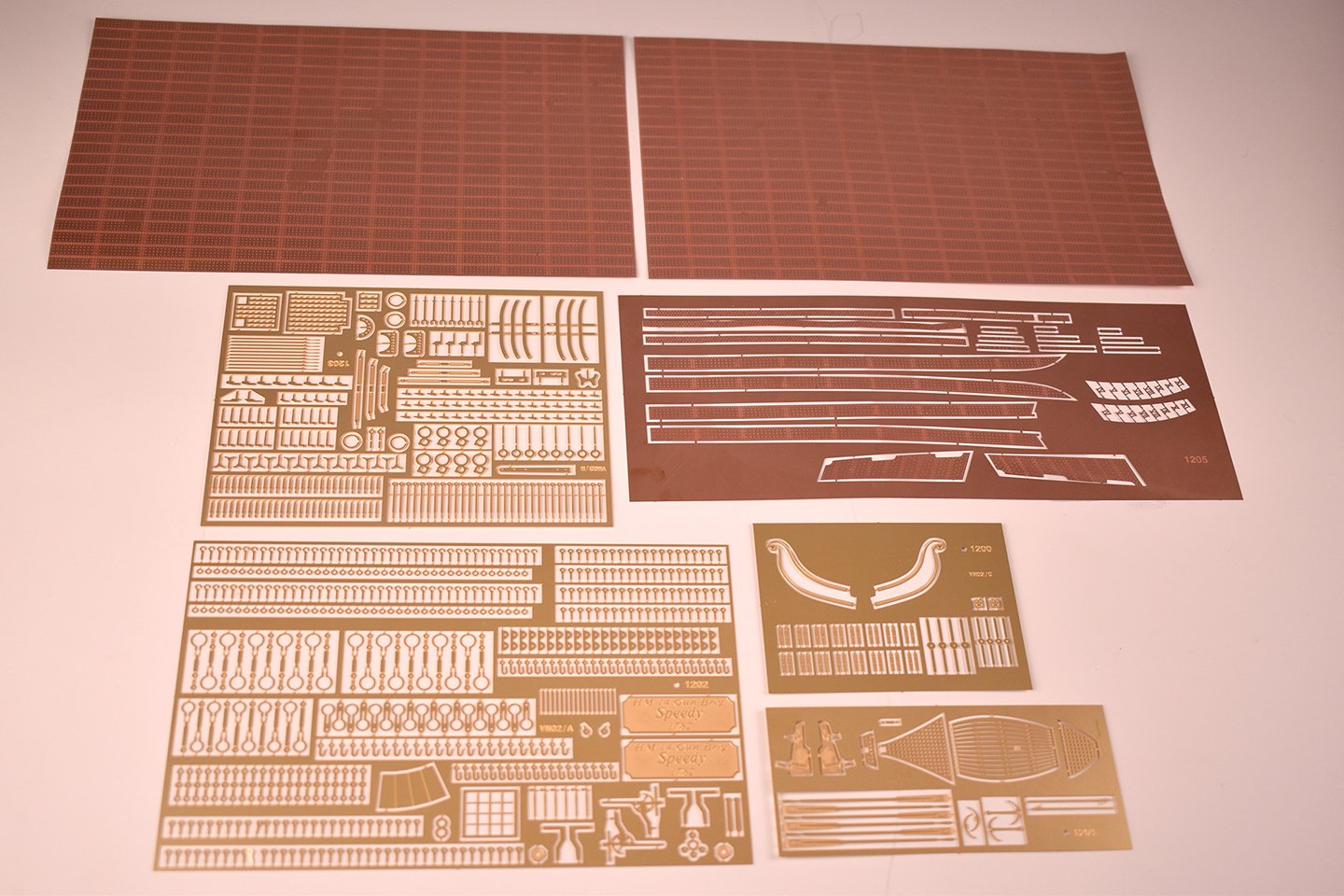
I just received 20kg worth of Speedy photo etched brass and copper parts, all look great. All components for the Speedy kit are now with me, as stated above, the kits will now be completed and shipping booked over the next few days.
-
Hi Jorge, Not in the immediate future, no. At the moment, I would not be able to justify the set up costs for another two figures in those scales. Not yet, at least.
-
OK, I have booked the UPS pick up for Speedy PE parts from Italy today, and I should receive them tomorrow. They will need to be prepared for each kit, so all ordered kits will be ready to send on Monday, all being well. I have also been accepted for the funding of a high end laser/engraver machine, which I will be getting within the next few weeks. This is quite an investment, but feel it is essential if I am to continue.
-
Compared to the soft and malleable Tanganyika, it's like strips of steel!
-
I always use thick CA for second planking, and planking decks!
-
I would honestly use the extra thin ones that come with the kit. These are Amati special pins and are perfect to hold the first planking to the MDF bulkheads without splitting any materials.
-
Just had word from the Italians regarding Speedy PE. It will be ready for me to pick up from Italy on 5th (next Thursday), so will receive the parts a couple of days after this. I need to then prepare each set for the kits and simply add them to the already made up kits for each customer. All Speedy's will be shipped between 10th-13th December, so all in time for Christmas.
-
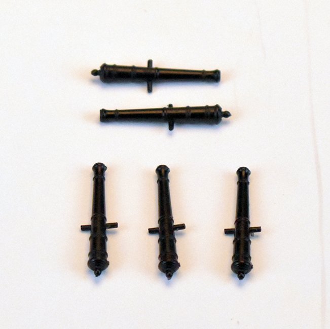
I will in time, I can say that it will be quite pretty! Yesterday I had 10 sets of Alert 6 and half pounder cannon barrels arrive, with another 30 sets being cast now. These will now be offered as an optional extra with the original Alert kit, and will be included in the upcoming second edition Alert kit, which will have a higher price to reflect the high cost of the resin cannon and pearwood laser cut parts and 0.8mm birch ply deck.
-
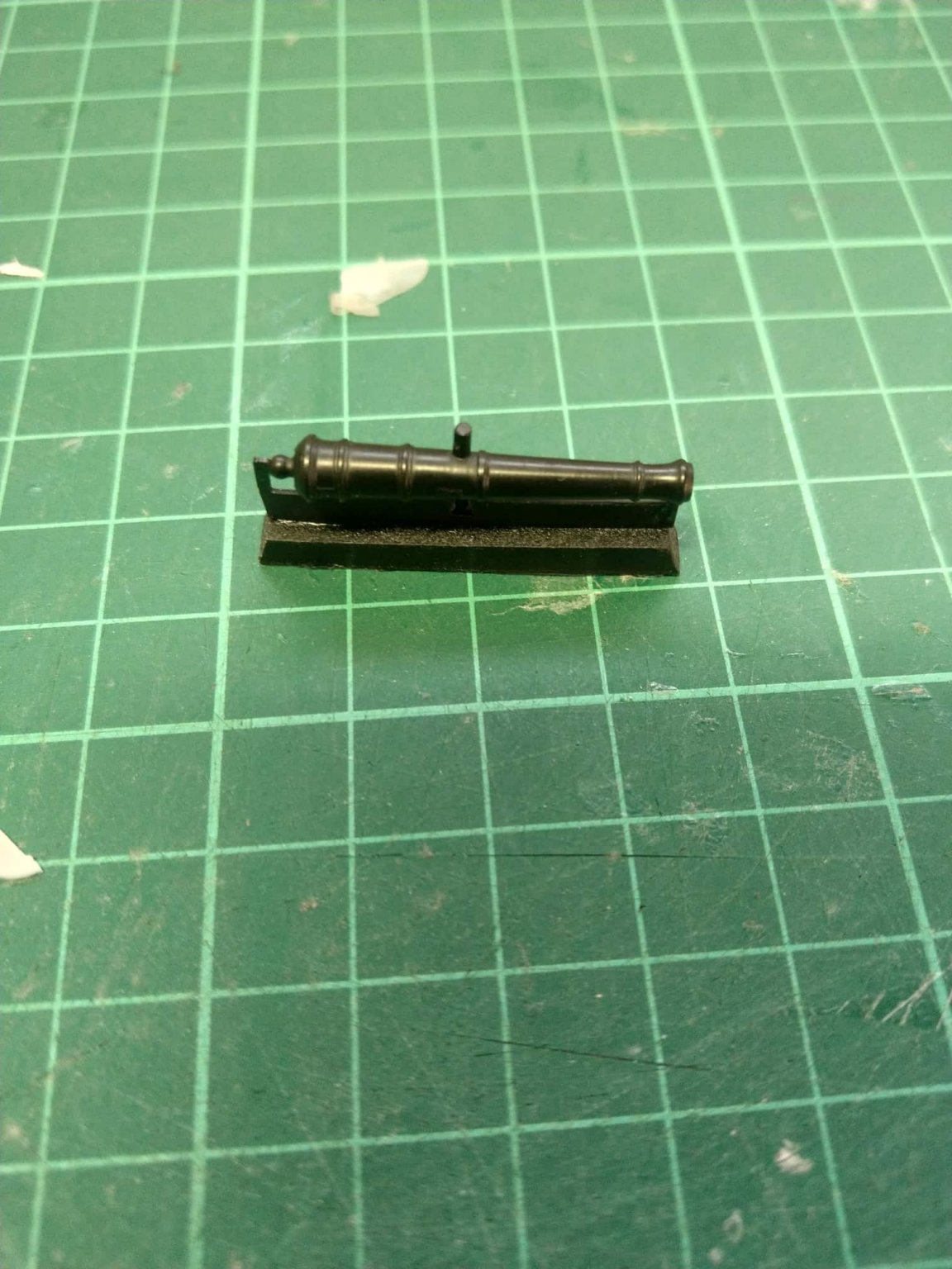
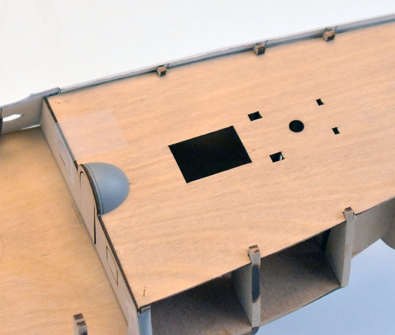
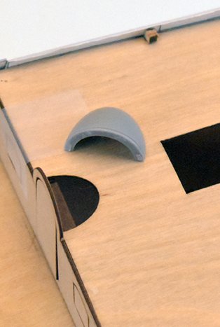
Lots of stuff arriving this morning! Just had another 30 Speedy kits worth of resin cannon, this time in black resin (Alert black cannon arriving Wednesday) Also included is a resin casting for the domed canopy sample for the third kit. There was no way I was going to assume the customer would want to make this part out of wood. It was likely copper anyway.
-
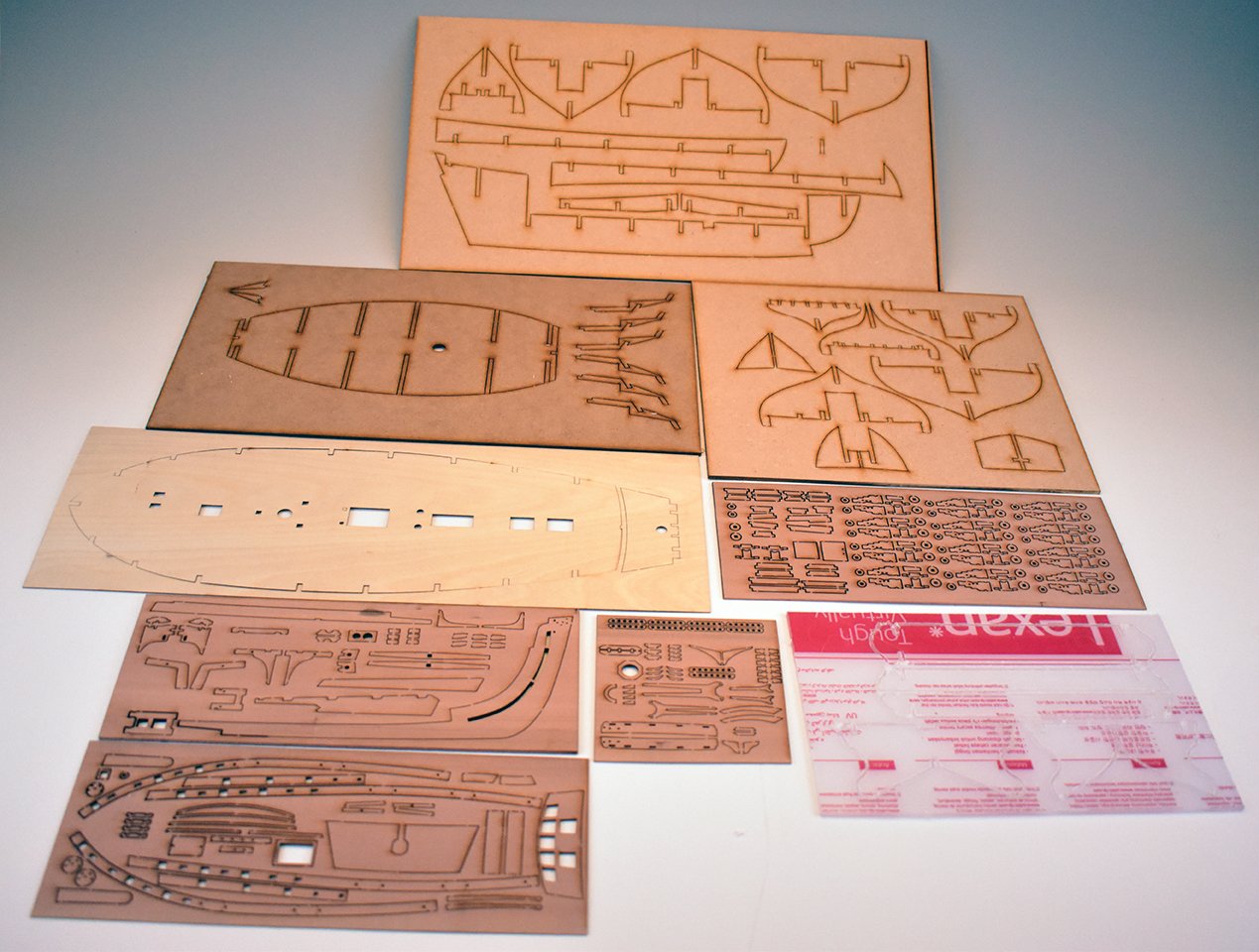
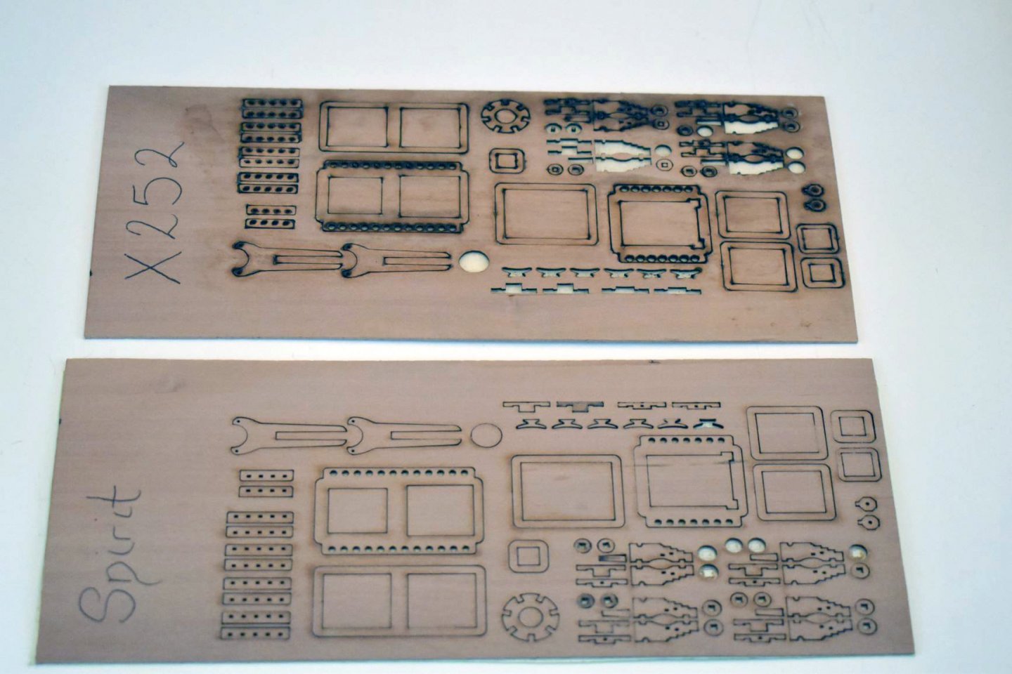
I just had another batch of laser cut parts for Speedy arrive, this time the premium version with basswood laser cut sheets, and they look very nice. Also, I had a sample set of the Alert complete laser cut parts for a top end version of Alert. I made minor changes to some parts, and the deck is now moved to 0.8mm plywood, and the wooden parts are now in pearwood. I added a couple of pics of the Alert samples, one with all of the sheets, and another with the changes.
-
Fender, chesstree?
-
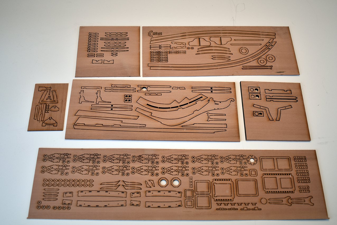
Just took a couple of pics of what's inside the box. This is Master Shipwright kit number 9, and is just awaiting the photo etched parts to be added, so when they arrive, they can be shipped immediately. Because everything is protected in bags, I included what cannot be seen again. (Main component parts). I should find a clear fittings tray, to show off the blocks, cannons etc. but they are all in that little box, quite safe..


-
Thank you! My wife has been packing the Speedy kits today and I can tell you, the box is quite heavy (even without the PE). I do not think there is any part of this kit that I am not happy with.
-
kit review 1:32 Fifie – The Scottish Motor Fishing Vessel by Amati
chris watton replied to James H's topic in REVIEWS: Model kits
The drawings were based on plans from James Pottinger (also other drawings of like vessels), with whom I liaised with when developing the model. This was 12 years ago now. -
kit review 1:32 Fifie – The Scottish Motor Fishing Vessel by Amati
chris watton replied to James H's topic in REVIEWS: Model kits
The wheelhouse was designed according to the real plans exactly. It was a small structure, as the originals didn't have a wheelhouse at all. It is only when they stuck in an engine they added this. (They originate from pure sailing vessels) The name I gave this was Rob Roy, it was also on the (now blank) nameplates that appear on the sides of the model. I think Amati was worried about copyright over the name, although I have no idea why. -
It is, and I am glad I insisted on them using one of my files, rather than their own which would bare no real resemblance to what I need the machine for. That is the difference between an 80W laser (top pic) at half the price of the narrower beamed 40W machine (bottom pic). I did forget to add the retention tabs to each part, though, which is why some bits are missing, nothing to keep them in place once cut...
-
Yesterday I had a couple of samples of laser cutting from a sample file I gave the company and 1.5mm pearwood I also supplied. I want a certain high spec laser machine, recommended to me by someone who already has one. The company that sells them asked what the machine will be used for. (80% cutting and 20% engraving). He recommended a cheaper version, can you tell which is the cheaper version from the samples (or did they over-egg it as a ruse...). Clearly, the 'Nuclear' option is out of the question, so it seems I will go for my first choice and what was initially recommended to me, which suits perfectly the type of work I want it to do. It will be quite an investment, but I really do feel that I need one, looking forward. As I mentioned, I have ordered a LOT of pearwood sheet from Germany, which should arrive in the next couple of weeks. For my third kit, I am erring on having only one quality option, pearwood laser cut parts and pearwood second planking, with cast resin decoration for figurehead and stern and cannon, and laser engraved deck planking. Also, as I have mentioned, I shall be having 15 Alert kits done by the UK laser company with pearwood laser cut parts, a 0.8mm ply sub deck (kit will still have boxwood deck planking) and cannons in black resin. I shall have one sample kit ready next week, so I can check it over. Price will be £220 with the different materials and resin cannon. Ultimately, I want all kits to have the same quality parts and materials, and it seems that the combination of pearwood laser sheets and pearwood second planking, together with quality castings is what most want (I would too, to be honest).
-
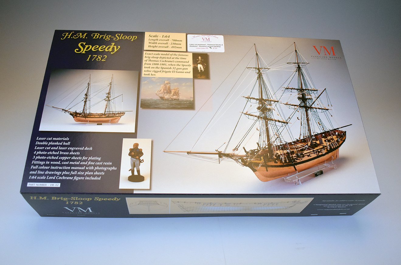
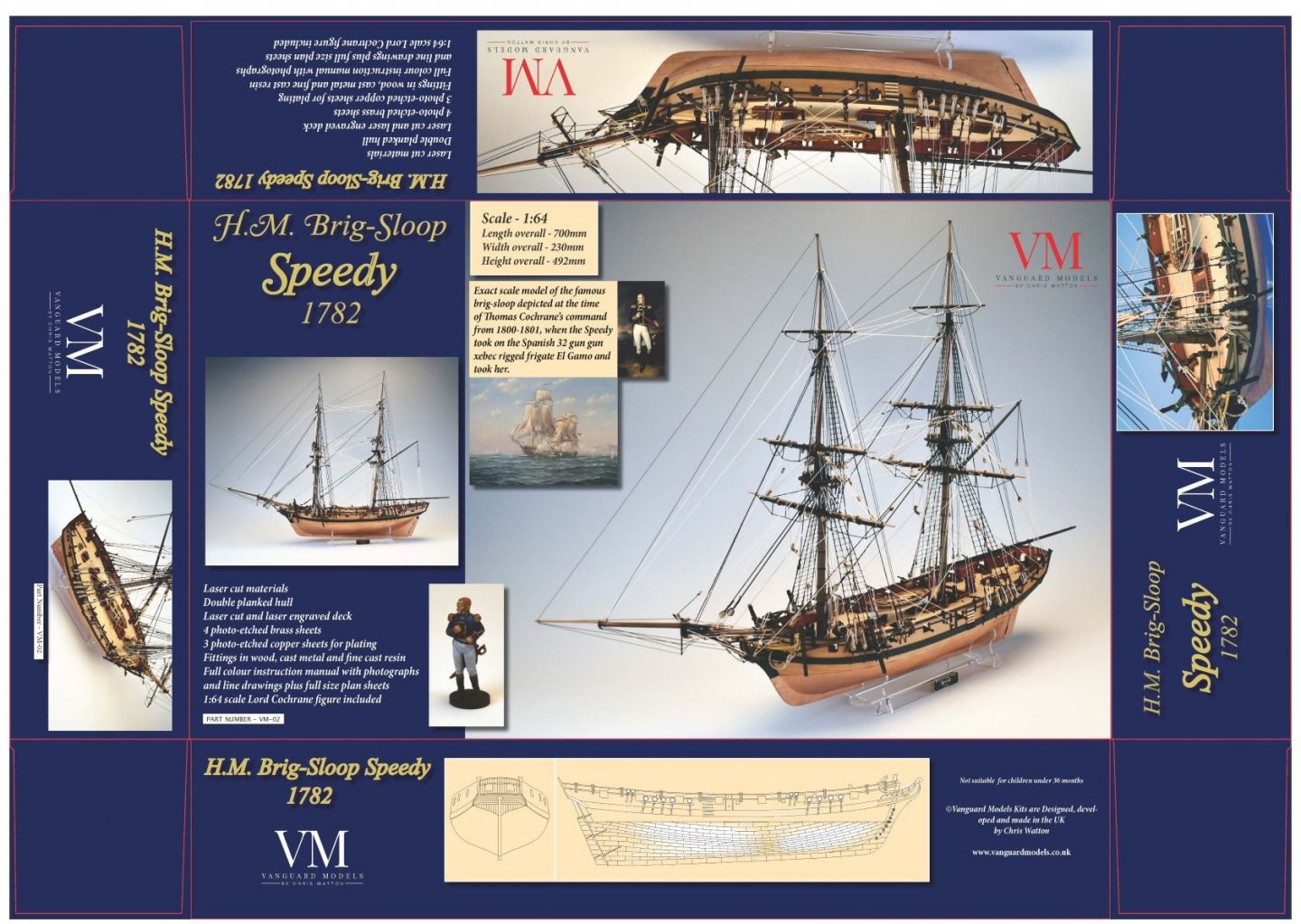
Dimensions of completed model are: Length - 700mm (Around 27.5") Width - 230mm Height - 492mm
-
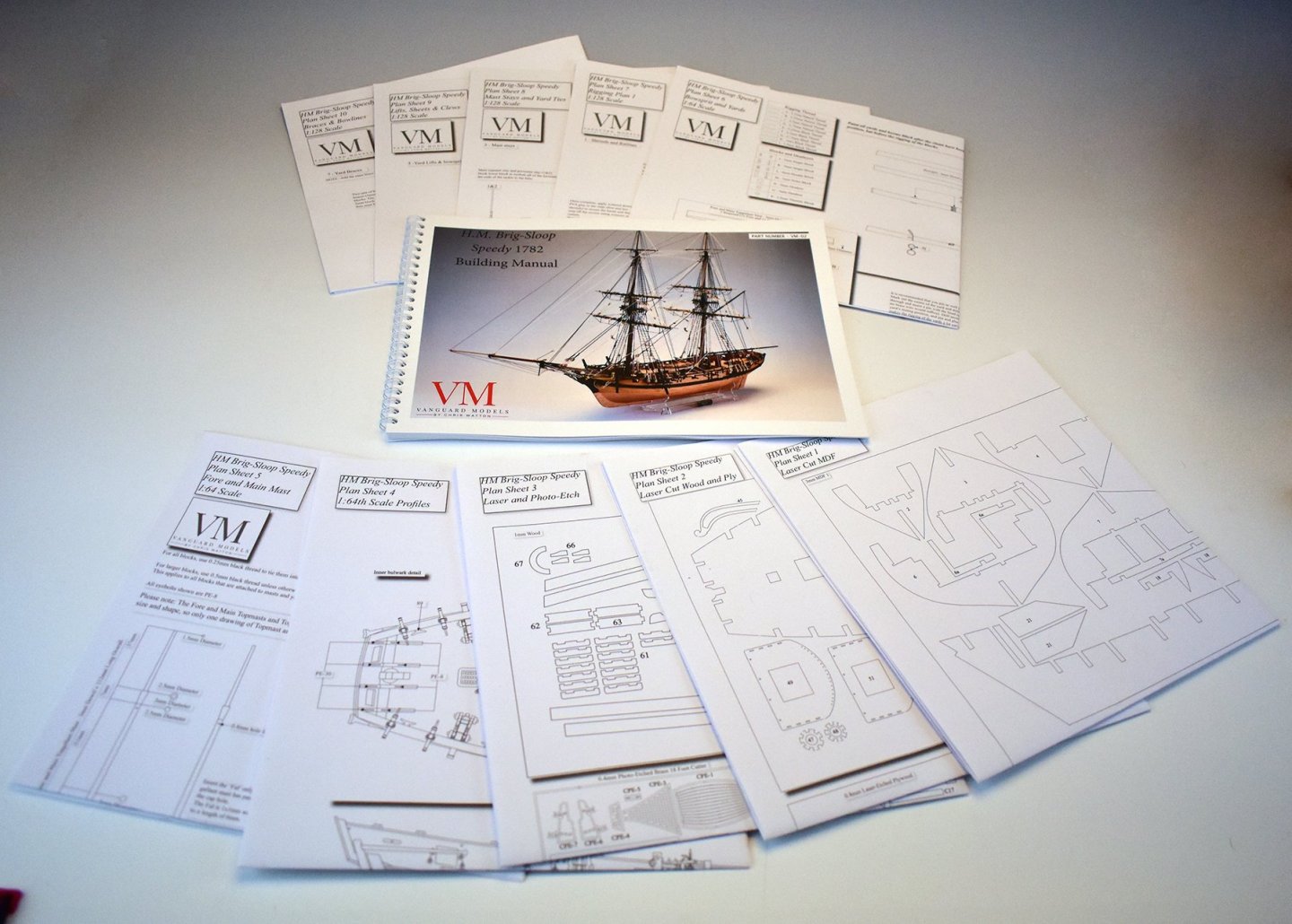
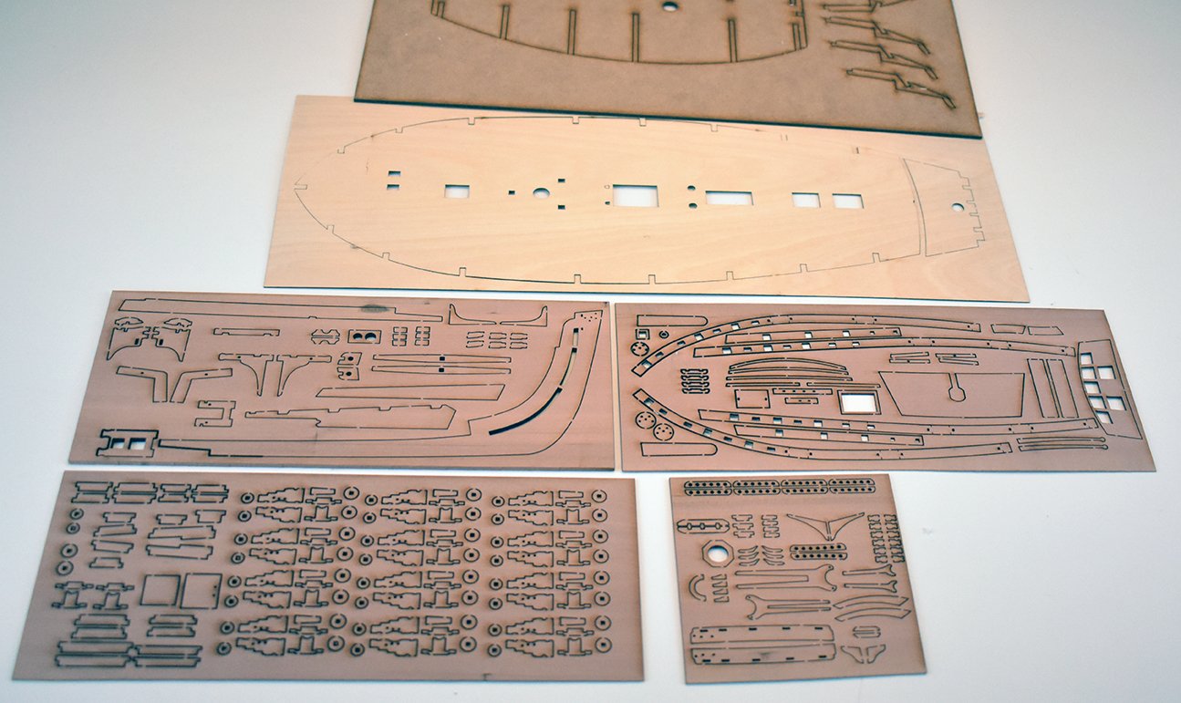
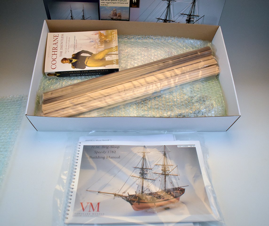
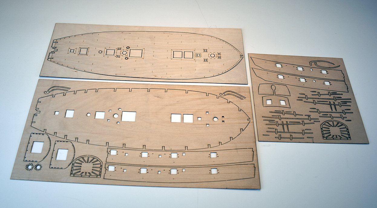
I will pull the text I wrote for Speedy page: There are three versions of the kit to choose from, but all have the following features: 14 sets of laser cut materials, including a laser cut and engraved deck 7 separate photo etched sheets in brass and copper Copper plates for hull below waterline 18' Cutter Double planking in limewood and a choice of second planking woods highlighted below Walnut dowel for masts and yards 10 separate rigging thread sizes in black and natural 14 cast resin 4-Pouunder cannon and 20 cast resin half-Pounder swivel cannon Cast resin 1:64 scale figure of Lord Cochrane himself 60-page full colour building manual and 10 sheets of 50x70cm plan sets Two cradles, one for when building and a clear acetate display cradle for the competed model All other materials and fittings required to build the model as shown. The version differences are: Standard – Laser cut MDF, 0.8mm ply and basswood parts and high-quality Tanganyika strip for second planking. - £225 Premium – As above but pearwood strip for the second planking. - £245 Master Shipwright Edition (Limited to 20 numbered kits) – £340 As above but with boxwood second planking Pearwood laser cut parts instead of basswood Machined pearwood block and deadeyes (Master Korabel blocks and deadeyes) The book Cochrane the Dauntless: The Life and Adventures of Admiral Thomas Cochrane, 1775-1860 Paperback by David Cordingly, which contains a whole chapter relating to Cochrane and the Speedy. ___________________________________________________________________________________________________________________________________________________________________________________________________________________________________________ These are the initial release versions and, because I am being very fussy with the laser cutting, the initial releases have all the cutting done in the UK (but at much higher cost), so I will only have 19 Master Shipwright (pear laser) kits and 15 standard/premium (basswood laser) kits upon release. I receive the 15 laser cut sets for Speedy in MDF, 0.8mm ply and basswood from my UK supplier on Monday (Quite literally just paid for that order over the phone, after just being told the parts are ready to ship). I am just waiting for production PE parts from Italy, which are being done now and expect my courier to pick them up either next Friday or the week after at the latest. I will open the Speedy for pre order soon, as everything else for the Speedy kit is with me and I am happy with the parts, and I know the PE is being done after I gave the go ahead yesterday morning once I checked them over (production samples).
-
You should be very proud of that, you have done this absolutely from scratch and it's brilliant!
-
Thank you! I would love to know how many are interested in the Master Shipwright version (boxwood planking, pearwood blocks and laser cut parts etc.), so I know how many initial kits to make up. If anyone is interested in that one, please let me know, cheers.
-
Yes, I have 10 sets arriving next Tuesday, followed by another 30 sets the week after, and will be on sale separate from the kit.
-
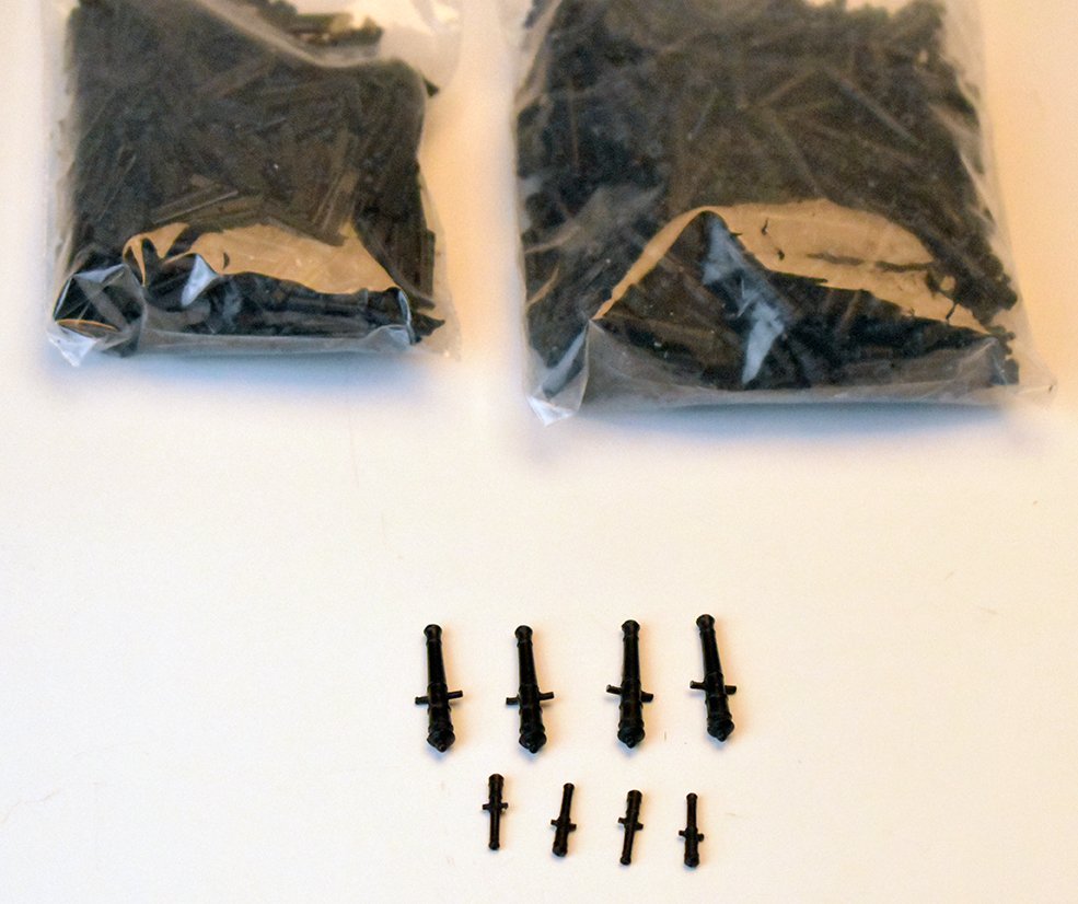
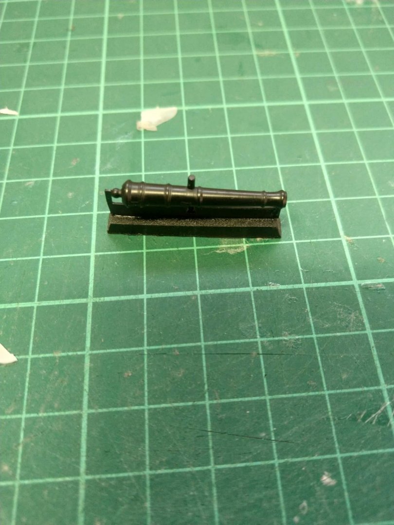
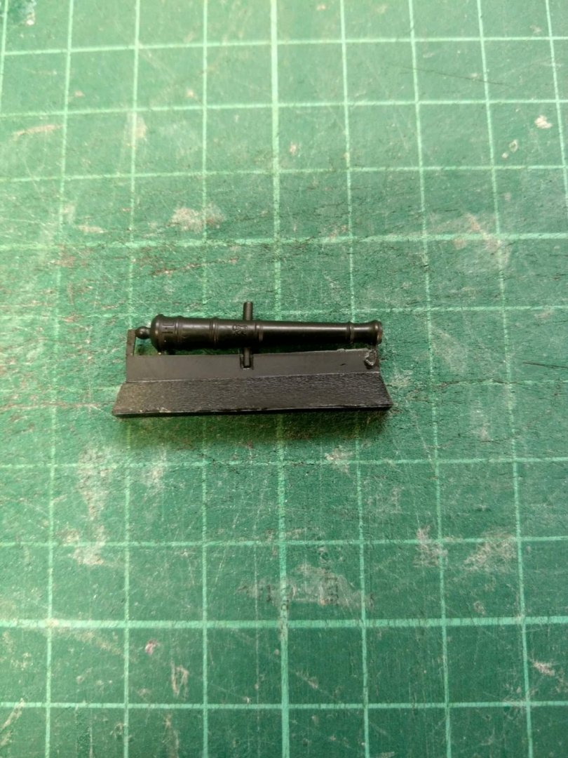
And here is the new 6-pounder Alert cannon, cast in black resin, which I will be receiving in the next few days.
-
Right, I had the sample photo etch and laser cut parts from Italy arrive yesterday. I wanted samples because I needed to be sure the production parts for Speedy are all as I want them. There was a problem with one of the PE parts when building the prototype, which has now been fully rectified, so have given the go-ahead for the production PE sets, which should be with me by the end of next week. The laser cut parts I am still not entirely happy with, and have asked them to rectify the problems I highlight or not do any. In the meantime, I have 20 full sets for the special pearwood version of the kit and another 15 sets arriving on Tuesday for the basswood version, all laser cut in the UK. This is the reason I wanted to wait, as I want to make sure I am happy with everything in the kit box. Essentially, I have everything I need apart from the production PE parts, which will be with me next week. (although technically, I do have one full kit set as the sample parts for the PE are great) I know I said end of October/early November, but the Italians took a lot longer than I anticipated, and I did insist on seeing sample parts for me to double check before entering production.