


CTDavies
-
Posts
55 -
Joined
-
Last visited
Content Type
Profiles
Forums
Gallery
Events
Posts posted by CTDavies
-
-
I‘ve ordered pearwood strips for the lower deck, which will probably only arrive the week after next. To keep myself busy I started something else.
This is going to be a loooong build (well at least it isn‘t a Victory) 😳😆
-
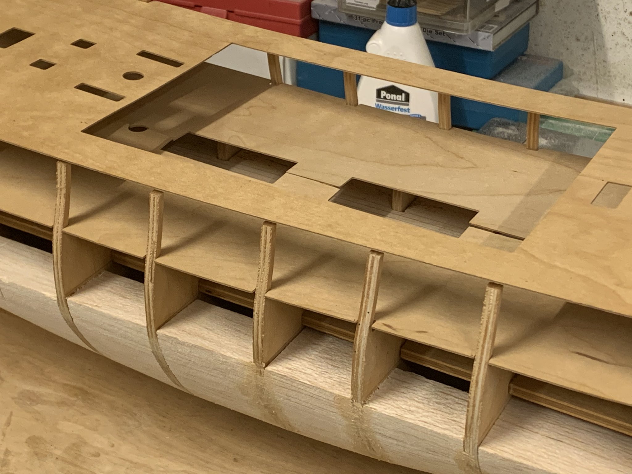
I have also noticed that part of the bulkheads might be visible through the open hatches. This will have to be fixed. But first I‘ll have to order a decent razor saw.
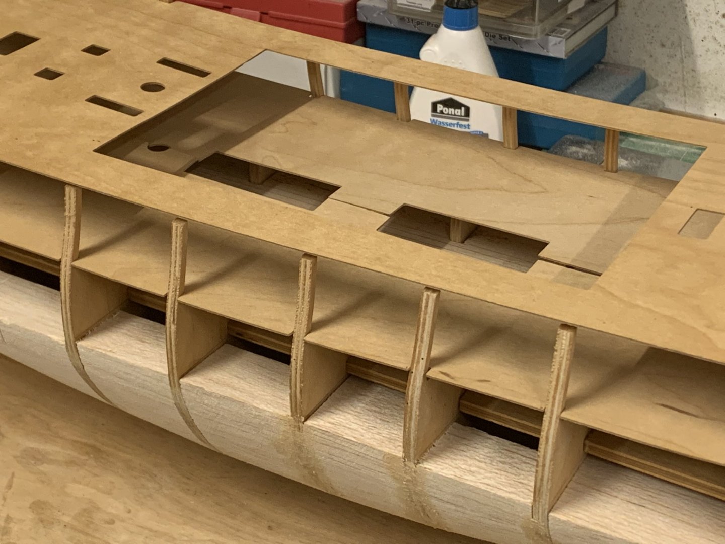
Per instructions the lower deck should just be painted in walnut stain, but I would like to take things to the next level here and plank the deck as far as it is visible and add hatches etc. Tosti writes that the planking outside of the Binding Strakes was done in Evergreen Fir which should add a bit of variety but only on the lower deck. As far as deck planking goes I‘m planning on doing everything in pearwood except the Fir decks which will be in Maple. Hull planking (if I get that far) will be Boxwood,
Chris
- KARAVOKIRIS, GrandpaPhil and Tigerdvr
-
 3
3
-
I‘ve just noticed on my brother‘s PC that the images are very large. This might be against etiquette so give me a day or two and I‘ll see if I can replace them.
-
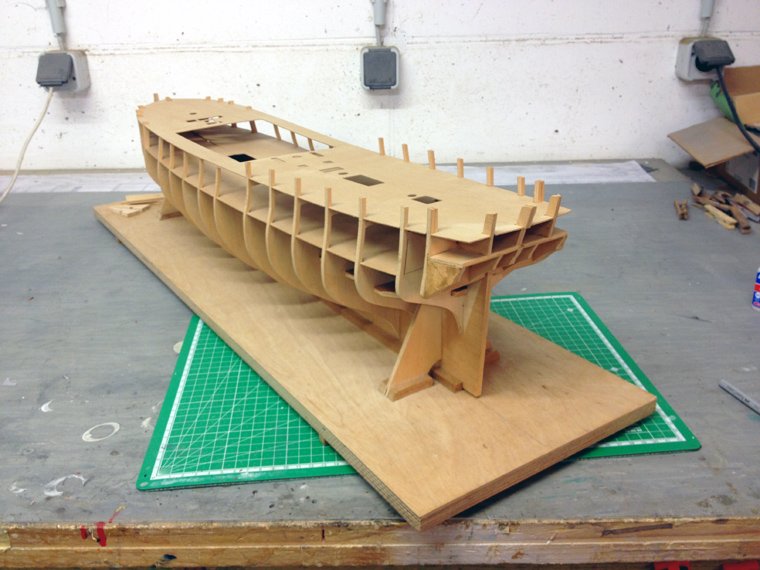
So after a break of close to five years, being inspired by Vanguard Models‘ Speedy (yes, I bought one), I decided to dust off the Diana and carry on where I left her.
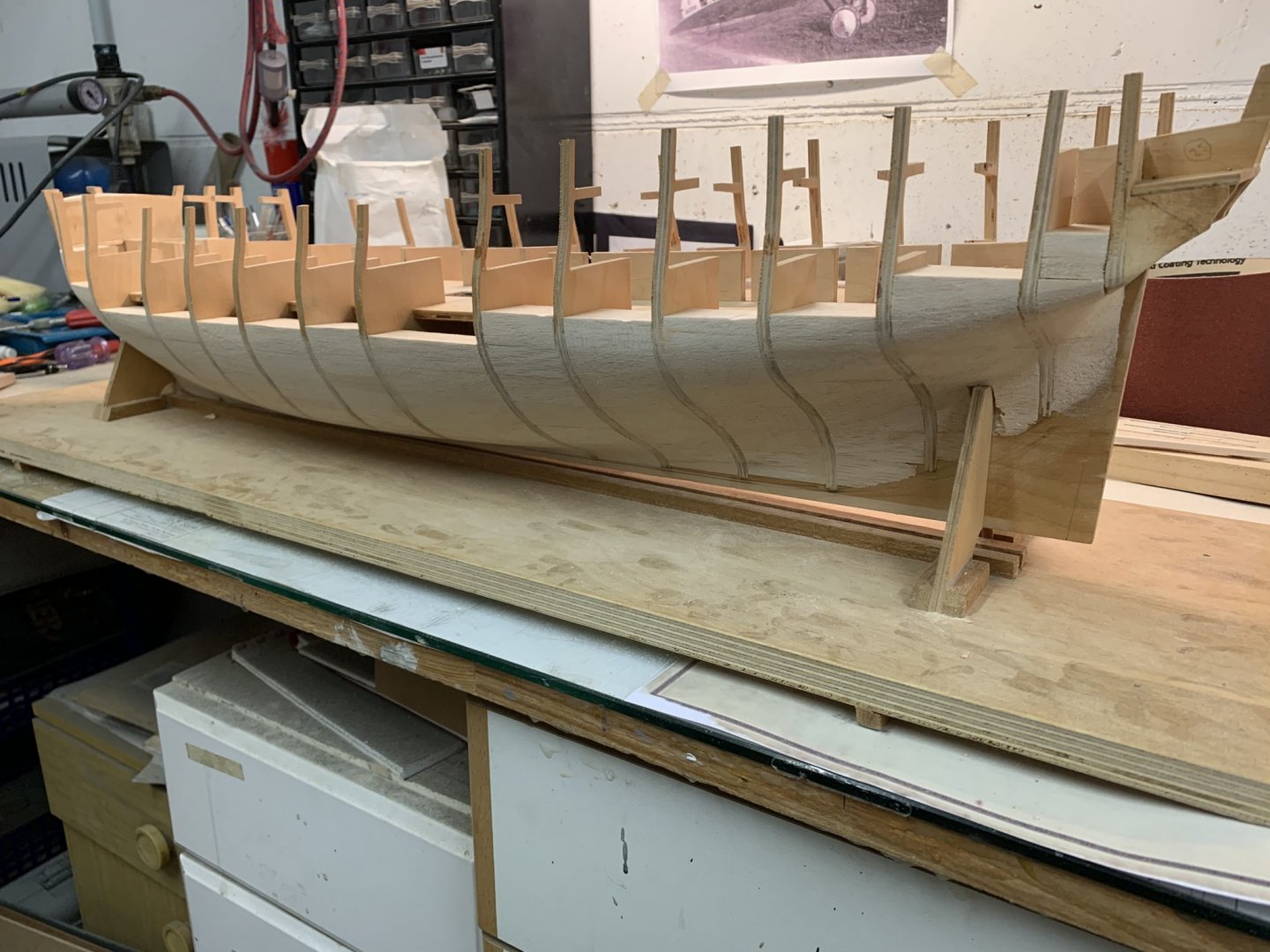
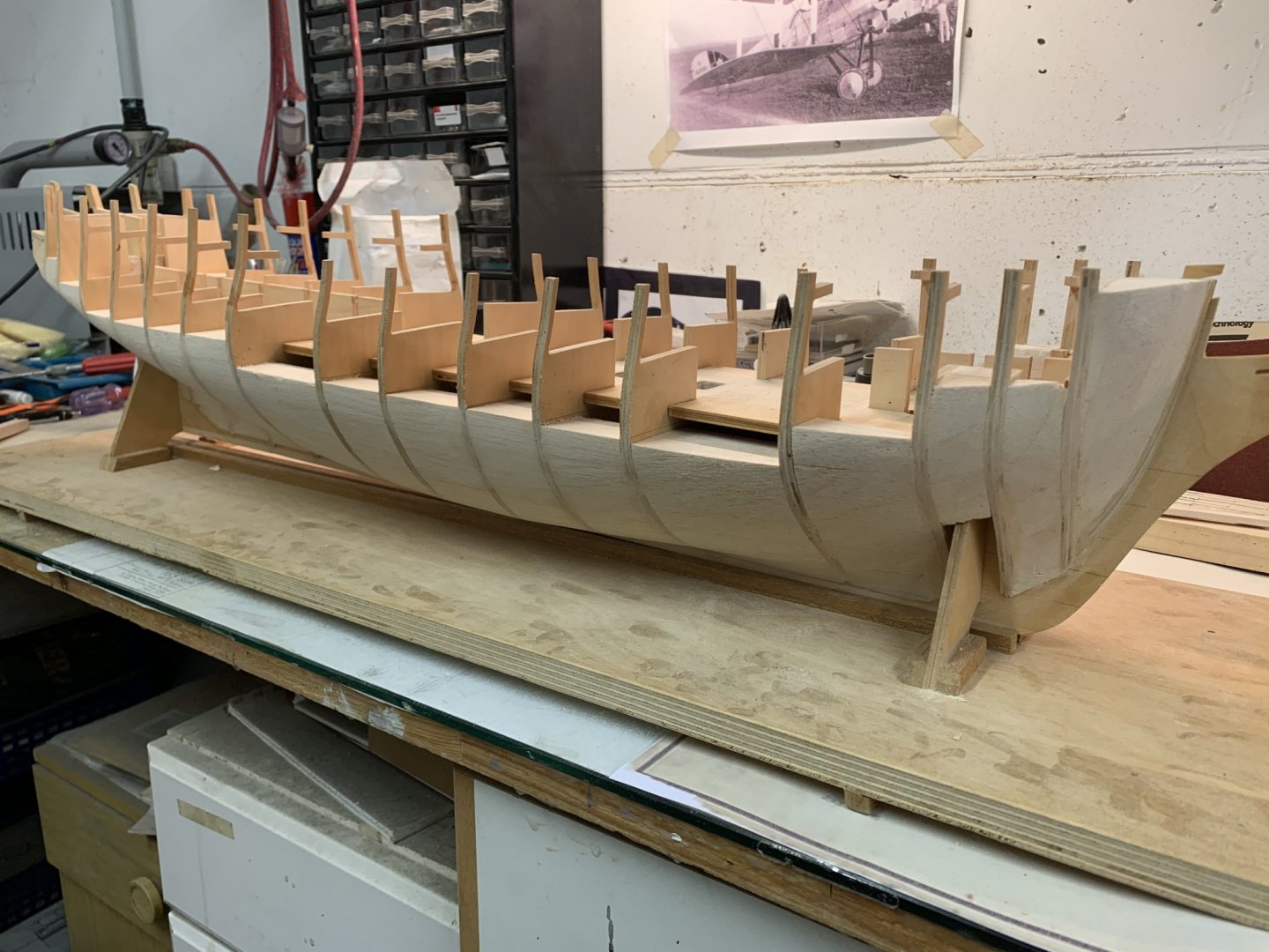
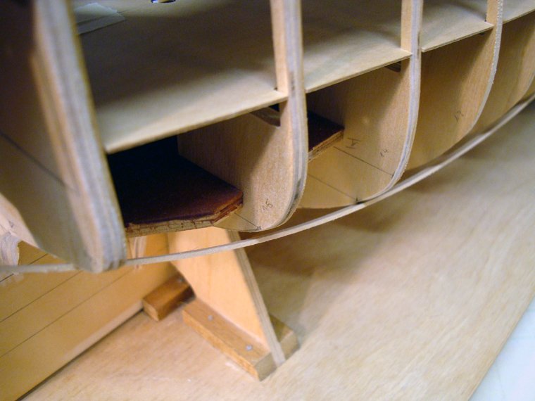
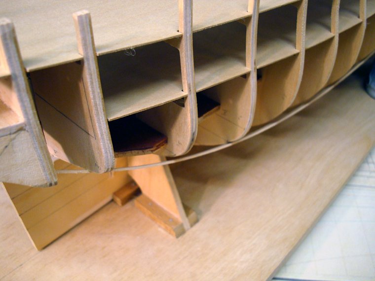
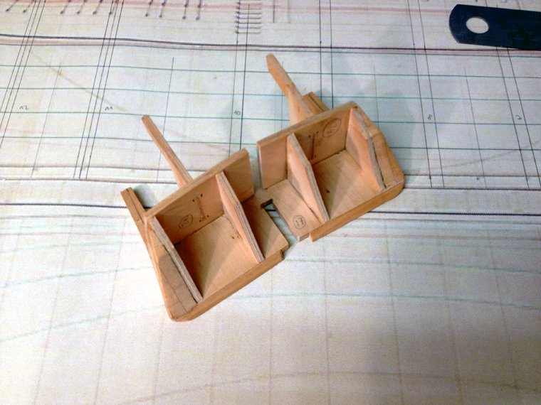
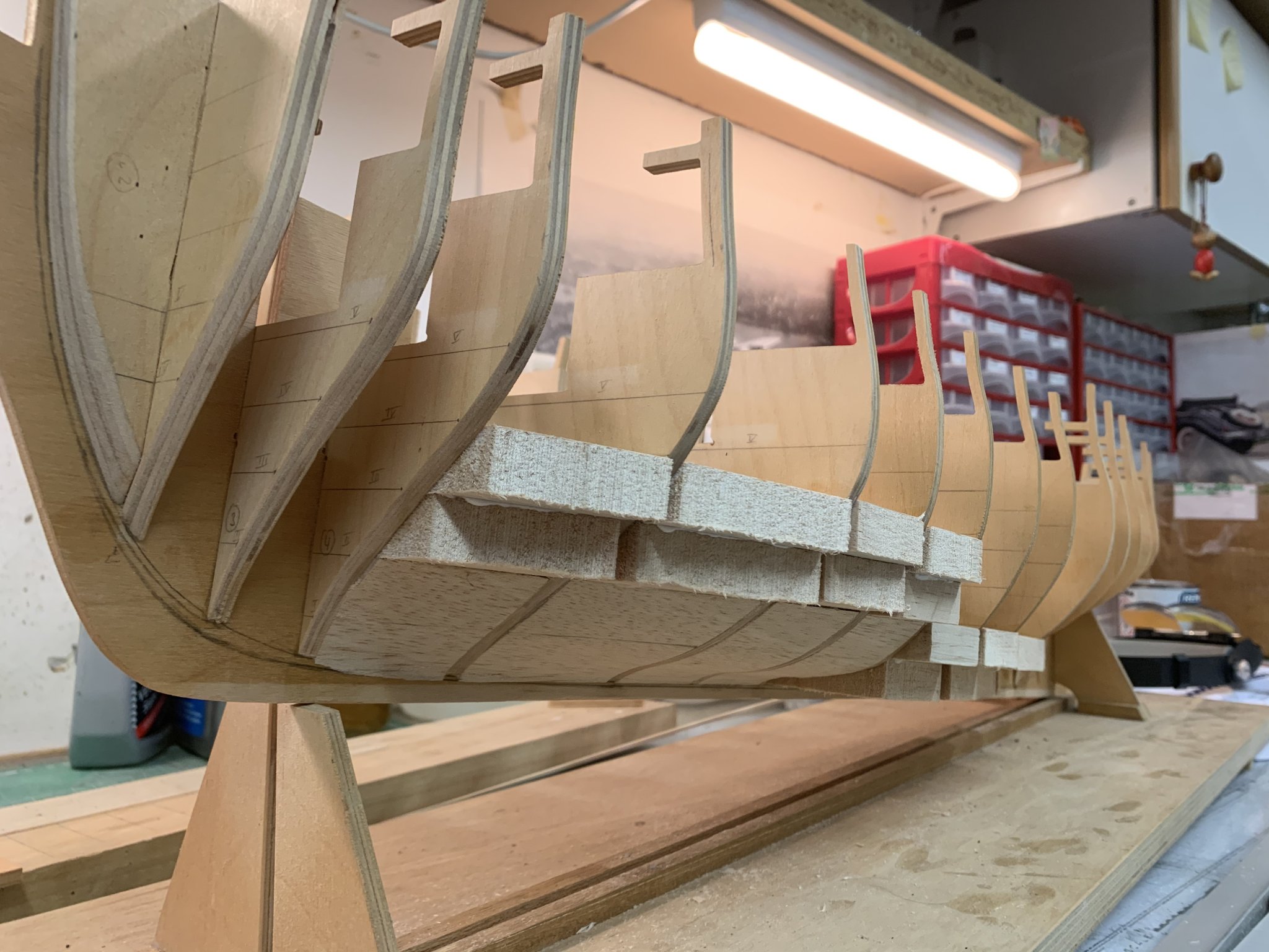
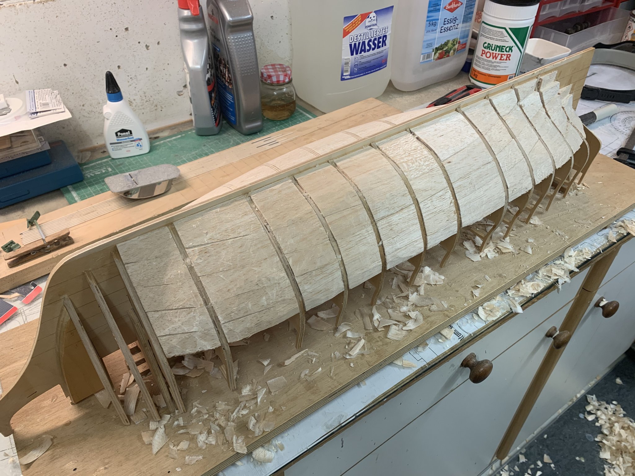
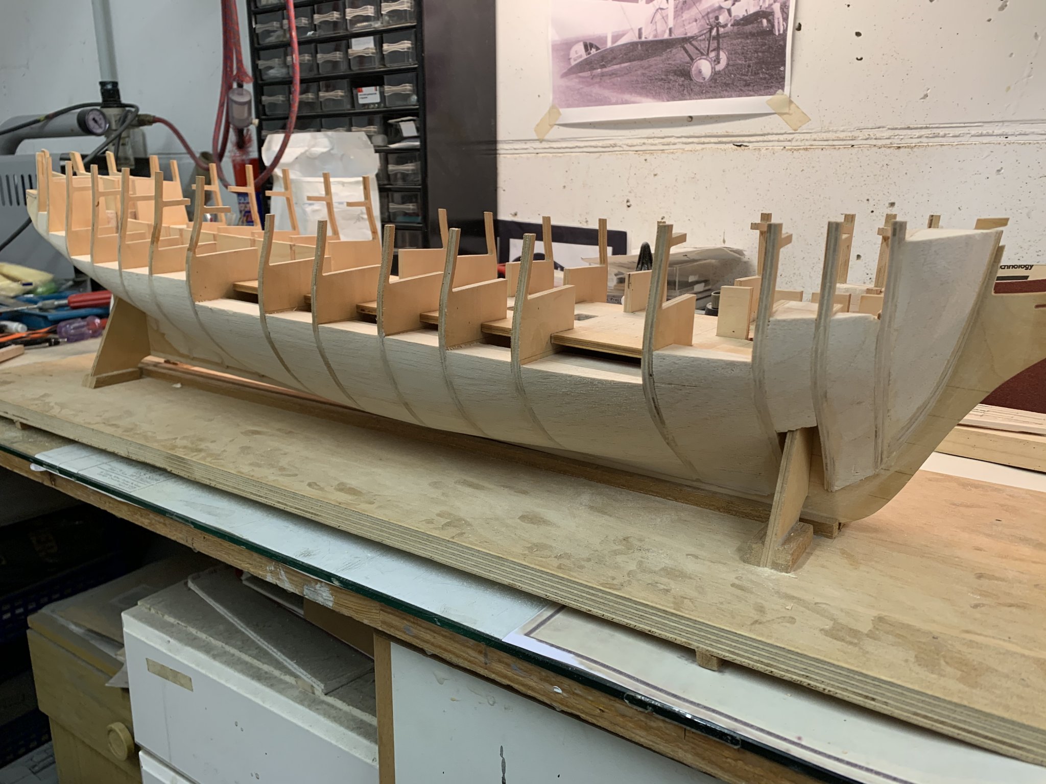
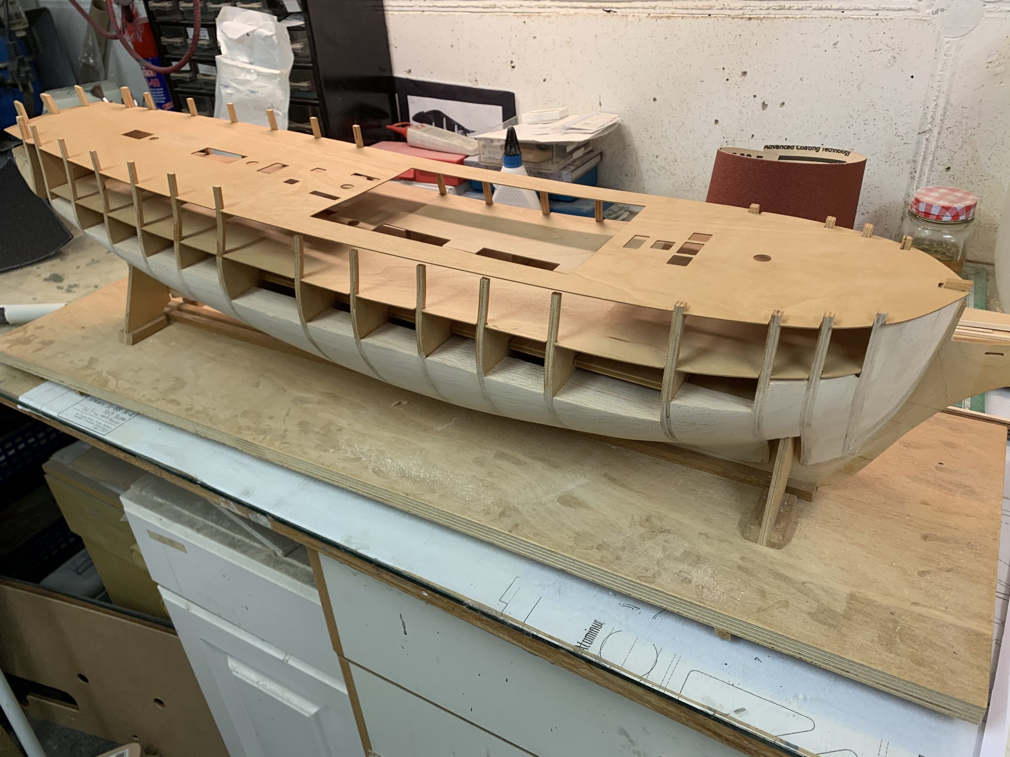
I had always had the intension of filling in the space between the bulkheads with balsa as, a) I didn‘t trust my planking skills and b) to check her hull after modifying the bulkheads the way I did. This was a slow process at first but started to move along once I got the hang of it.
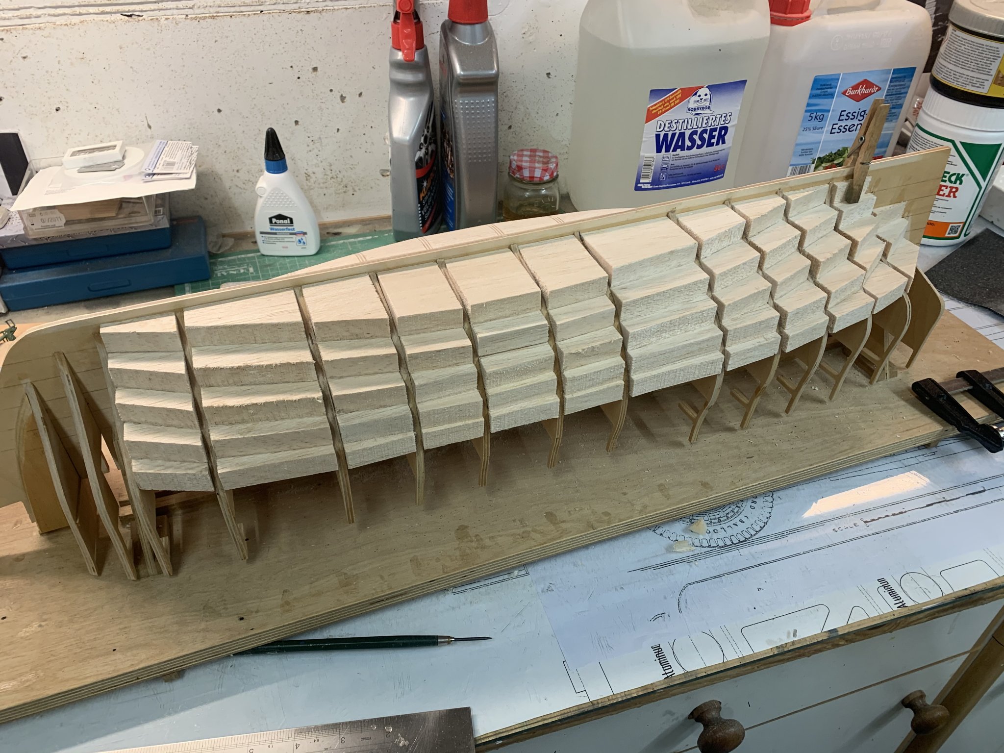
I found the best way to shape the infills was by carving...
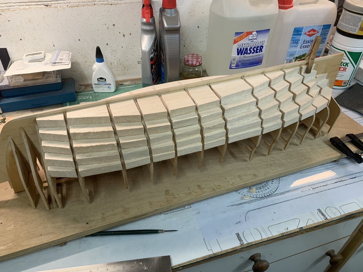

...and sanding with 40 grit sandpaper on a small plank

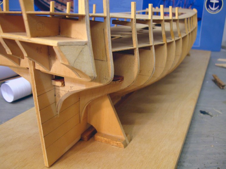
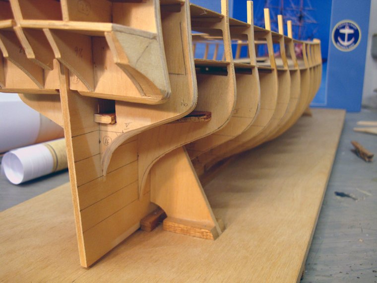
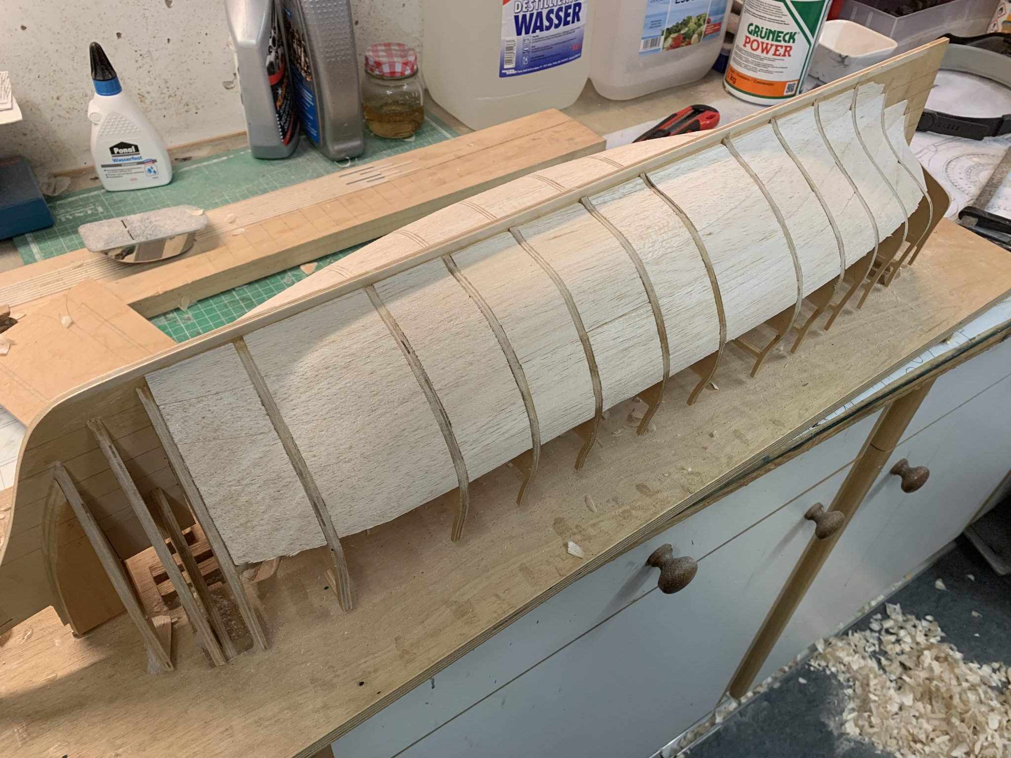
The bow and stern where also filled in
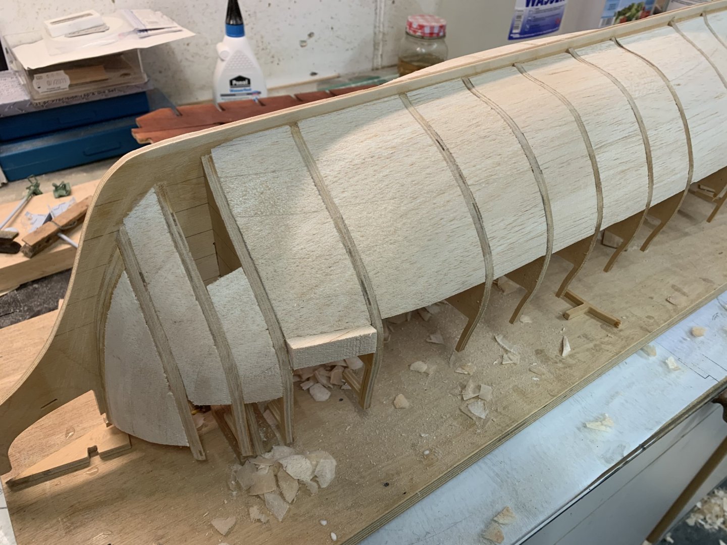
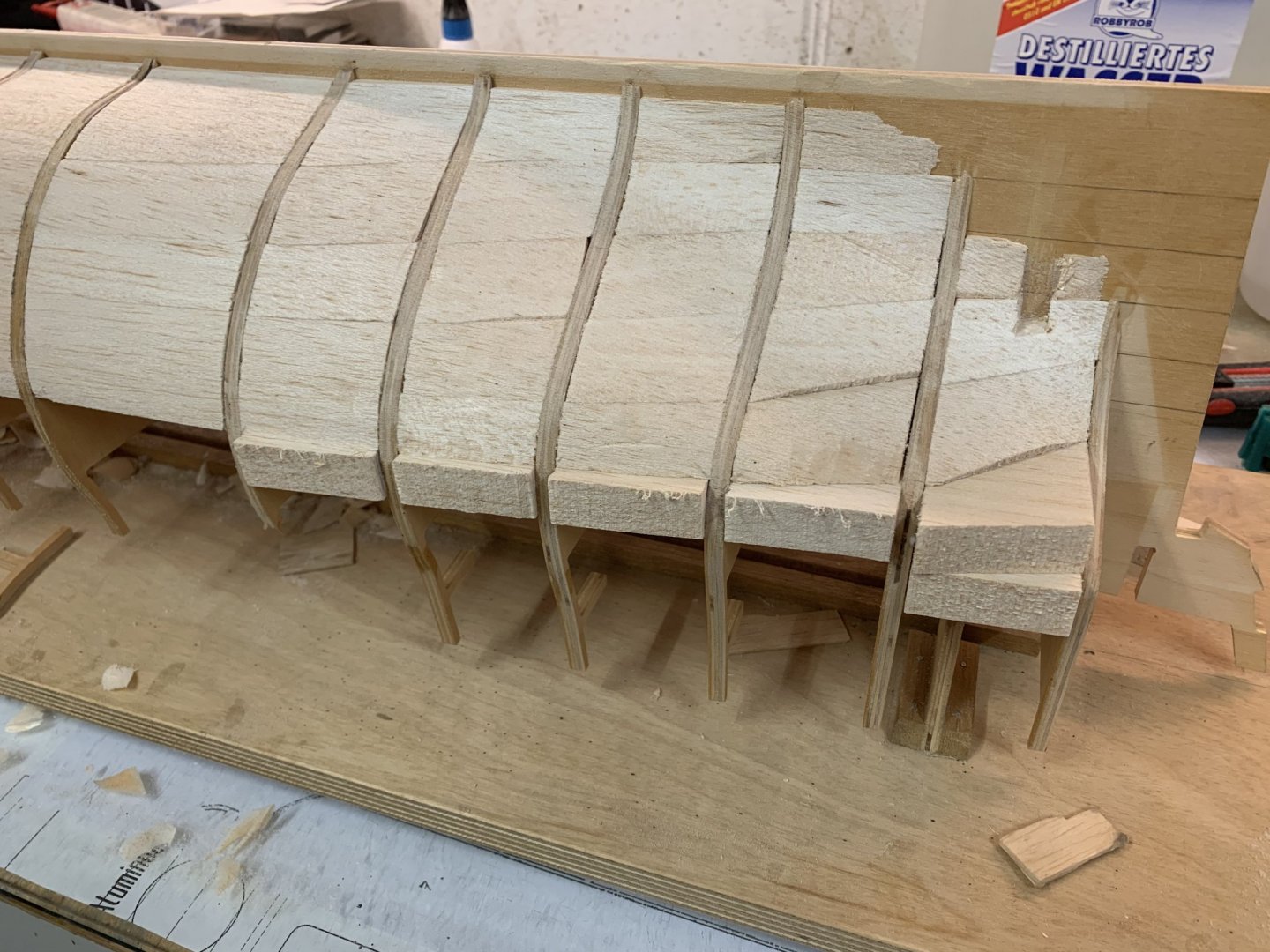
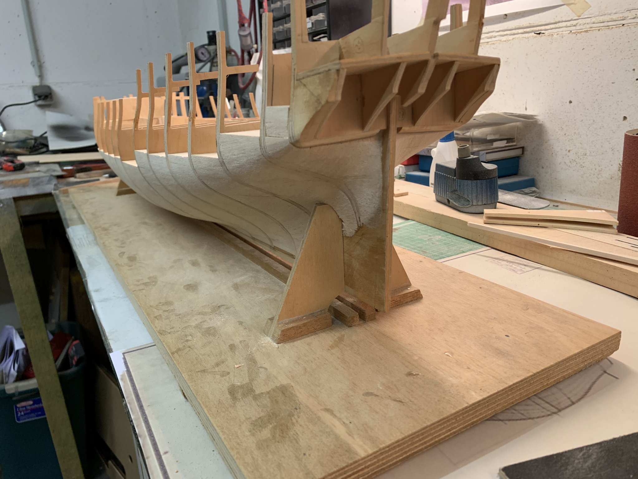
The thick lower deck wasn‘t in place when I did all this so I could turn her upside down and work on her the ‚Hahn‘ way. This was nearly a disaster as it was very difficult to get it to fit right.
In the end I also filled in the space between the very last bulkheads. The stern wasn‘t easy but manageable with a bit of planning and forethought.
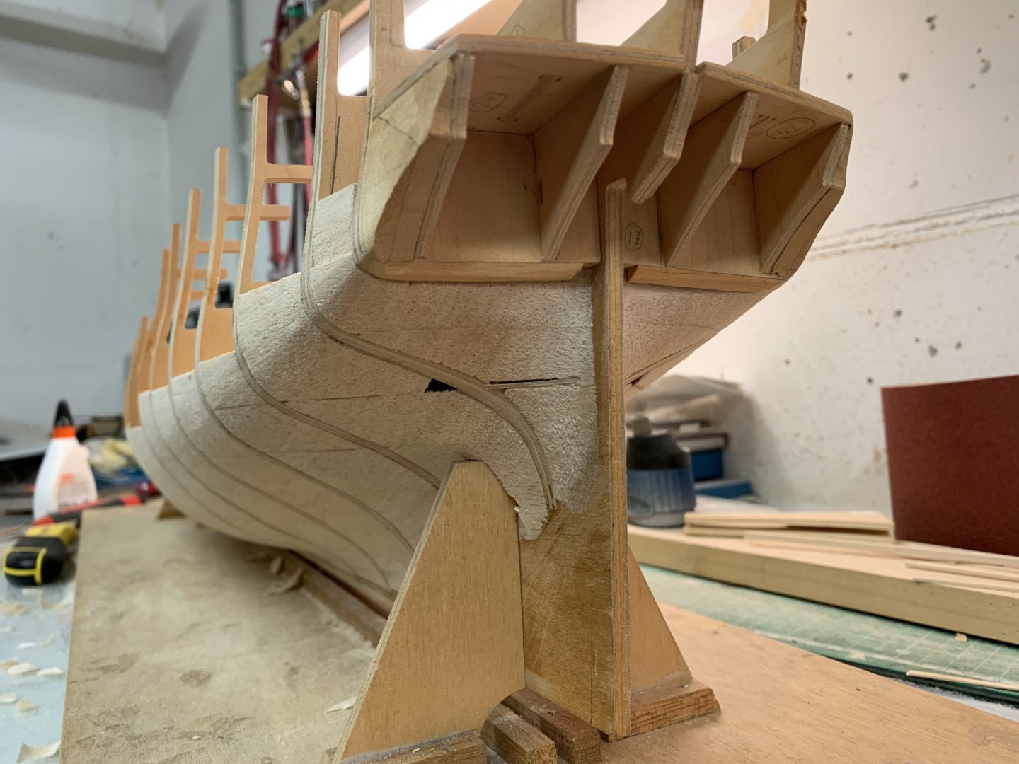
Some glamour shots at the end of the day

that‘s all for now. Thanks for looking,
Chris
- jwvolz, GrandpaPhil, ccoyle and 5 others
-
8
-
Test post to show that I‘m working on my HMS Diana again, after five years! It‘s scary how time flies. I just want to check how uploading images from my phone works. A detailed update will follow over the weekend.

- GrandpaPhil, Barbossa, BenD and 1 other
-
4
-
Yes. there were a few, so I decided to check them first, before the whole thing is glued up. I called the National Maritime Museum to order copies of their historic Diana plans, but they couldn't find them. The lady on the phone thinks they may have gone lost. I'll check again tomorrow or on Monday, see if they have turned up.
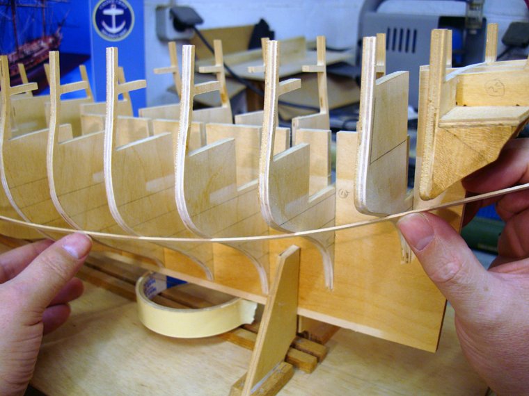
But I didn't want to wait weeks before they do and my oder arrives here, so I decided to move on with what I've got. I went about it the same way as on the other bulkheads and found that the remaining five are closer to the plans than the others.
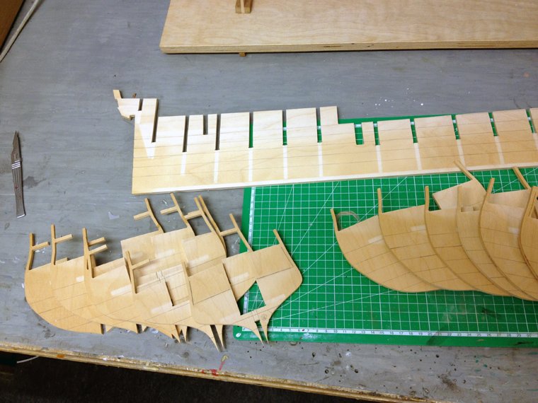
Here they have been trimmed accordingly
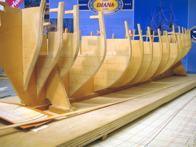
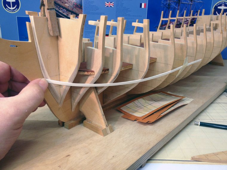
and, again, after bevelling, the test fit strips
Looks like I may have trimmed off too much at the very bottom of bulkheads 8; 9 and 10. This will be corrected with the balsa infills later. A large box with several planks of 15mm balsa arrived at the office today. Excellent timing!
Nothing beats a nice good night photo at the end of your successful building session
--Chris
-
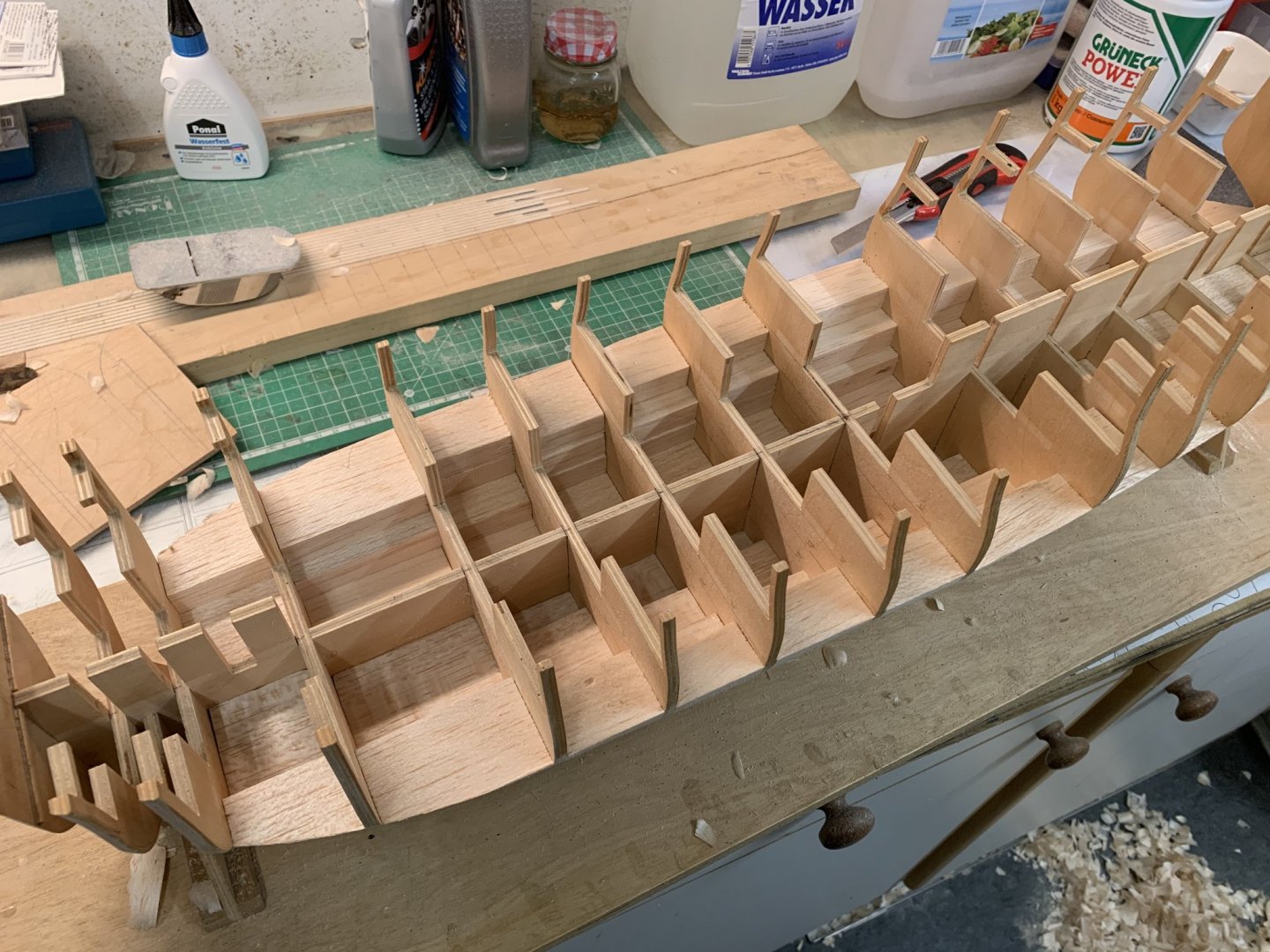
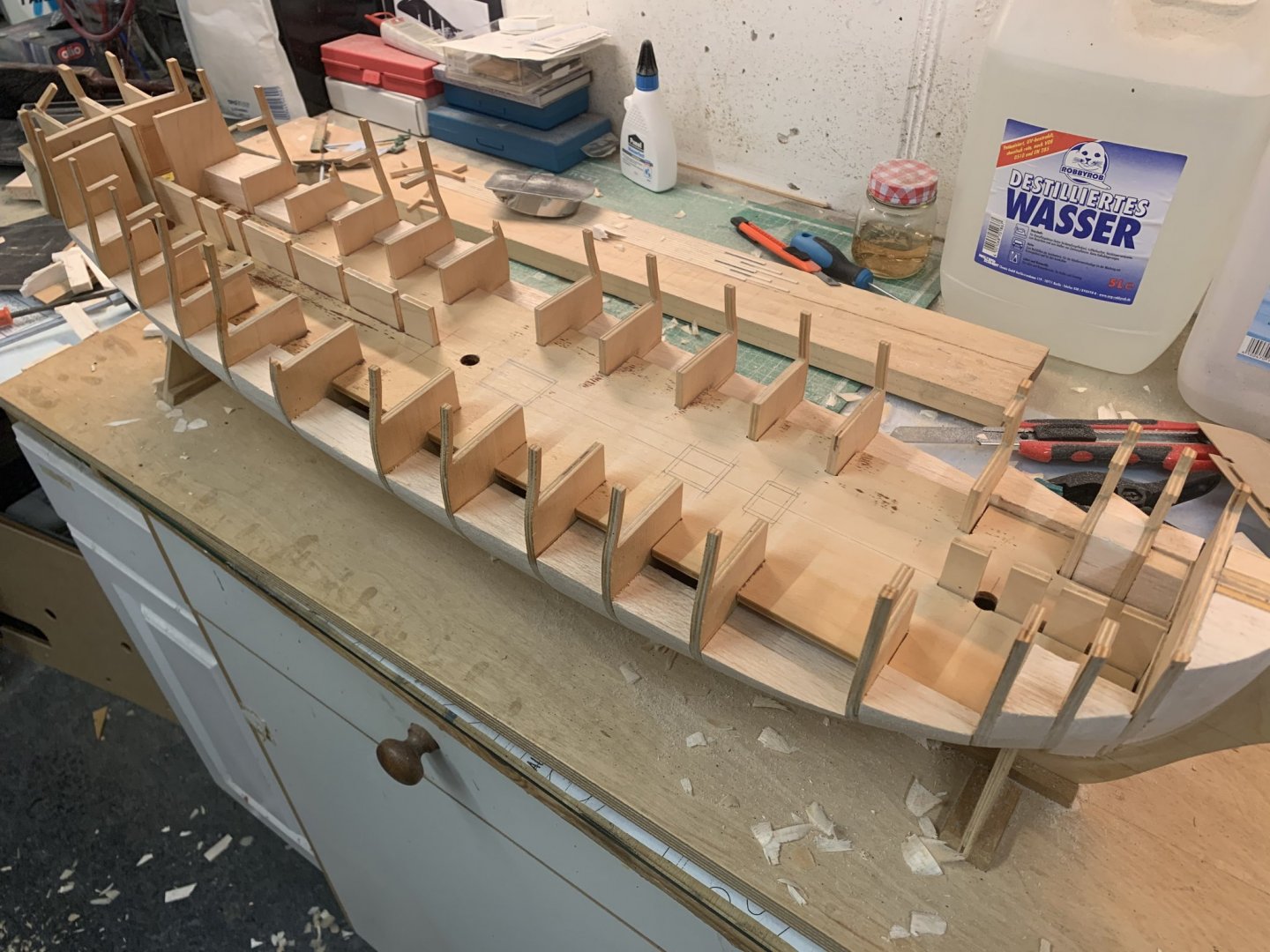
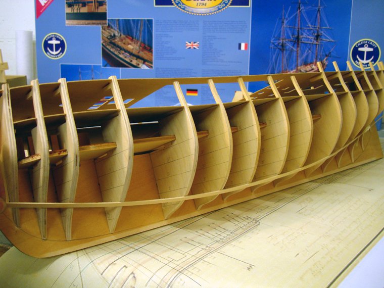
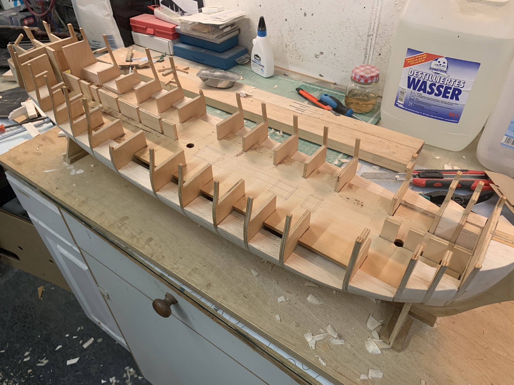
So, the modified rear bulkheads have also been cleaned and bevelled.
I have now completely reworked the rear six bulkheads (except #16 and not counting 17) and have carefully bevelled the front four. That leaves five in the middle. I'm thinking of ordering a set of Diana plans from the NMM so that I can check those remaining five as well. It seems wrong after going through so much work on these 11 and not do the same for the rest. So far everything has turned out quite well.
--Chris
-
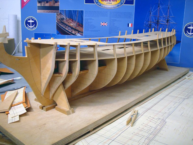
Well it's done now

drove to my brother's house tonight (as we do every Sunday night, to have supper together with the whole family - a nice family tradition)
My brother had balls enough to tackle the bulkheads with his bandsaw.
I'll start cleaning up the cuts and the bevels tomorrow - it's too late here now. I like how they look, though.
--Chris
- DmitriyMarkov, GuntherMT, Ray and 3 others
-
6
-
I'm pretty confident the bulkheads were aligned correctly when I compared them with the plans. The waterlines were the references I used for aligning.
To put this more into perspective I drew on the bulkheads where the curvatures should be according to the plans. Bulkhead #14 would need to have the most shaved off.
Looking forard to this evening, Bro' Let's see what we come up with

-
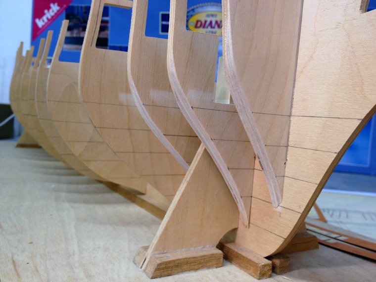
Well after being warned by both of you, I thought I'd give the stern a little more forethought than usual, before bevelling and I promptly ran into a dilemma.
It was quite obvious when even looking at the bulkheads that something was not right. The test strips for planking I use as a guide for bevelling just didn't line up against the bulkheads very well at all.
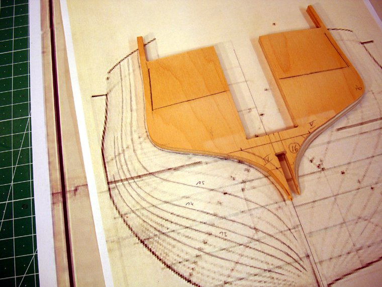
With the plans I had right-clicked from the internet I decided to check each bulkhead working from the back towards the front before I started sanding
16 looked ok...[ish]...
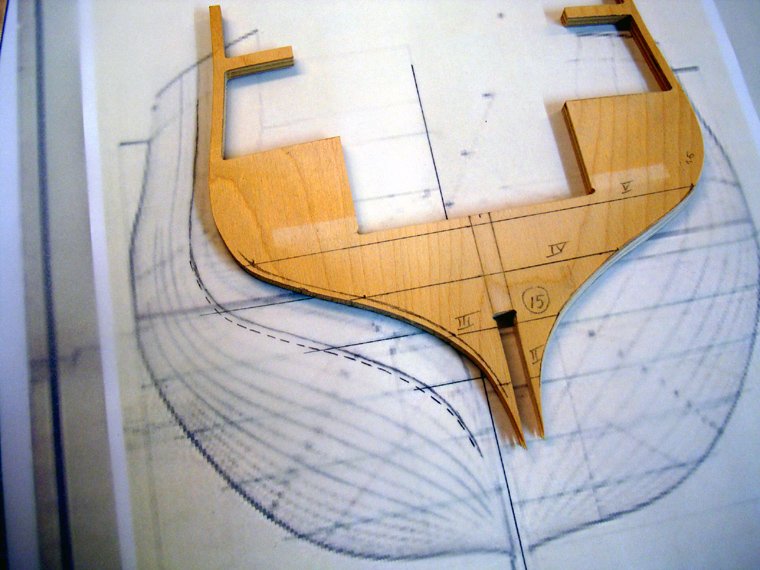
while 15 would also have been passable, but from there it just went from bad to worse (the dotted line is the kits part), here's 15
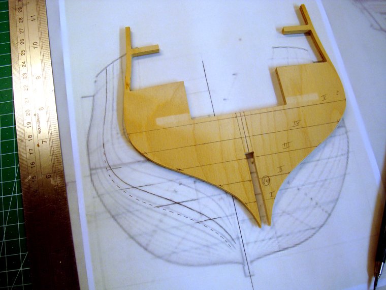
14...
13...
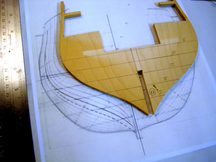
12...
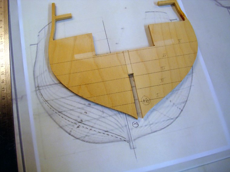
11...
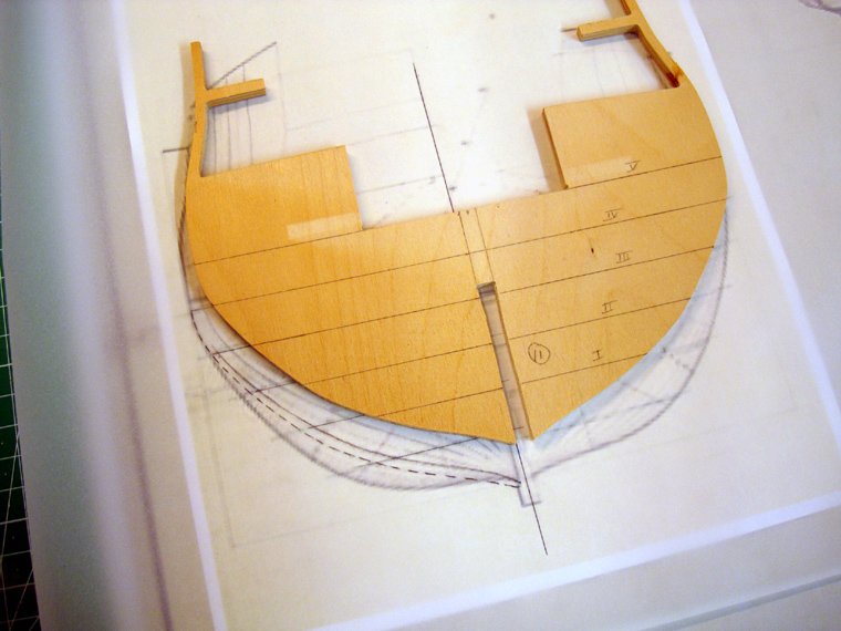
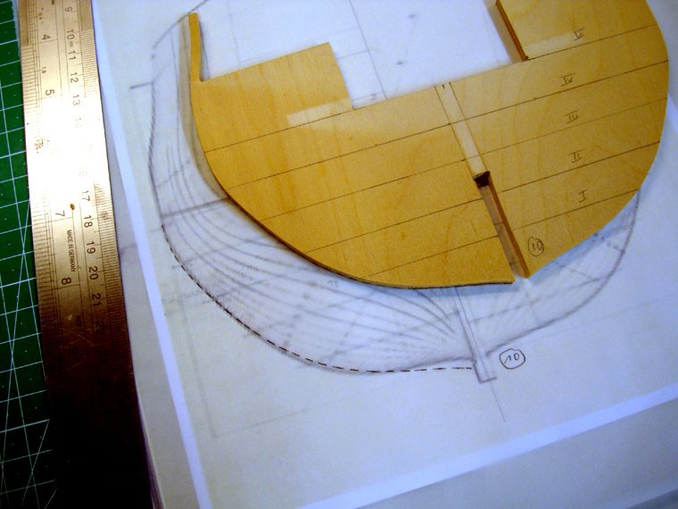
10...
this made me curious so I decided to check them from the bow as well
2...
3...
4...
and 5
Conclusion: if the plans I am using here are really the Diana (and I believe they are, although I have no firm evidence), then the rear bulkheads are quite a bit out of shape. The front ones are very close to to my plans. Close enough to pass anyway.
That is even apparent when looking at them stacked like here
I don't have the AOTS here yet, as it hasn't arrived in the mail. I'm wondering if someone here could scan the drawing with the frames for me, so that I could check the bulkheads with it as an alternative source.
I'm thinking of making scratch built formers for the stern here, just to see how they work out, before I start cutting around on the kit's parts
--Chris
-
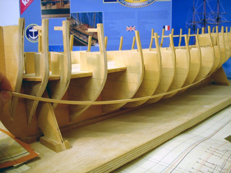
I did a bit more tonight.
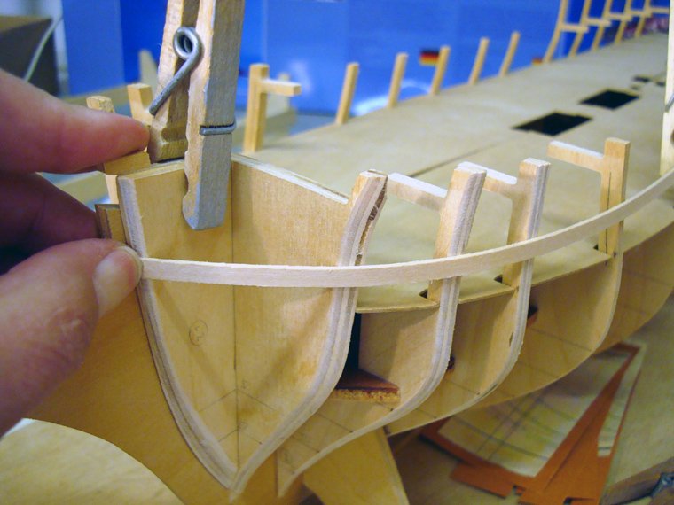
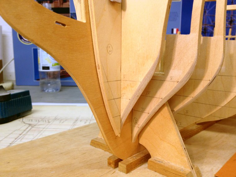
The plank termination templates needing some more sanding, as became evident when testing the plank strips on the bevelled bulkheads. The front edges are now quite pointy.
Then I added some more waterlines to the front bulkhead to help transfer the bevelled edge over to the opposite side. The small pencil mark will act as a guide on how much material needs to be removed to make an exact copy of the bevelled side (hopefully)
Both side of bulkhead 2 have been bevelled here

and here all four front bulkheads have now been completely bevelled. I also tested strip planking here as well and still had to remove some material, before I was completely satisfied. I don't know how many times I took the whole thing apart and built it all back together again to check how the planking will fit.
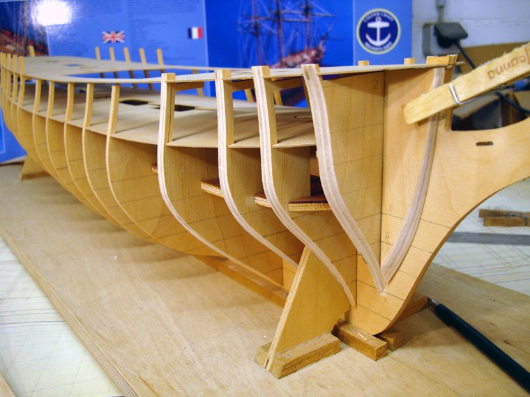
So the first part of step one of the instructions has now been completed. Next I'll tackle the rear four bulkheads. There are some really steep angles on those bevels there!
I'd hate to have to do this on a glued up frame with everything else in the way. Damage would be inevitable.
--Chris
-
Looks like it's an incredible kit. Also, the instructions look amazing. Nice build, of course
--Chris
-
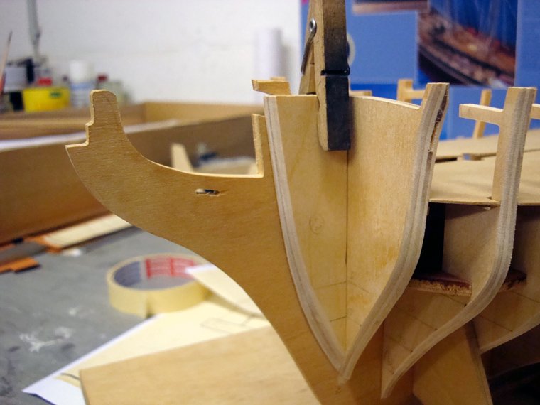
Hi Ray, you are of course absolutely right about the upper parts of the bulkheads. I wasn't really sure when and how to tackle these but tonight I thought I'd just go for it. The waterlines on the plans I found only go up as high as -well- the waterline. Initially I thought I'd wait until the AOAS arrives, hoping there might be some further drawings there I could use to make some more templates, but I gave some careful eyeballing a try this evening, with quite pleasing results. It probably took the best of two hours to do one side (pt) of bulkheads 2; 3 and 4 but by working very carefully and double checking and checking things again it all went well. The distance between the waterlines on my plans is close to 15mm, so I'll be ordering some 15mm balsa to fill in the space between the bulkheads as Ray recommended. Not that it's necessary to stick to the waterlines with the balsa infills, I'm just hoping that it might work out to be a bit cleaner that way and therefore maybe easier. Note how there's a gap in the plywood of bulkhead 2.
I also dug out my old camera tonight as I wasn't too pleased with the quality of the images my i-phone took. This one looks a little bit better.
Thanks for stopping by, and thanks to the mods for fixing my title again (1:64th scale),
--Chris
-
-
Hi Chris, I'm also a Chris, and was also diagnosed with a partial colour blindness which put and end to my ambitions to become an RAF pilot. Ended up in architecure.
Can't wait to see pictures of your Victory (I actually saw -and walked on- the real thing just after christmas)
--Chris
-
Disclaimer (I wonder if this is necessary)
The drawings I printed out from the internet here are strictly for my own use on the model here. No copyright violation is intended. When I am finished using these drawings for this model they will be destroyed. No copies will be made.
Now I've seen I've forgotten to include my name in the title here. How do I work that out?
--Chris
-
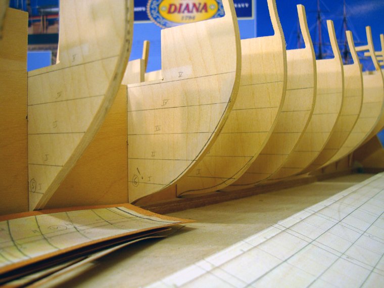
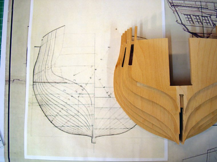
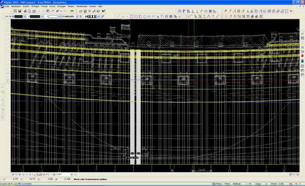
I googled around a bit and found a low res side elevation which I was able to print out in the correct scale (which made it even more low res).
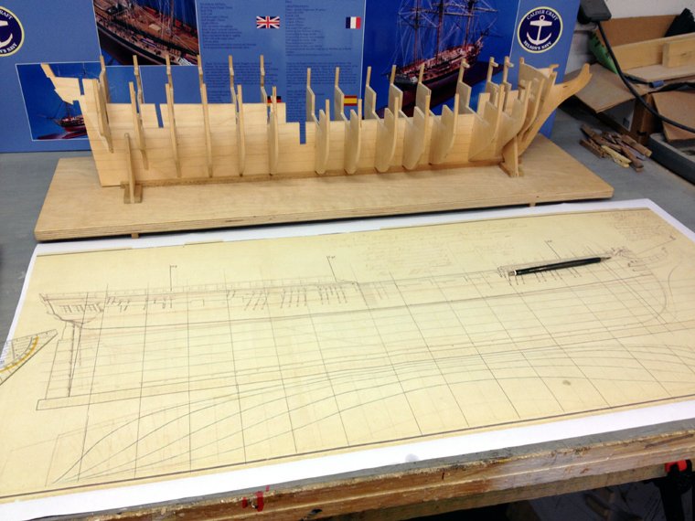
Then I drew out all bulkhead positions on the elevation and lines plan. I'll explain why later.
The bulkheads match the frames on the body plan quite nicely
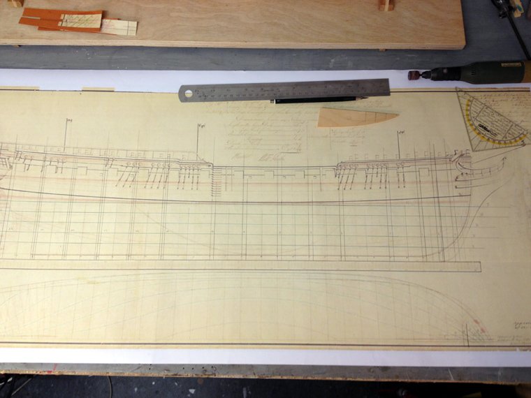
The water lines were then drawn onto the keel and all bulkheads
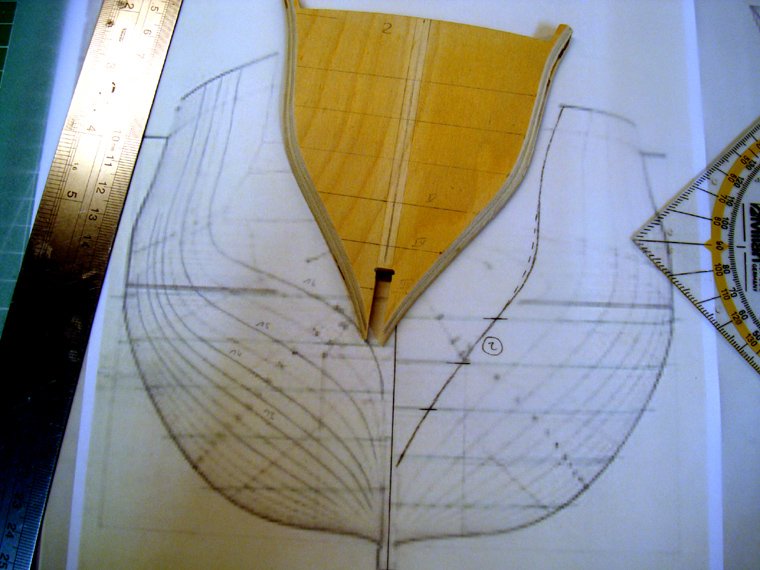
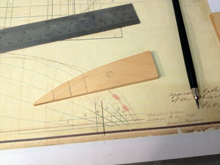
I made templates for each bulkhead from the lines plan showing the angles water lines.
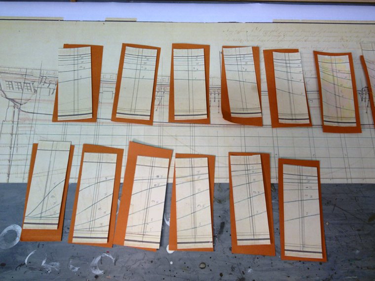
With these angles I could approximately measure out how much needed to be sanded off the bulkheads for the bevels. I'm following the recommendations in the instructions here that the front four and rear four bulkheads should be bevelled before they are glued to the keel. Now you can see why I copied everything onto the drawing I found on the internet.
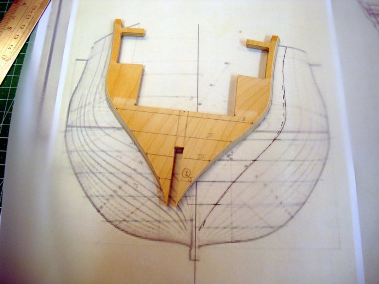
First bit of bevelling done (phew!)

The nice thing about these templates is they can be used to check the angle of the bevels. I watched my brother do this on his dutch Zweidecker

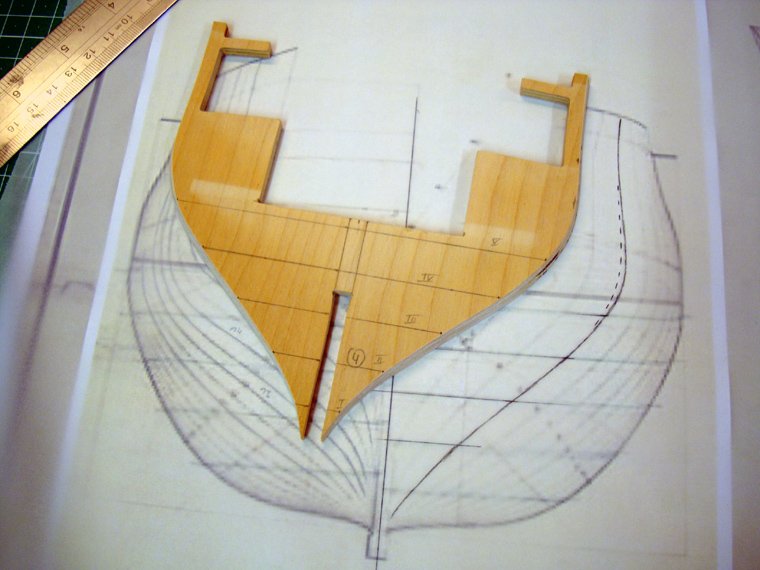
more done
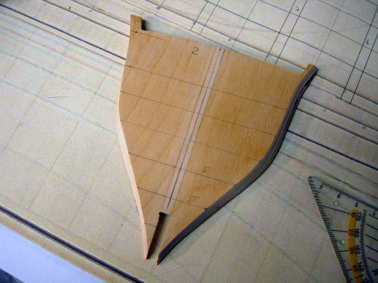
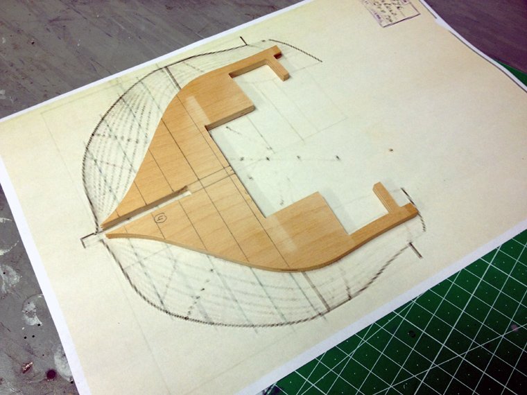
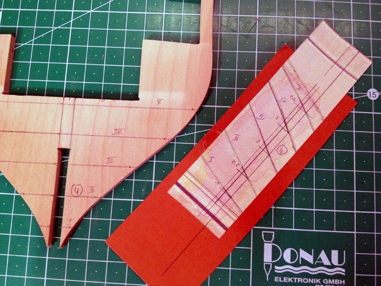
The plank termination template wasn't so easy. I was able to draw out some basic geometry using the lines plan which was then drawn onto the part
quick check in situ
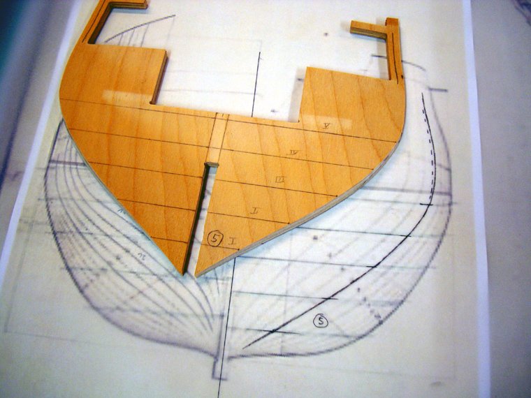
and after about half an hour of careful sanding

I used a piece of plastic card to check that the bevels run true.
So far I am very satisfied. The front four bulkheads are all done. For my next update I'll do the rear four.
--Chris
- Landlubber Mike, Barbossa, GuntherMT and 1 other
-
4
-
Hello All,
after looking around for a while for a nice model ship project, I was able to buy a started Calder Craft HMS Diana in good condition at a reasonable price. I have been thinking of building a ship model for a little while now, and even started designing a few projects for a scratch build, but in the end I decided I needed to get a good quality kit as a first build. The Diana was on the top of my list because a) it's Royal Navy (British ships interest me most) and
 it's a late frigate, a type I find very attractive. So it was pure luck that one popped up on Ebay which turned out to be within driving distance so on a nice Saturday morning I made the trip and bought it on the spot.
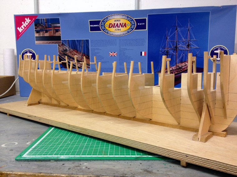
Here she is. The building board was already built by the PO (previous owner). Nothing has been glued yet.
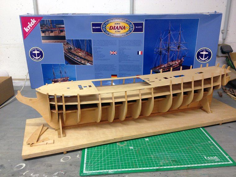
The box top is different than the ones being built here on the forum. Maybe this is an early version kit or one specifically for the european market?
The lower deck had already been painted by the PO. I won't worry about this as I want to plank the deck anyway and maybe add some details
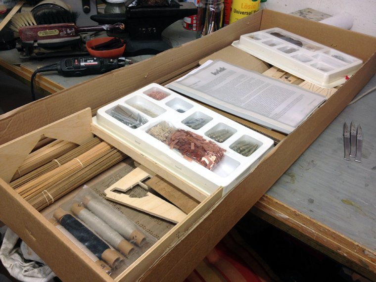
This is what's in the box
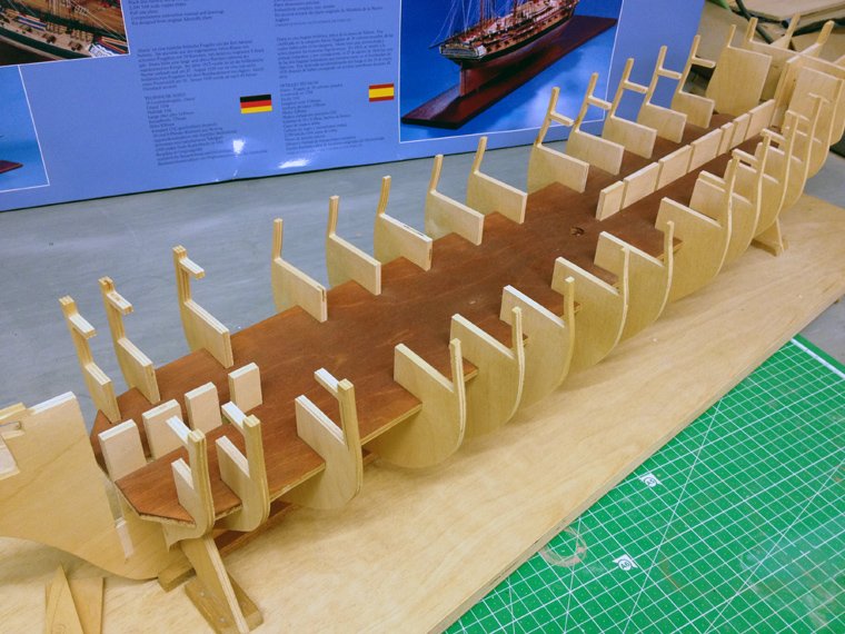
The stern section was also already built. All to a good standard.
And here another view.
I have already ordered the AOAS on the diana and hope it arrives soon as I intend to dress out the lower deck a bit, even if it's hardly noticable later.
This is my hobby cellar, all cleaned up (happens very rarely!) for the new build
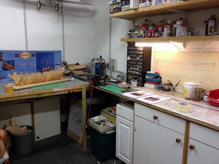
So, this is my first wooden ship build, so please be patient with me. I have always been a slow builder so this might take a few years - haha.
Feel free to tune in, next I'll show you the beginnings of part one: Hull construction.
--Chris
- BenD, mort stoll, GuntherMT and 4 others
-
7
-
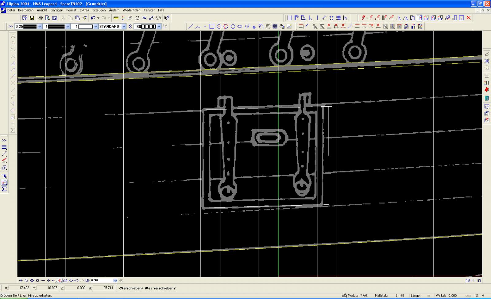
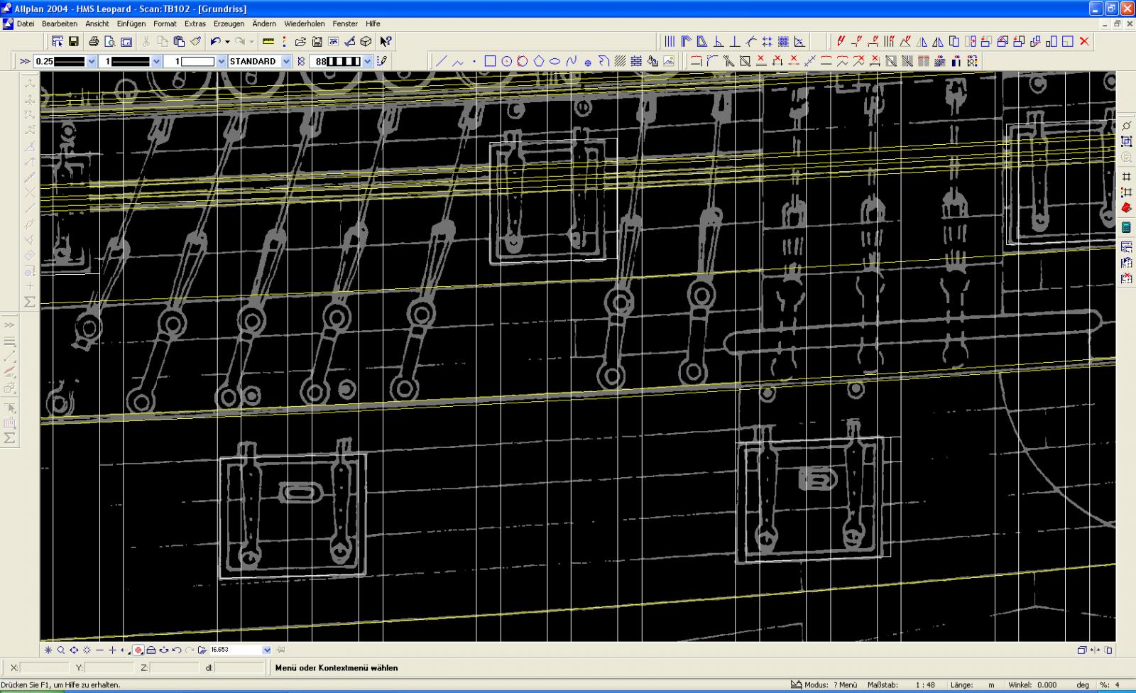
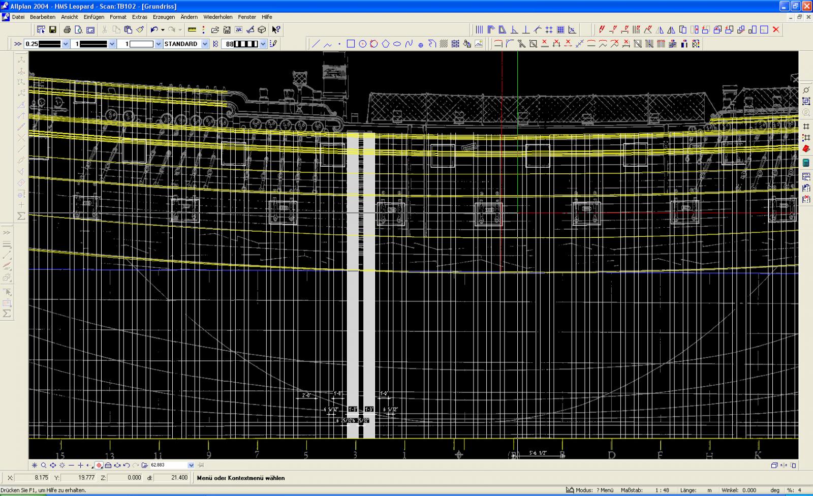
I have a question here about the NMM's Bellona plans that I imported into my CAD programme for an off and on project. On the side elevation I noticed the frames stations are tilted very slightly to the rear. I have the elevation placed in my CAD programme with the water lines absolutely horizontal, which makes sense to me. The scale bar under the keel rises towards the bow which also looks right. So I was wondering if the rear tilted frames might be due to the photographic process in the museum or even scanning them here afterwards (or a combination of both).
This is an amazing thread and one of my favorites on MSW. I come back here frequently to see Marks progress and follow the discussions.
Chris
-
Question here for Chris Watton. This was originally posted at AEW's Vanguard build but he recommended asking Chris here as well. The Vanguard being an Arrogant-Class design is very similar to the Bellona-Class, if not even a direct copy. Would it be possible to convert the Vanguard kit to a Bellona-Class design? I know there are differences in the decorations, but I'm hoping the rest may be pretty much the same. I think I read somewhere that there were a few changes around the bow only, but I could be wrong. If Chris could enlighten me, that would be very nice.
I would also like to say that this thread is the one I check out most frequently, to see Chris' progress on his Victory and to find news on a pending Victory Models Bellona kit. That Bellona in the picture on the first post here of Chris' Bellona is one of the most beautiful models I have ever seen. Chris (another one)
-
Now it's where it should be. Thanks for stopping by. Please provide as much input as you can. So far this has been quite enjoyable, but as I've said, I have a lot to learn. Next I want to work on McKay's Body Plan. Maybe with some help from Avery I can draft my own frames. We'll see.
--chris
-
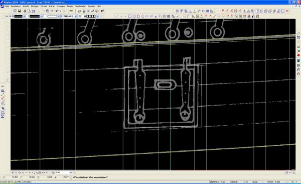
The top centre gun port here is not located exactly between the two single thickness frames here (you have to look closely and you'll see what I mean). I changed its position. Actually I went through all gun ports and moved them around just a tad to put them right where I think they need to be. This was the first deviation from McKay's Profile. Would you have done the same? I'm assuming this is a typical inaccuracy you would find on ink drawings.
-
-
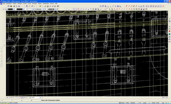
There was a slight difference of frame thicknesses about where the steps are on the hull, just aft of the dead flat. I solved this my own way by omitting the double thickness frames here next to the gun ports and increasing the single frames to 1' 3". This turned out to be a very tidy solution and I was very pleased about that. I have not made a decision yet on what scale my project will eventually be. At the moment I am designing my Leopard full size, which is one of the advantages using CAD programmes. I did print out a side view, sorry, the Outboard Profile in 1/36th and 1/48th scale, but, boy, those scales would make a BIG model. For now I'm comfortable working full size.


HMS Diana 1794 by CTDavies - Caldercraft - 1:64th Scale - as built - first wooden ship build
in - Kit build logs for subjects built from 1751 - 1800
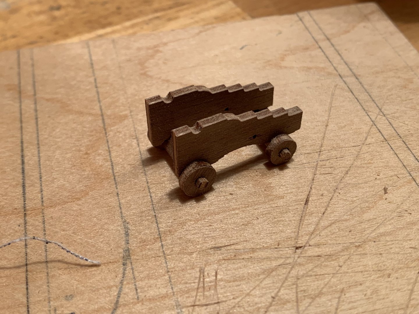
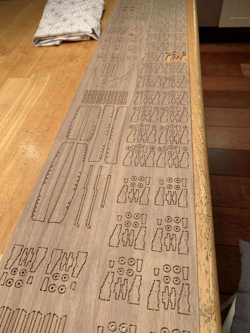
Posted
So after several hours I had cut out all the parts for the carriages. Not only did the tabs need removing, but there was a load of milling debris stuck to the edges which also took a while to clean up. I was about halfway through this all when I noticed that the cannons (and the carriages of course) were in two different sizes. So I spent an extra few hours sorting everything out again.