Javelin
-
Posts
316 -
Joined
-
Last visited
Content Type
Profiles
Forums
Gallery
Events
Everything posted by Javelin
-
 hmm, kind of makes me think: Just kidding, great paint job and thanks for explaining your technique.
- 493 replies
-
- 7
-

-

-
- vanguard models
- alert
- (and 1 more)
-
Of course I'm in too. One question though, are you going to have the water level (and ship) in the bottle level with the bottle side, or angled with the bottle and level with the sea surface underneath?
- 290 replies
-
- 4
-
-
- Quinquereme
- Finished
- (and 1 more)
-
They started using spherical trigonometry or spherical goniometry. It's a very different beasty from planar trigonometry. Distances between two points a sphere's surface are measured in angles. They can later on be converted to distances, depending on which sphere you use. Practically this is still the way we navigate today, except of course that a lot of it is automated. Not sure who or to what degree they used it back then. Gorgeous build by the way! Been following along for a while now.
-
They're called sea anchors and are commonly used on lifeboats, so nothing new... Using them for such a ship on the other hand. Gorgeous build Rob, love what you did with that sea base.
-
Spartacus by Javelin - 1/2000
Javelin replied to Javelin's topic in - Build logs for subjects built 1901 - Present Day
That depends. Preferably a floating pipeline is used, this ranges from a few 100m till several miles. Occasionally, when distances get long and traffic needs to pass, the floating line is connected ho a sinker line on the bottom, so traffic can pass over it. You do still need a floating line to give flexibility to the dredger. The pipeline is connected to a swiveling connection on the stern of the vessel. Spartacus Stern Connection In cases where this not possible, the dredger can either load barges using 1 or 2 barge loading pipes, T shaped on PS on Spartacus, or pump it in trailing suction hopper dredgers using the stern connection and a pontoon. On Spartacus, the pipes are 1.2m diameter and she can pump between 14 and 19km depending on material density and pipeline diameter. I still need to build the barge loading towers, I'll have to hinge the inwards to pass the bottle neck. -
Spartacus by Javelin - 1/2000
Javelin replied to Javelin's topic in - Build logs for subjects built 1901 - Present Day
Hi Glen, it's a mix of circumstances I guess. I used to sail in the Merchant marine, however those ships (large tankers) aren't very suitable for bottling, you have to reduce the length so much to fit inside a bottle, that you automatically end up with a tiny scale. That in turn makes for a very low height and width of the subject, which means it would simply fit through a bottle neck without any "special" features, they also don't really fill a bottle very well, apart from their length. When I changed career to dredging, I got a wider view on these working vessels with very irregular shapes and dimensions. They're also generally smaller, which allows for larger scales. Although it is forbidden for me to post onboard pics, I guess I can post pics of the vessel itself as practically anybody can see it, and take pictures, this way. The above picture is more or less what I'm aiming at in my bottle. The main difference would be that I want the ladder on the bottom and 1 anchor on the bottom (ladder is up in this picture, you can see it behind/inside the forward dark green platform). Funny you'd ask for the material. It's sheets of styrene/styrol of different thickness glued on top of each other. It's funny because my technique is more or less stolen from you The only difference being the styrene instead of your method using wood. I got inspired for the gallery on this ship, as well as the small rooms aft inside the hull by your work to insert cannons in one of your builds. Currently working on the dredge anchors themselves and then one of the main remaining items is the large travelling gantry crane. The idea is to mount it with two pins to the superstructure, with the crane laying down, in order to be able to rotate it upwards when the vessel is inside the bottle. Haven't really completely thought this one out, but I guess it might work this way. Just need to take into account that the auxiliary spud will also be folded forward. I've also built the gantry version 3, I made it thicker with each consecutive version to attain proper angles on the small wings on the sides.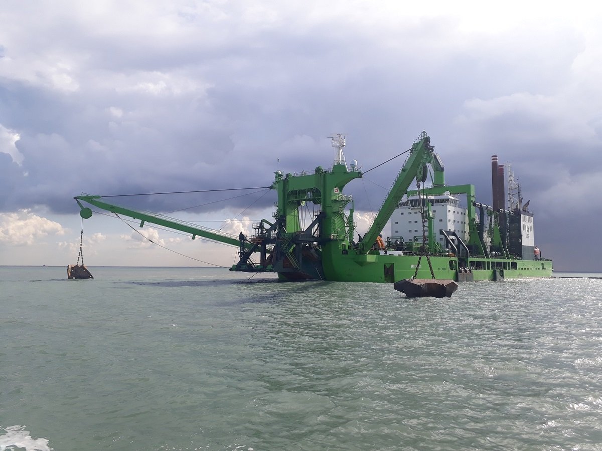
-
Spartacus by Javelin - 1/2000
Javelin replied to Javelin's topic in - Build logs for subjects built 1901 - Present Day
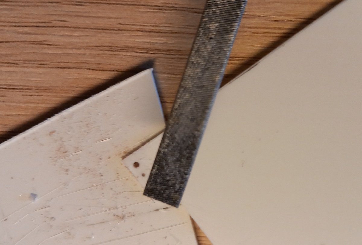
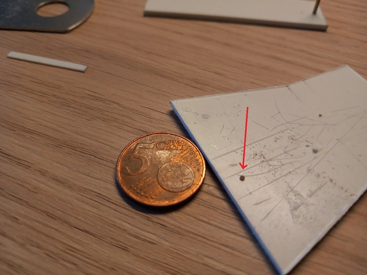
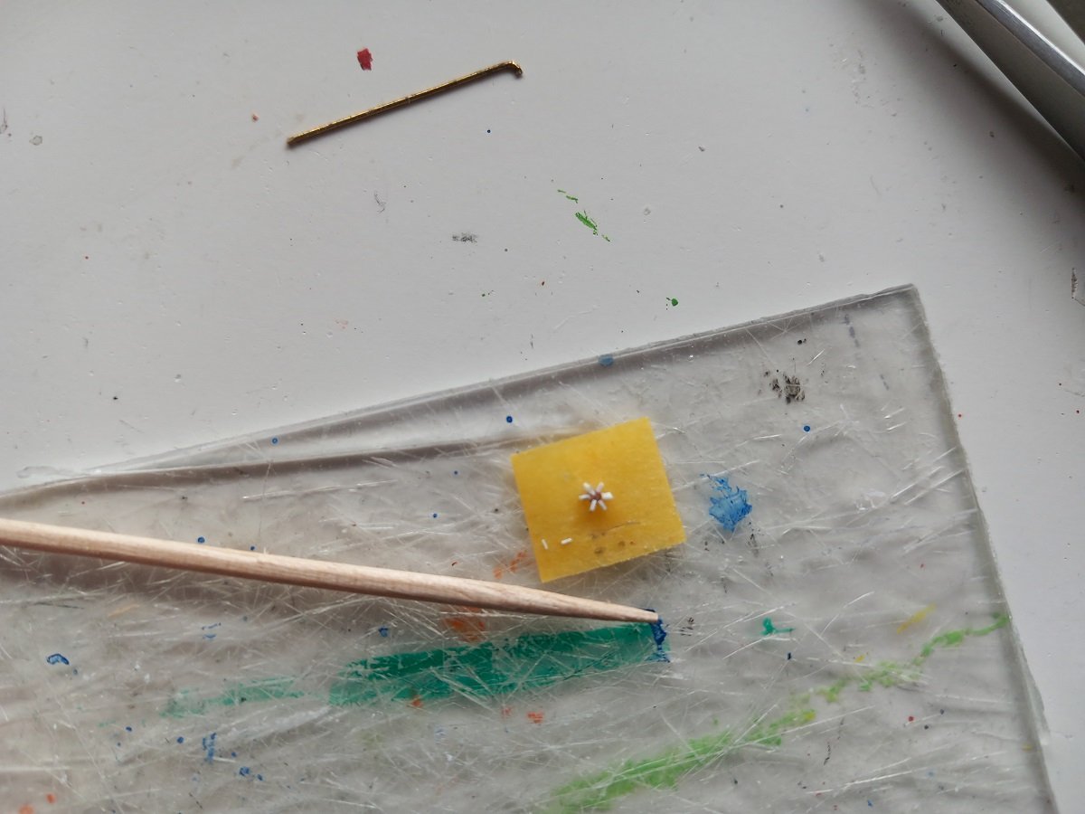
Not much progress to report. I've been mainly building 20 20ft containers, of which I'll probably use around 15 or so. I still need to make some half-height containers and probably a tank-container which is also frequently used on this vessel. Furthermore I've finished some of the main winches (Anchor Hoisting Winches and Guy winches, the latter of which are used to move the anchor boom in/out). Remaining are the largest, the Side Winches, the ones that pull on the anchors to move the ladder and vessel back and forth. For today's post I decided to share my way of making small sheaves or nice equally sized pieces of wire. I use the same way to make the end of a rod flat, which is a difficult thing to make nicely at a 90° angle. For large diameter discs, I use a normal leather punch for making holes in belts. However for small things, like 0.5mm, 0.8mm or 10mm pieces or sheaves, I use following method. Drill a hole in a piece of styrene with the same thickness as the length you require. In the example below, I wanted a 1mm-diameter disc with a thickness of 0.5mm. So I drilled a 1mm hole in a 0.5mm thick piece of styrene. Then you insert the rod and just let it protrude. Later on, I put it on a flat surface and cut it off using the sheet as a knife guide. Then, while pushing the styrene down on a flat surface (steel ruler) I file along the sheet until the rod is flat with the sheet edge. I then punch it out using a piece of wire. If you want them thinner (in this case I went to 0.3mm thickness) I insert my small disc into a 1mm hole in a 0.3mm thick piece of styrene and I repeat the same process. In this way I ended up with 4 identical 1mm discs for use on the vessel. When making a flat surface at 90° on a rod, I use the same method, except that I don't cut off the rod. I simply let it protrude along a piece of styrene and file it flat against the sheet. In that case I often use a 2mm thick piece and pay particular attention to drilling the hole straight. Same works with 0.5 or 0.8mm brass rods.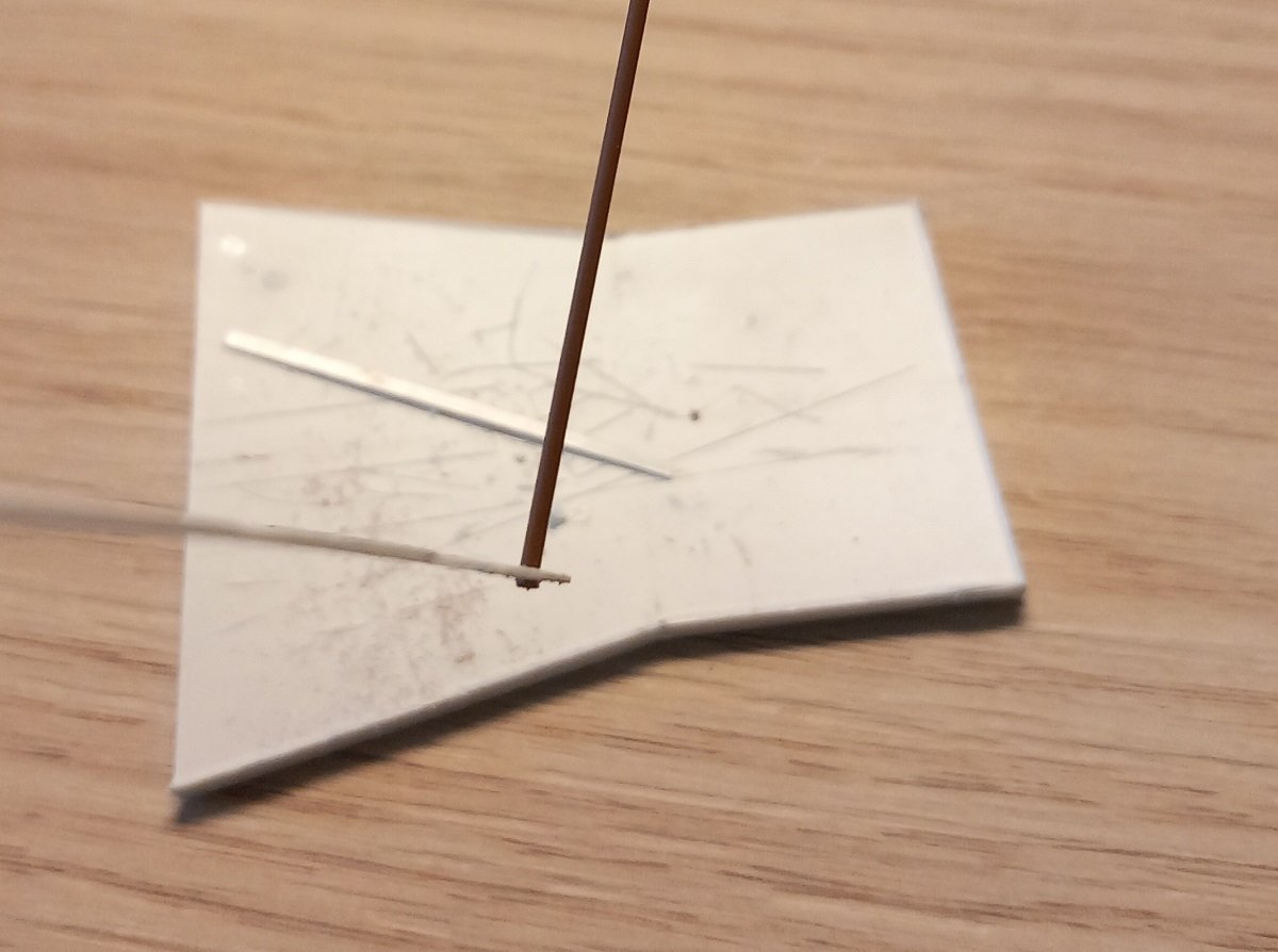
-
Spartacus by Javelin - 1/2000
Javelin replied to Javelin's topic in - Build logs for subjects built 1901 - Present Day
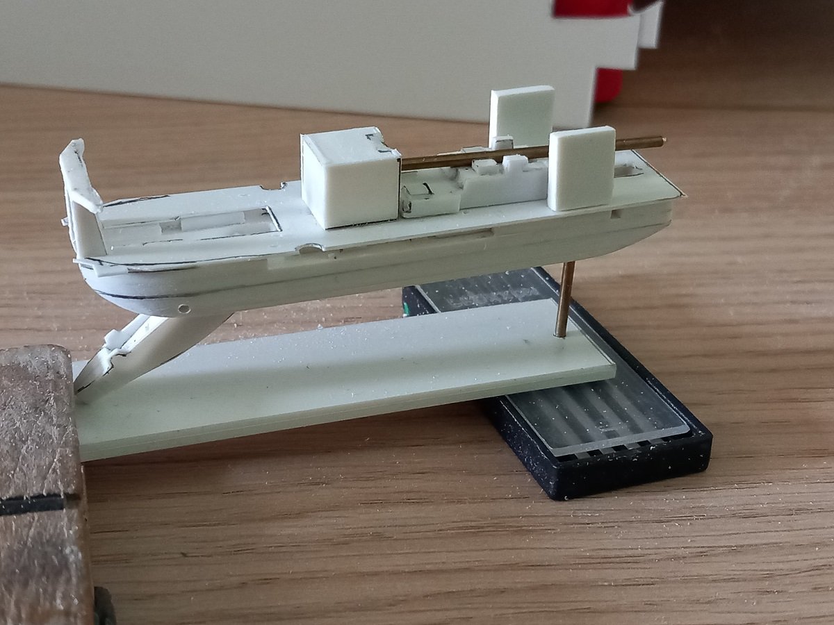
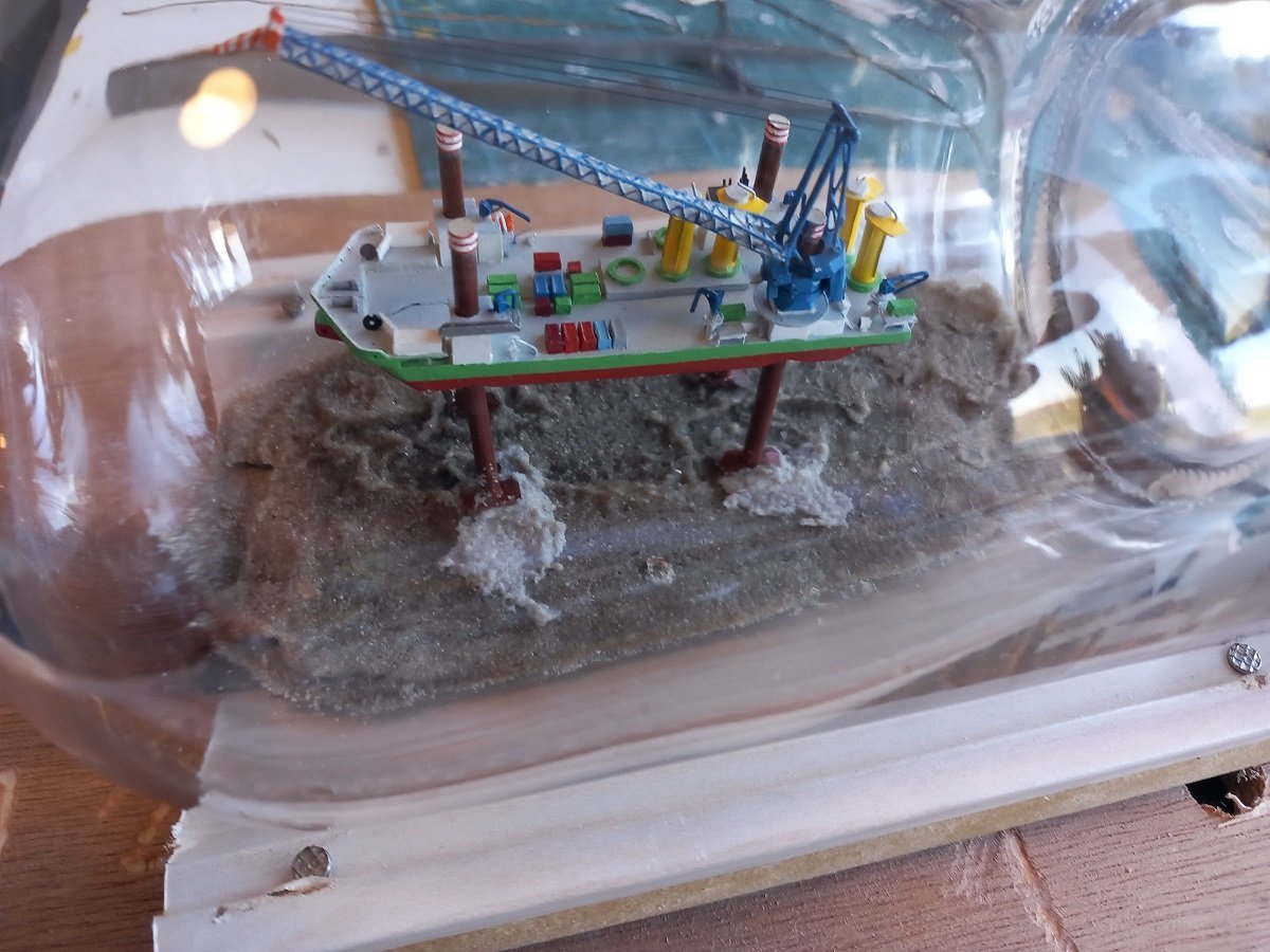
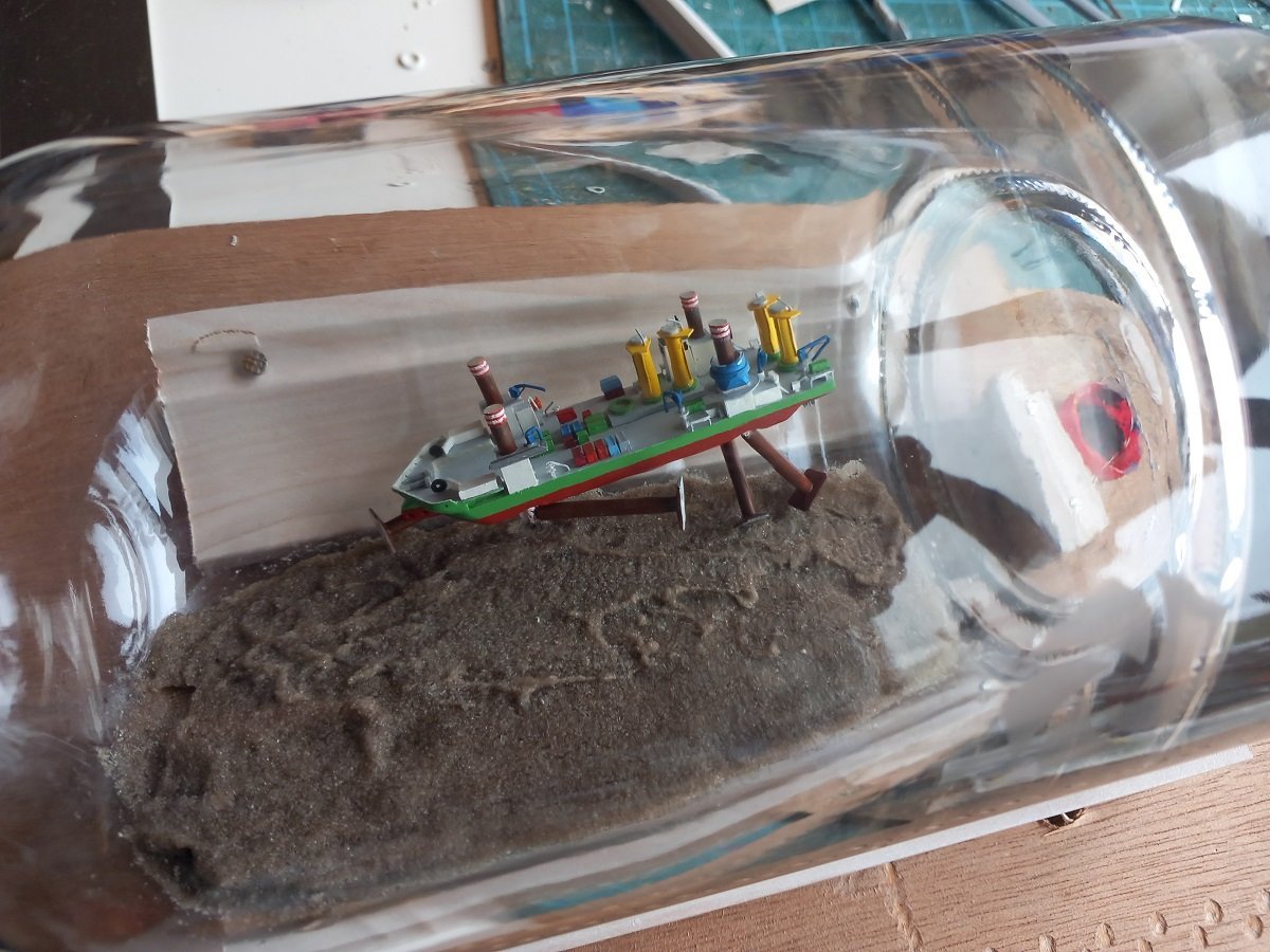
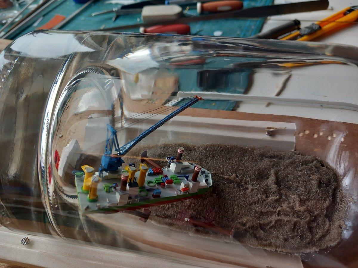
Made some more progress. As mentioned before, I mounted the crane deck. All in all I should be ok for the painting, as almost everything below it is very dark green (Moss Green), so painting won't be that delicate. In the meanwhile I've mounted the anchor booms. Small idea of what they're used for. As I've mentioned in last post, the dredger swings from port to starboard and back around its spud, moving the cutter ladder and the big cutter. These swings are done by pulling and veering (big) anchors. in Spartacus' case, the anchors are 60t Stevshark anchors (which are used to permanently moor offshore vessels as well). These anchors are connected to the ladder through sheaves just behind that cutter. The winches are mounted just in front of the accomodation block. As the dredger moves forward, the angle of the wires between the ladder and the anchors becomes worse, certainly when the dredger is in a corner. The pulling vector to move out of that corner becomes bad as the dredger moves forward of its anchors. At some point the anchors have to be moved forward, along with the dredger. At that point the anchor boom is swung out, while at the same time pulling in the neuring wire (to pull the anchor out of the bottom). Once in the corner, the anchor is pulled up, hanging in the anchor boom and the anchor boom is then moved forward. Once in a more forward position, the anchor is lowered again and the wire to the ladder is pulled tight. The boom is swung back in while veering the neuring wire, to lay it on the bottom and out of the way of the cutter. Then the dredger moves back to the other side. The two small 0.3mm steel wires you see represent the gantry crane track. Here they are still dry fitted, but I will glue them early on. This will help me divide the deck in fixed parts and force me to stay to scale with all small structures that come around the tracks. This will avoid cumulative (and very visible) errors later on. In general all large components are now ready (but dry fitted). So I can continue with small components like hatches, deck houses, containers, pipelines etc. to give her her typical cluttered look. The idea is to rig the anchor booms in outward position and then fold them inside, to be deployed again once inside the bottle. I'll probably depict her with one dredge anchor at the waterlevel and 1 on the bottom. A moment when the dredger arrives on a new cut. The challenge will be to make, and keep, the rigging tight.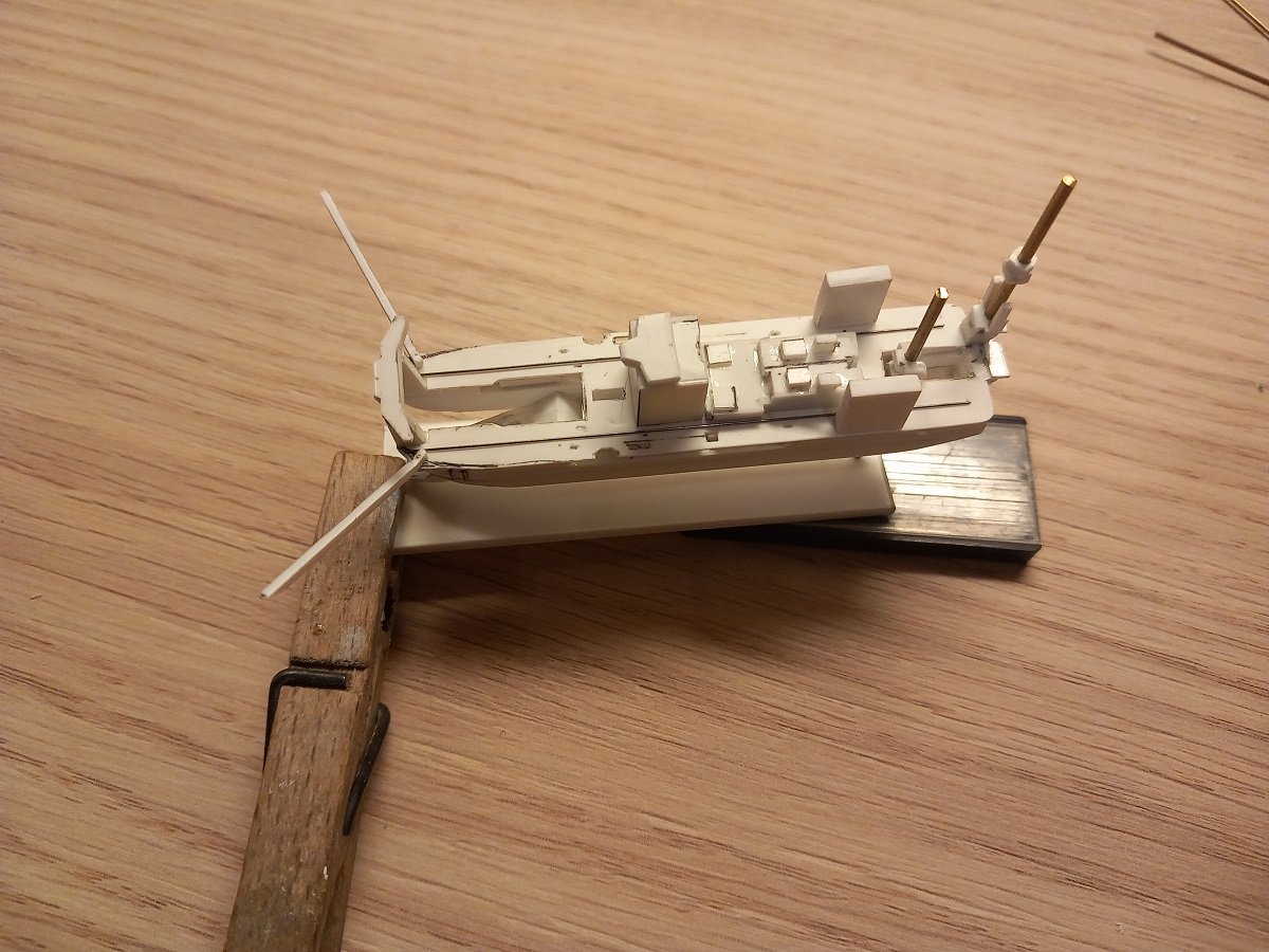
-
Beautiful work on those carriages and barrels. Thanks to you, I now know what a culverin is!
-
Spartacus by Javelin - 1/2000
Javelin replied to Javelin's topic in - Build logs for subjects built 1901 - Present Day
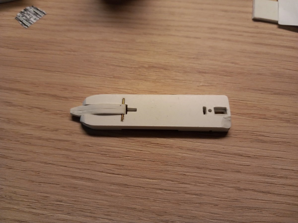
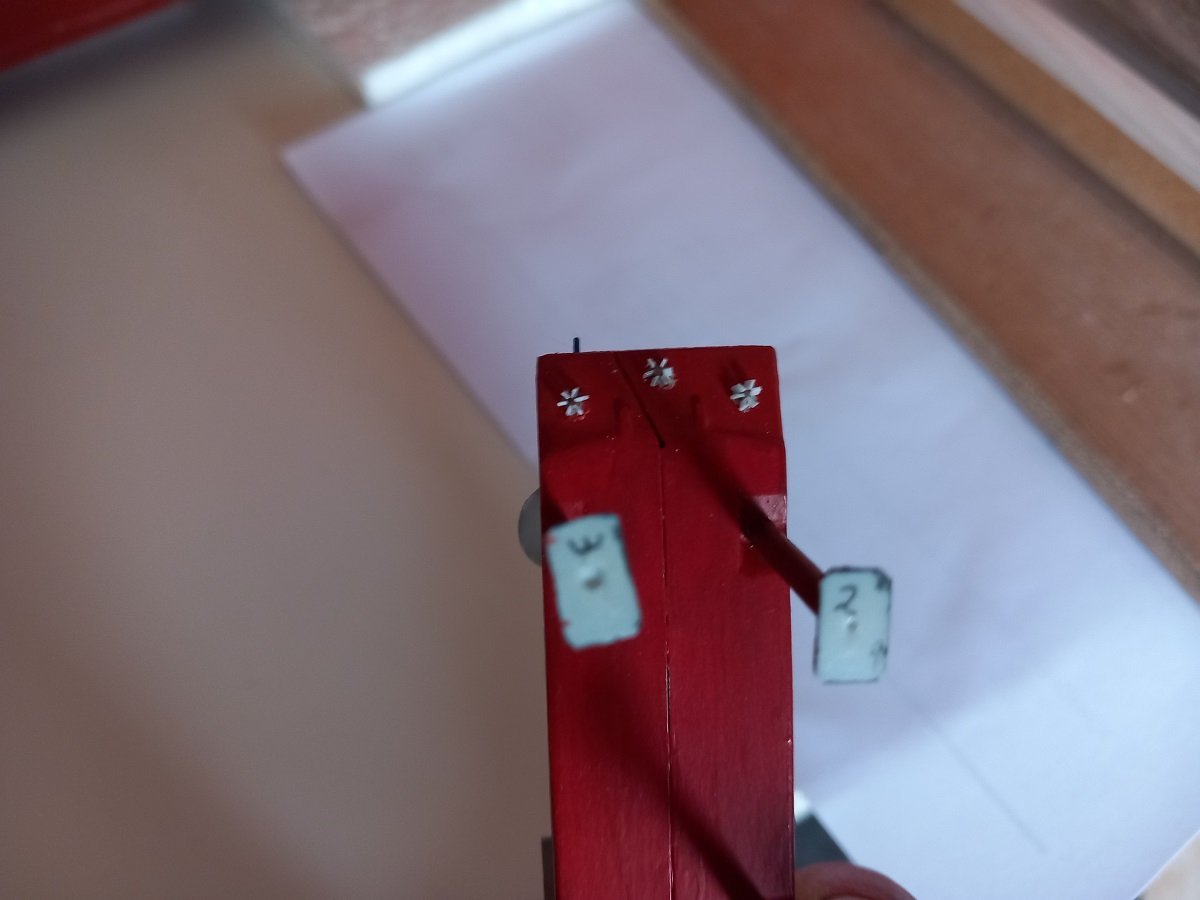
Guess it's time I'd give some more explanation about how this thing is supposed to work. Essentially it all started with the well known bucket dredgers. An evolution of those was to have a rotating cutter head, with the broken soil being pumped away. In the beginning they were small stationary barges, with only their spud poles to keep them in position. When they were finished in one area or when they had to move for traffic, they were being towed, mostly astern, to a new position, where they'd position their central, main spud and deploy the anchors to start working again. At long distances from shore or reclamation areas, they'd use booster pontoons, equipped with 1 or more pumps along the floating line in order to get the soil where it was needed. Slowly the cutter suction dredgers were growing in size, additional pumps were added to the vessel itself. Additionally they'd get barge loading facilities so they could work in areas where pipelines couldn't be used (traffic etc.) or when the soil had to be dumped somewhere far away. Due to this, also the supporting vessel, which was used to deploy anchors, bring logistics, move the vessel and arrange the pipeline, had to grow as well. At some point, it became more practical to give the dredger its own propulsion and make it a real ship. This way it could transfer from one place on the planet to another without being towed or transported on a heavy lift ship. It also gave more freedom to move the dredger, while the supporting vessel could tend to the pipeline. Recently I've been working on the spuds for the tiny model. There are two spuds, 1 is forward and centrally mounted on a carriage that is being pushed forward and backward by a hydraulic piston (in reality, when the spud is in the ground, it's the ship that's being moved forward or backward). The other spud is called the auxiliary spud and this one can only be pulled up and lowered, no longitudinal movement. The vessel moves from portside to starboardside and back while the main spud is in the ground. The spud keeps the ship from being pushed backwards by the force of the cutter. Once the cutter comes in the port or starboard corner, the ship steps forward and then swings back. When in the opposite corner, it steps again forward and swings back, this is done until the spud carrier (hydraulic cylinder) is at the end of its stroke. Then the auxiliary spud is lowered in the ground, the main spud is lifted and the carrier is brought forward again with the spud off the ground. Then the main spud is lowered in the ground again, the auxiliary spud is lifted and the ship starts swinging again. Below you can see the spud on the model. The main spud is made of two parts, the lower part holds the ship up, while the upper part is just part of the model. You can actually see the ship lean back due to the backwards force of the forward support/cutter ladder against the laundry pin. I will however fix that spud upright by adding another layer on the base plate. For the auxiliary spud, I needed a different solution, its supporting structure has a hinge in it, so the spud will be lowered horizontally to pass through the bottle neck. It will almost look realistic as the spuds are both put in a horizontal position when the ship has to sail from one port to another. When it shifts during dredging, both spuds are simply hoisted as high as structurally possible, but they stay upright. This is all still dry fitted. I have in the meanwhile decided that despite the difficulty to work on the lower level afterwards, I will mount the main deck/ crane deck anyway. Otherwise I'd already be stuck. If I do mount that deck, I can continue the construction much longer with my mobile equipment.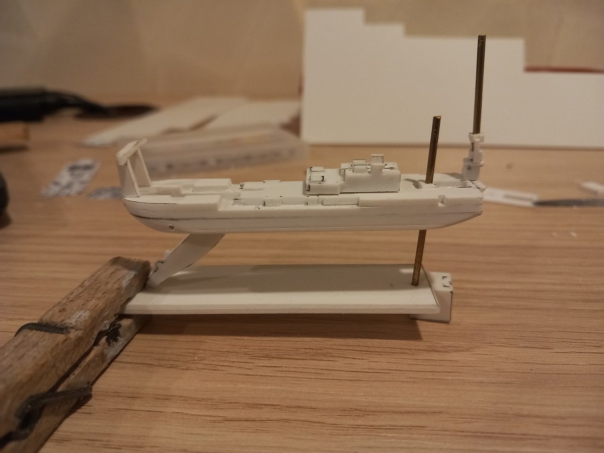
-
Spartacus by Javelin - 1/2000
Javelin replied to Javelin's topic in - Build logs for subjects built 1901 - Present Day
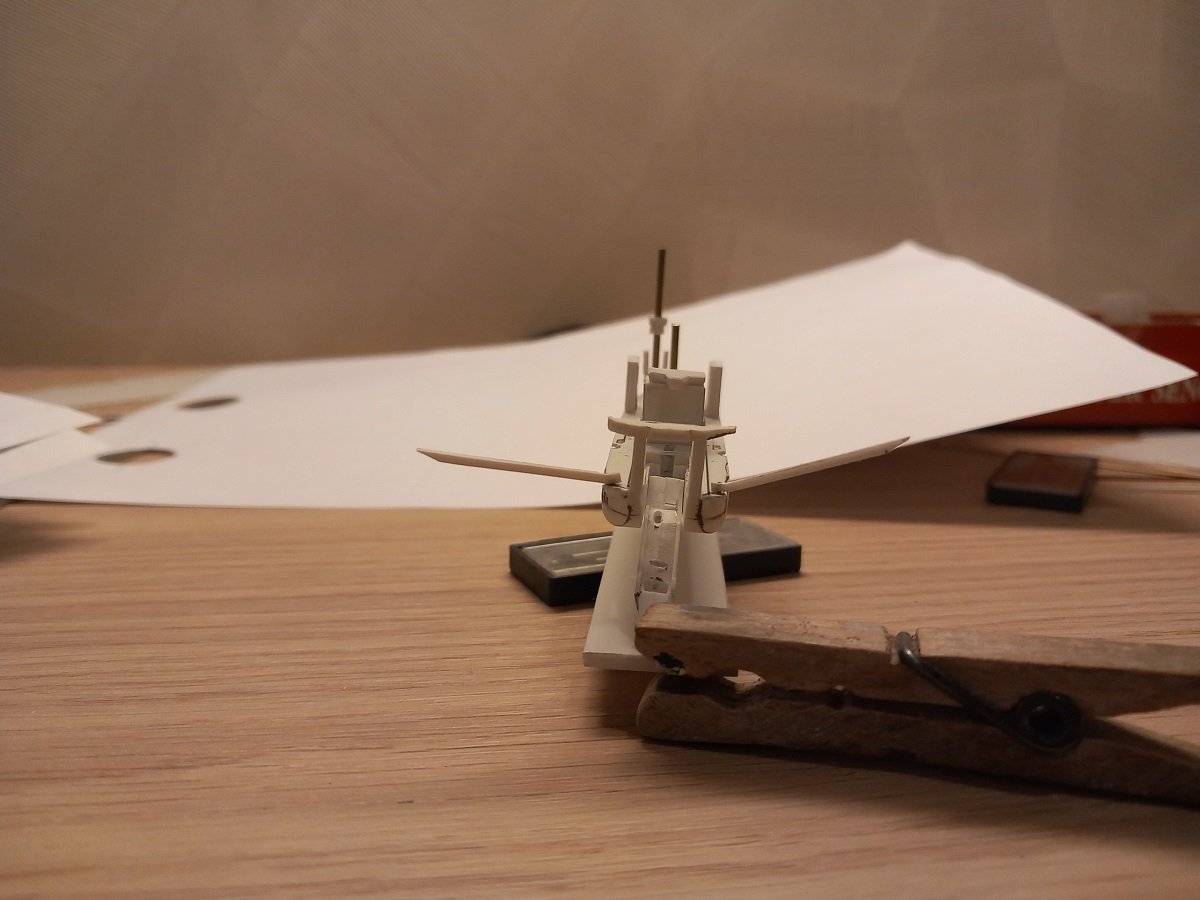
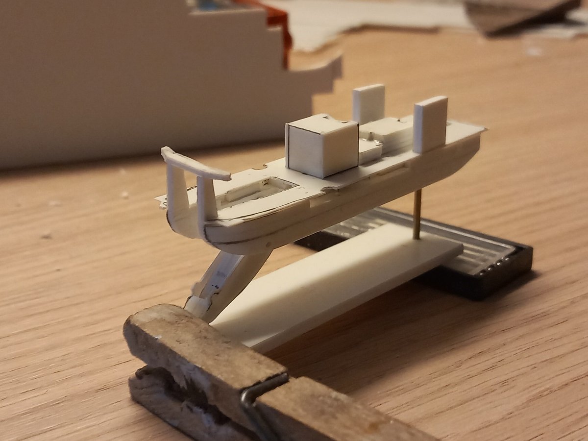
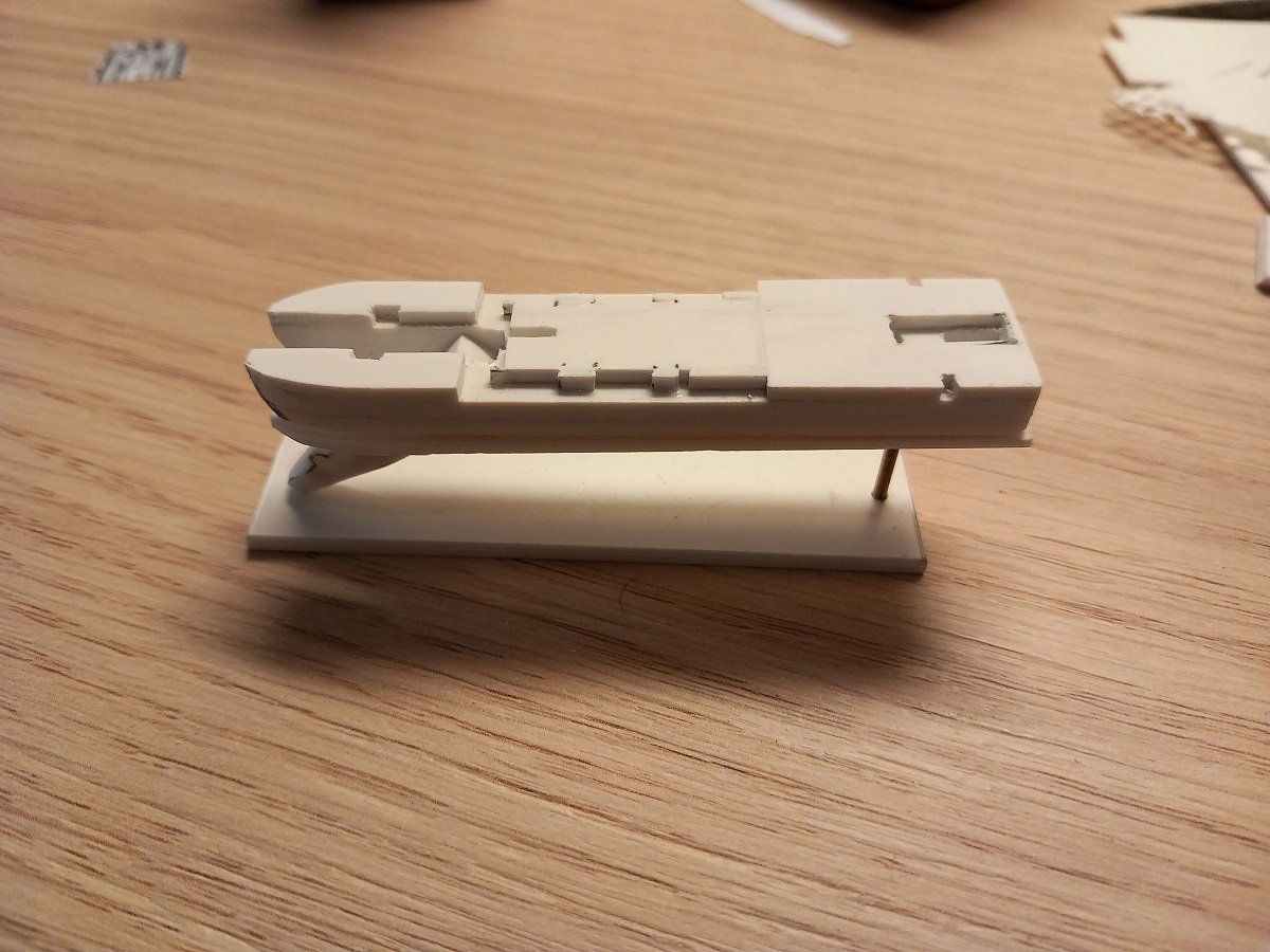
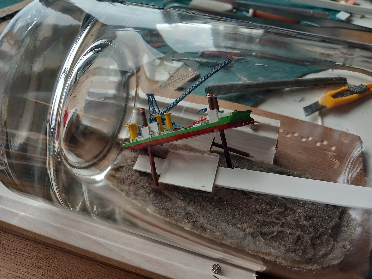
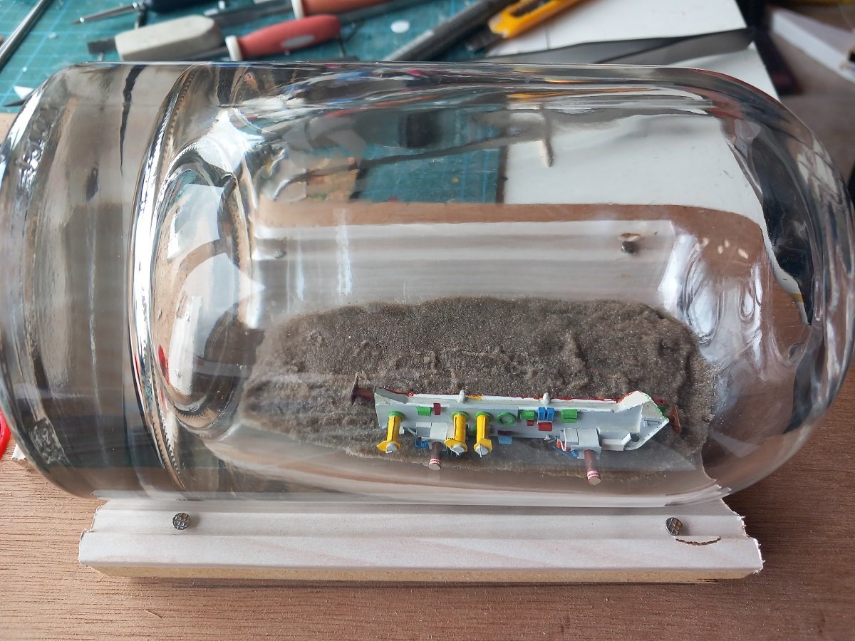
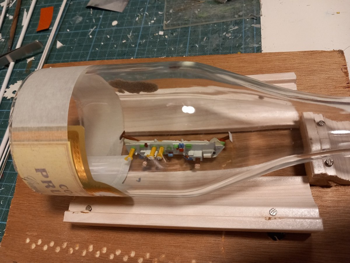
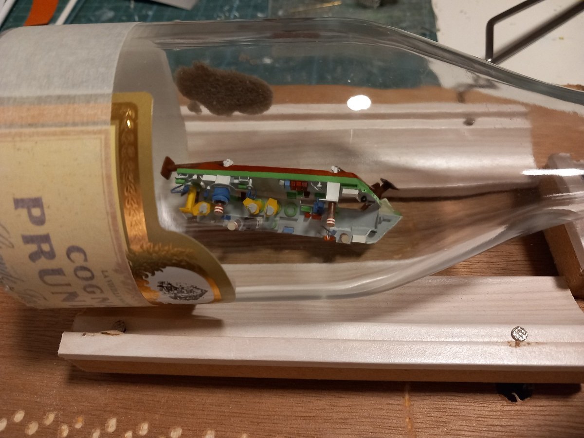
A small update. Started the forward gantry, which is also the limit of my intended bottleneck. I also started the superstructures. However I'm stuck with a semi-finished deck. I can't mount the main deck yet, since I'd need to paint and add additional detail below it. I therefore shaped it a little oversize and keep it in place centered on 2 pins to proceed with further structures. It does mean I can't really mount anything yet. All is dry fit for now. The horizontal part of the gantry is a bit thin and "light", so I'll lower the main verticals and add a thicker and better shaped top part. The ladder underwater is supported by this gantry, so I'll need to make rigging between those two parts. I intend to make that rigging fixed, then hinge the ladder in upper position to insert it into the bottle, then extend it down again once in the bottle, where it will act as the second support. As you can see, I now use a laundry pin to keep the ladder from slipping forward and the ship from leaning over. I intend to glue a fixed piece of styrene to hold that ladder in place and cover that with sand to hide it. The last pic shows the main spud in normal sailing position, this is however just for the placement of the details. I will be displaying the spuds upright.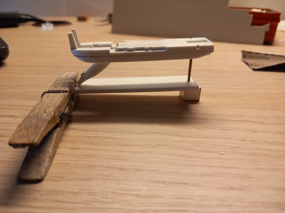
-
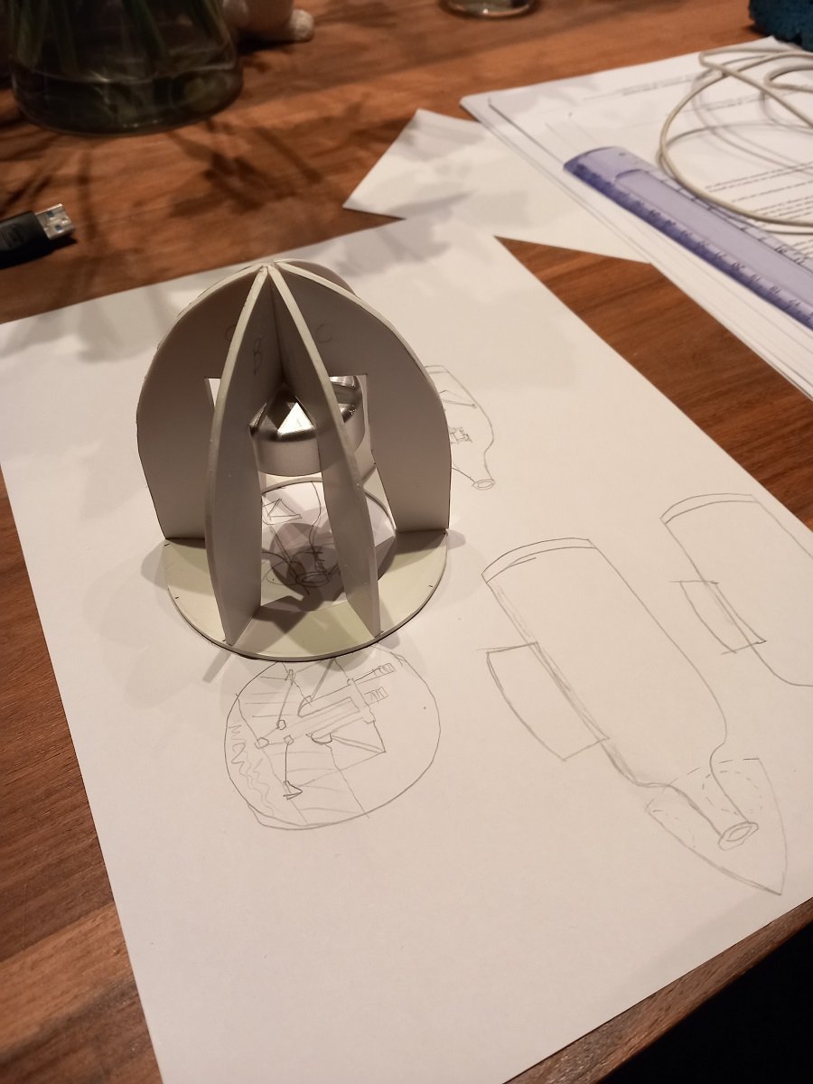
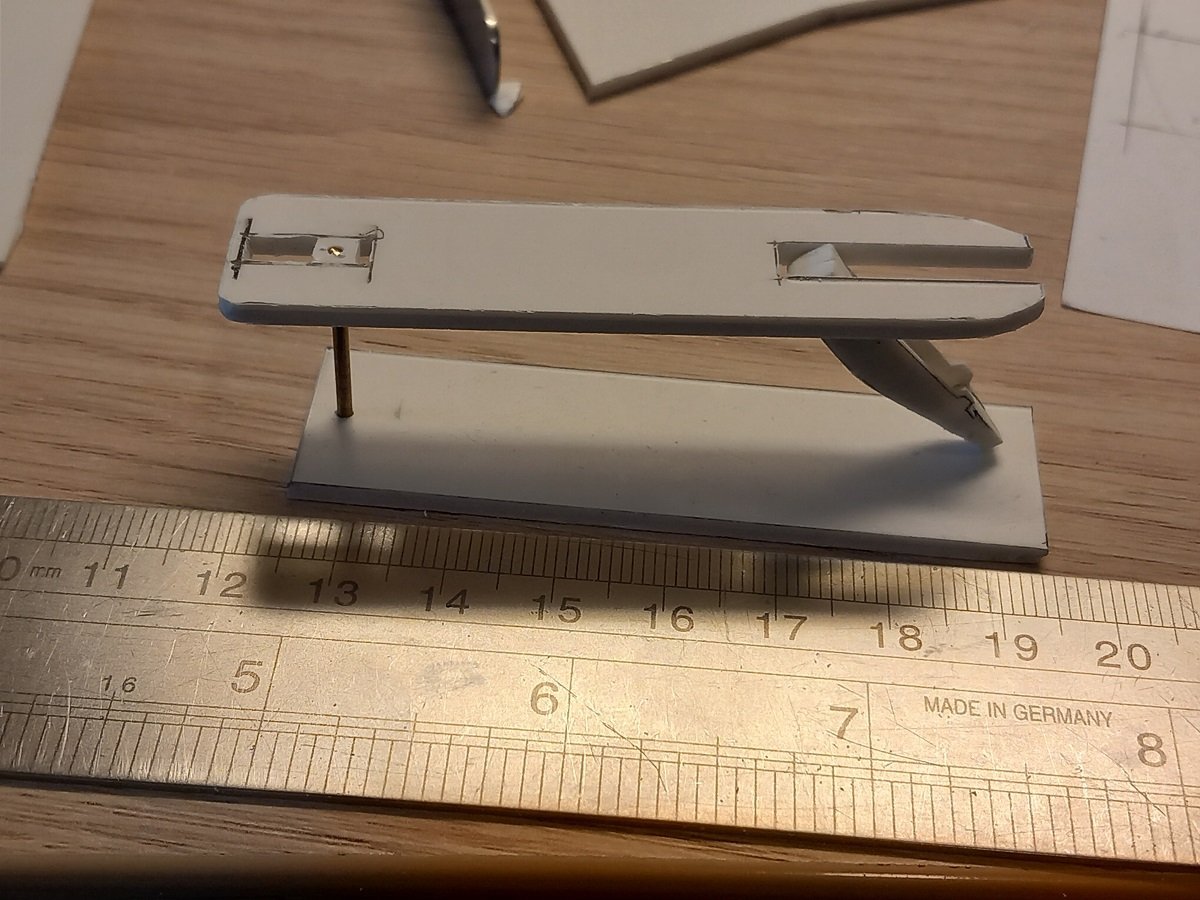
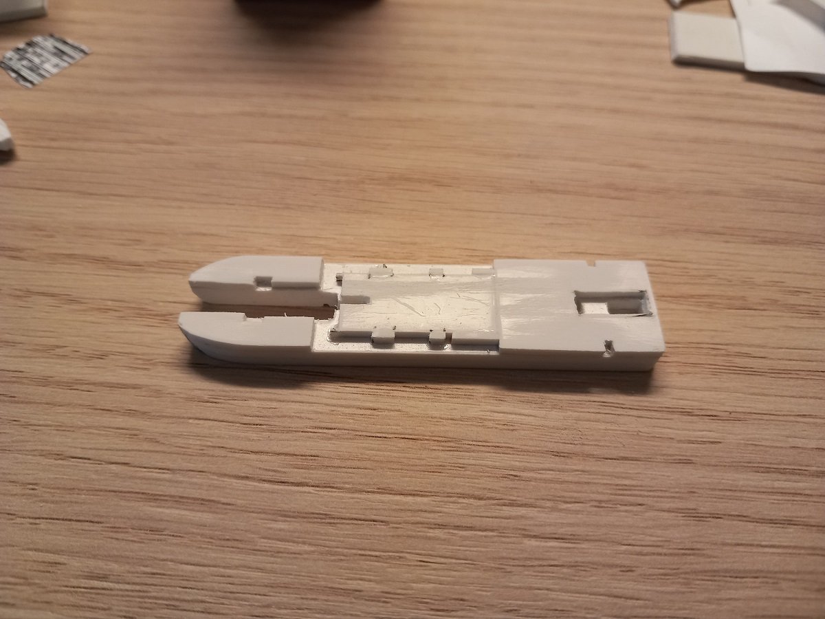
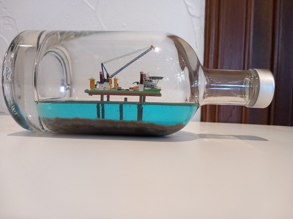
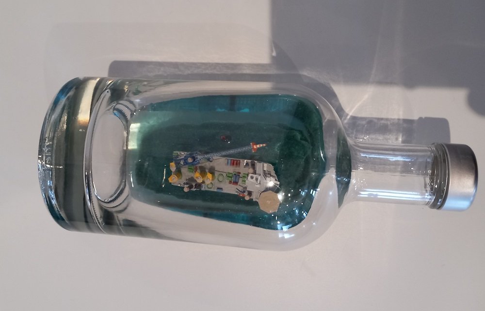
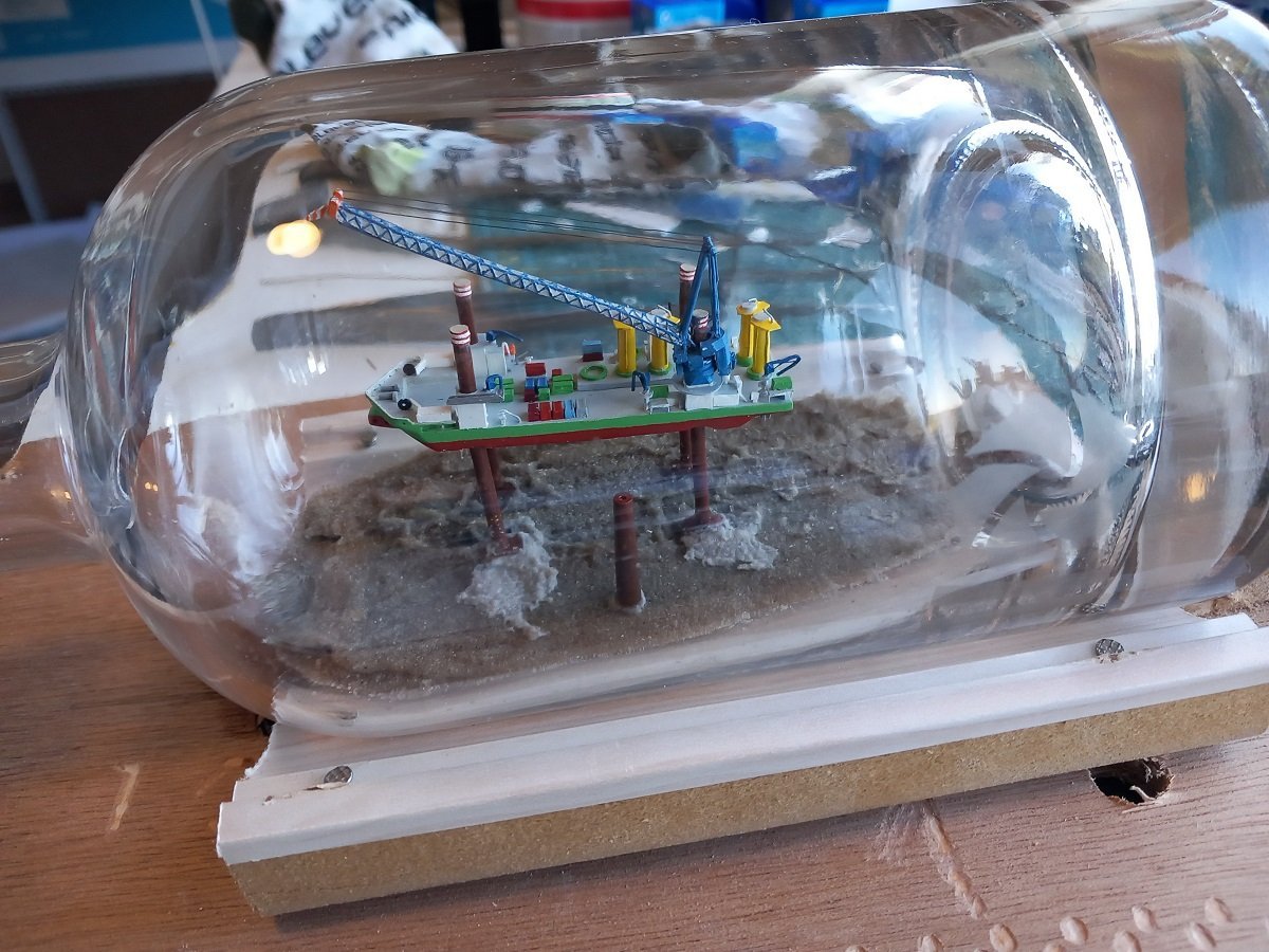
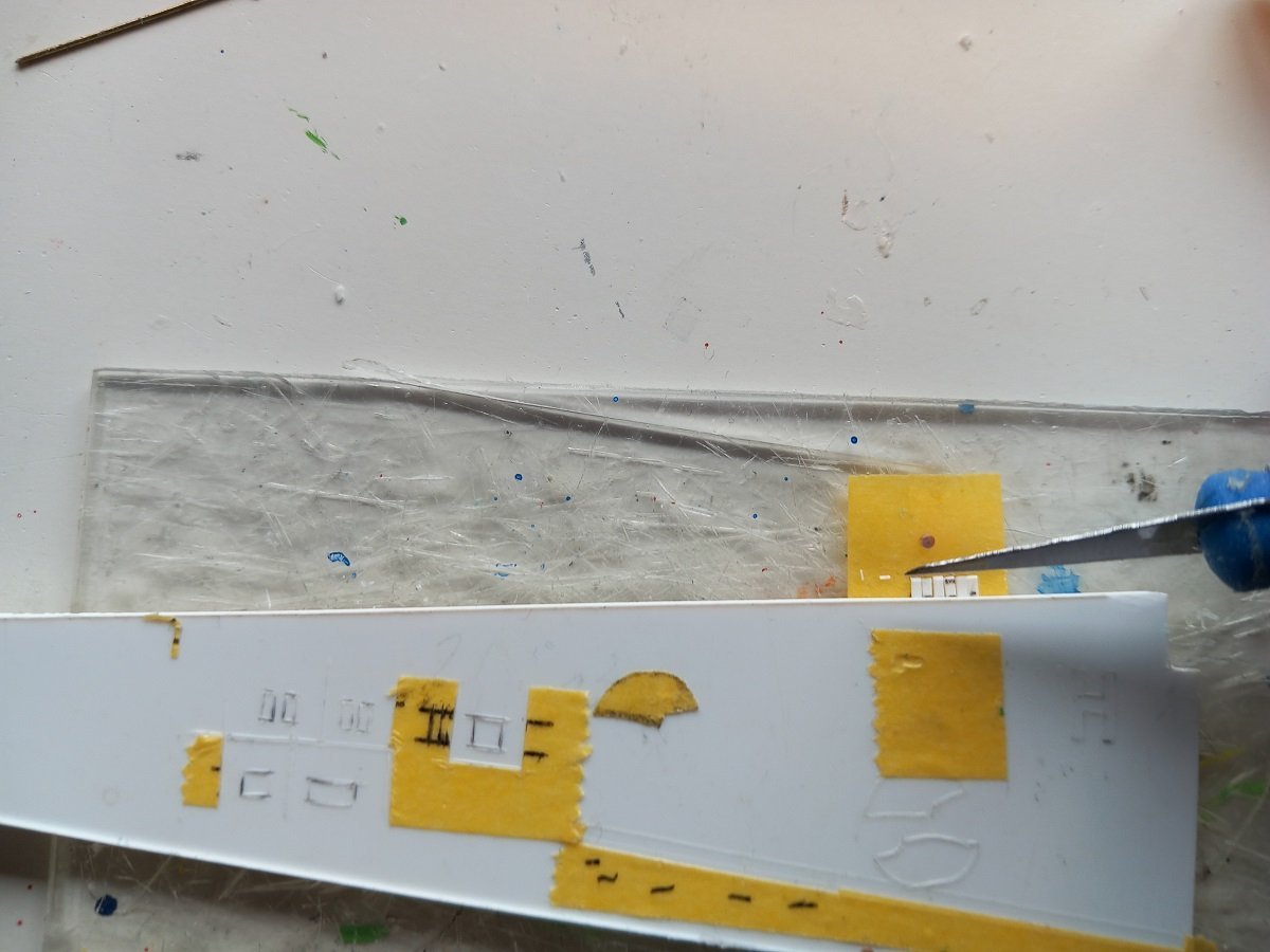
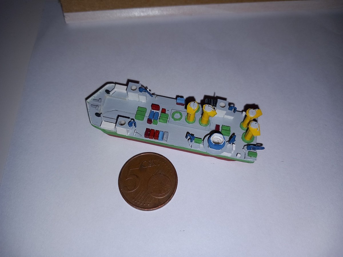
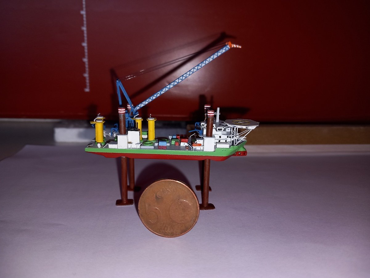
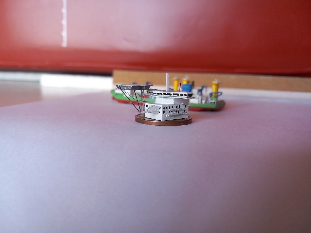
Hi all, Although the Sea Installer isn't quite fully completed yet, circumstances don't allow me to continue on that build. I'm currently restricted to a "mobile modelling set" consisting of scraps of styrene, a couple of knives, files, drills and pliers, so bear with me on my next venture. This time I'm going for the Cutter Suction Dredger Spartacus. The most powerful one of its kind. Practically a big underwater rock drill. It's mainly used to deepen ports or build new ports in harder soil types, where "regular" trailing suction hopper dredgers (TSHD's) can't do the job or where very large volumes of sand need to be dredged to build up new port areas. It's probably the most complex vessel I've ever tackled as a modelling subject and this is also partly the reason I'm going to try to put it in a bottle. In my regular larger scales 1/400 or 1/700, it would become such a long build that I'm unlikely to ever finish it. The tiny 1/2000 scale allows me to leave at least some of the extensive details off. Getting it into a bottle is of course a challenge by itself. I'm not going to "just put it in", I'll be showing it doing one of its operations underwater. I don't have a bottle for it yet, but I'm using the dimensions of the Sea Installer bottle for my reference and design ideas. Here is the website of the beast itself (yes, it even has a website😁): CSD Spartacus I would like to display her when installing/moving her anchors. One anchor hanging free, the other on the bottom along with the cutter ladder (center part supporting the big drill) Spartacus project Overall I'll go for a similar look as Sea Installer, having a bottom part at the bottom of the bottle, with epoxy for the water layer. I will however try to cover the sand with a tiny layer of liquid acrylic gel, hoping to make a smooth transition and either expel or trap any air bubbles before putting epoxy inside. Initial idea is to mount the whole thing on a base plate, which will hold the spud pole aft of the vessel and the cutter ladder forward of the vessel. I would then cover that plate with sand-acrylic mixture and insert it without the spud pole. I will insert it into a sand-acrylic mixture in the bottle to make it blend in. I will then try to mount the lower part of that spud pole in a pre-drilled hole in the plate, so I'm sure it'll stand upright and is held firm. Afterwards I'll mount the ship on top of that spud pole. The hull normally fits into a bottleneck, however, due to the square section of the vessel and its superstructure, I'll need to mount a couple of things separately and other will have to rotate etc. Hopefully an interesting process. Initial effort and size. Start of hull build-up: As you probably noticed, that is one hell of a complex hull. Splitting it could make things a lot easier, but that's not an option here, as the central cutter ladder will have to hinge (insert in bottleneck in "seagoing position" and then lowered to the bottom) and is hanging by wires on the huge forward gantry. I will have to make those in 1 part to make that work. Below is the hinge part for the rudimentary ladder. One 1mm layer is below that to hold it in place. And here is where I currently am. The lower layer in place, but not glued. Since I don't have any paint in my mobile set, I've decided to make a decision I don't like. The ladder needs to be painted before I insert it, however I don't want to wait to continue the hull until I have paint available. I will therefore cut small pieces from the bottom plate, so I can mount that bottom plate, sand and shape the hull, and insert the ladder hinges and the cut out pieces afterwards. I admit this project may be over ambitious considering the amount of detail and rigging all around the vessel and my lack of experience in this tiny scale. It may turn out impossible, but we'll see where it goes.
-
Thanks Auger, your opinion is much appreciated as I, myself, am also still undecided. The hub is heavy, and does draw a lot of attention away from the model. I might go the middle road, keeping the stand, but leaving off the hub. I'll perhaps put the model's details (vessel name and scale) on the front of the stand later on. In any case I'll attempt to complete the hub.
- 51 replies
-
- 5
-
-
- Sea Installer
- Bottle
- (and 1 more)
-
More lanterning, the matt black background is part of the colregs nowadays. It's obligatory to avoid reflections, which would then ruin the angles of the lights. Not sure since when this was part of colregs.
-
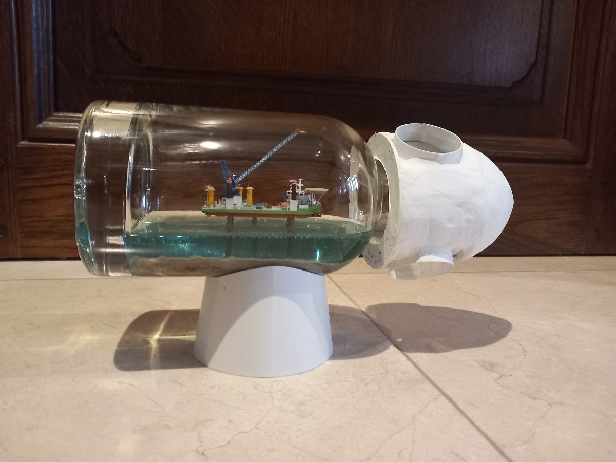
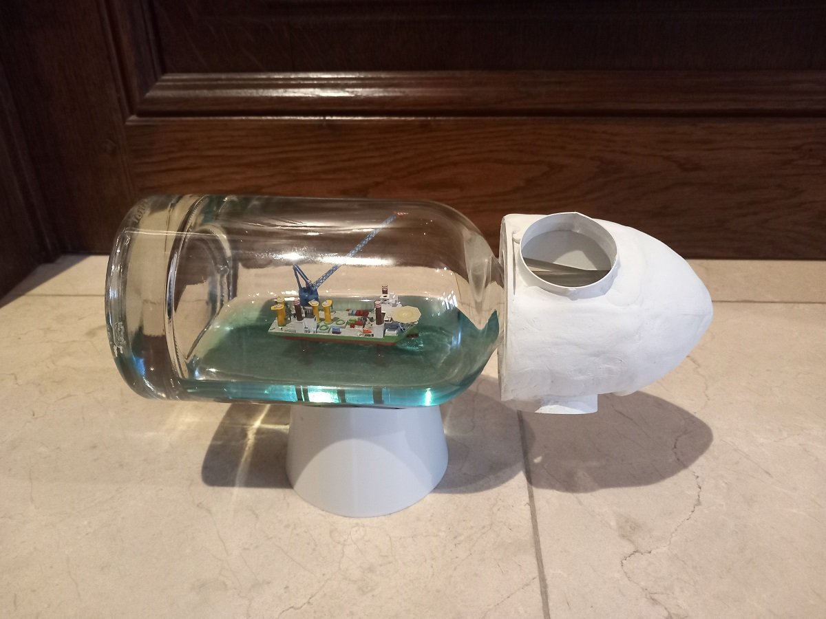
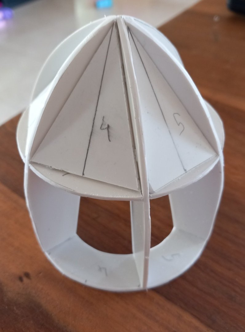
I slowly continued work. Built the base, as this would give a better view on the complete picture. It's built up of a skeleton of styrene ribs using 2mm and 1.5mm thickness. This skeleton was mounted on a base plate and later on a 0.5mm thick sheet was wrapper around that. I first made a paper template for that sleeve. I broadened the initial design a bit, to give more support. The heavy glass bottom plate of the bottle is somewhat compensated by the weight of the hub, so the base can be placed more forward on the bottle. The hub was then further built up with the cylindrical holes and yesterday with two-component epoxy filler. Unfortunately I ran out of filler in the end (the positive side of this, is that for the first time in ages I actually used up a package of this filler before it turned bad 😁). Next up is the first sanding and then I'll order new filler and touch-up (and complete), the filler layer where necessary. After the sanding I'll see if I use a coat of spray filler or just go for regular primer followed by satin white. As I'm going into a busy period, this will go in hibernation for a while. In below picture you can see something I didn't pay enough attention to. Through the hole you can see a rather large piece of the rib around the bottle neck. I wish I had made those ribs less sturdy and visible. Since they are 2mm thick, it's a bit late to decently correct that. On the positive side, I dropped the hub on the floor during filling and it didn't have a scratch...
- 51 replies
-
- 10
-
-

-
- Sea Installer
- Bottle
- (and 1 more)
-
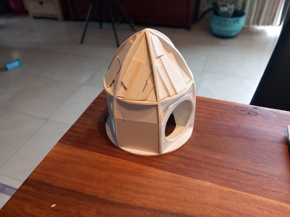
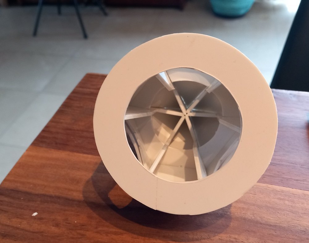
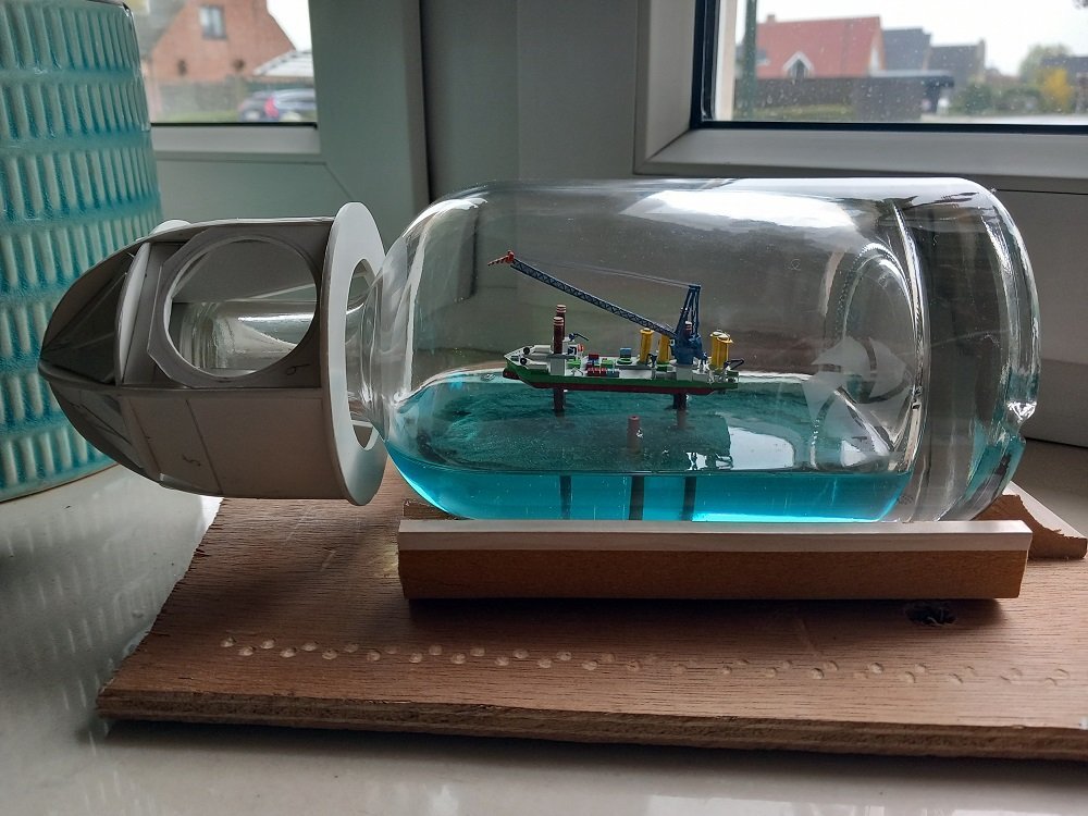
Thanks for the likes. Here's an update on the project. Reached a major milestone now. So the "hub" is progressing. Here you can see the blade entrance holes in place. I'll build up a cylindrical edge from the hole in this straight plate outwards. I will then continue filling some spaces with scrap styrene in order to use less filler. Eventually I'll add the filler and sand it to shape. Here is the inside, which tightly fits around the bottle cap, with the three "light holes" visible. Not entirely convinced of the size though. The hub looks a little too large. It looked ok on my drawing, but then the bottle I drew was actually too long compared to the real one. Somewhat afraid the hub will take too much attention... On the other side, I did decide to complete it, if not for this project, perhaps I'll use it on another in the future. Too much fun not to complete it. And then the milestone, I completed the model itself. In the above picture you could already see I poured the epoxy. After some minor setbacks, like losing one of the small blue cranes etc. I did manage to complete it. I was not very happy with the crane missing hooks and I tested some CA on the small threads, but none wanted to stay straight. Eventually I decided to put the hooks in the uppermost position, basically on the boom itself. At least it's something... The etched sign on the back is not very visible on the pics with a white background, so I'll take some with a better background later on. Time to continue the hub and the support now.
- 51 replies
-
- 10
-
-
-
- Sea Installer
- Bottle
- (and 1 more)
-
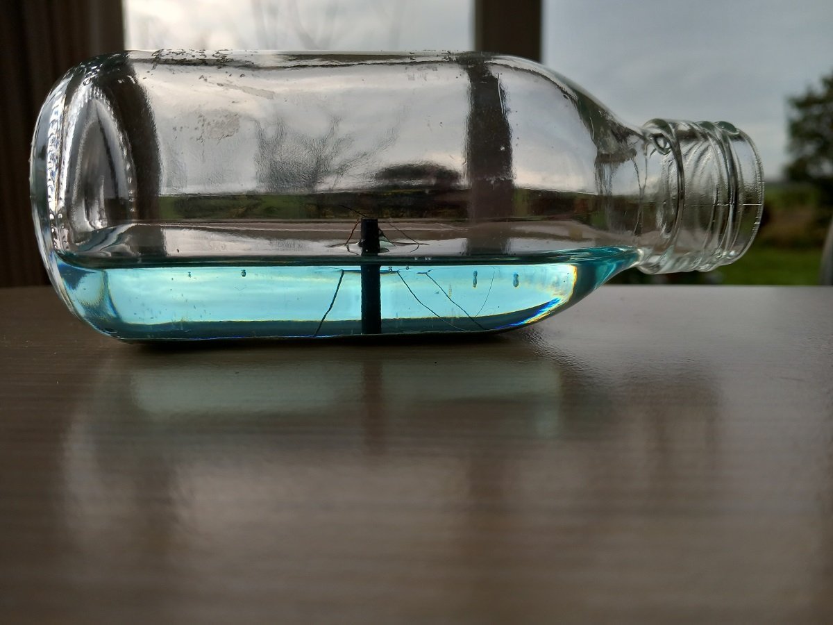
Thanks guys, I've needed to fix those issues, since I did see them. This was in itself quite a challenge. As I feared the accomodation block was indeed loose. Luckily I noticed it and I could remove it without any damage (but indeed no marks of glue on deck, so it didn't sit properly). During handling for twisting that leg, she toppled over, luckily without much damage. Only the wobbly crane was loose, I left it where it was, since there was no real damage. After a lot of effort I did succeed in getting that foot twisted in the right direction. I then put the vessel in my preferred position. I then viewed from the top and marked out the position of the four legs with a removable black marker on top of the bottle. I then moved her out of the way (as far as possible) and put some acrylic-sand mixture straight below those black markings. I then placed the vessel back in position so all 4 feet rested on the drops of mixture. During that manipulation, she toppled again, falling on the gel mixture. Luckily not much was on the vessel and I tried to scrape some off with a piece of brass wire (handy tool really). I also placed the monopile next to the vessel using the same acrylic mixture. After drying I noticed some gaps underneath both portside feet, so I went in again with the angled brass wire tool with additional drops of acrylic-sand to fill up those gaps as much as possible. She's now quite steady, but I want to steady her out further with epoxy before trying to fix the crane and accomodation. At the same time I did some epoxy testing and I've started on the proposed hub. You can see the bottle cap inside the styrene cover (not glued). The initial idea was to cover this with 0.5mm sheet following templates between each set of ribs. Then it dawned on me that you can't bend a surface in two directions at once. So I'm working in basically the same way as I do for hulls, filling up the ribs as much as I can with styrene and then I'll cover it with Milliput. This way will also be easier to get the holes correctly. The "ribs" aren't evenly spaced as I have made 3 wider openings for the holes. That's also the reason there are more ribs. I wanted to just have 4, but with 3 evenly spaced holes, I'd always have interference of at least 1 hole with a rib. So I decided to go for 6 and space them around my planned holes. Here is a picture of the test bottle with epoxy. I also added the Uni Caenis and Uni 8/0 to the mix, to see if they weren't going to be eaten by the epoxy and to see what they would look like in epoxy. The colour is a bit too bright, so I'll add a drop of pigment more.

- 51 replies
-
- 6
-
-
- Sea Installer
- Bottle
- (and 1 more)
-
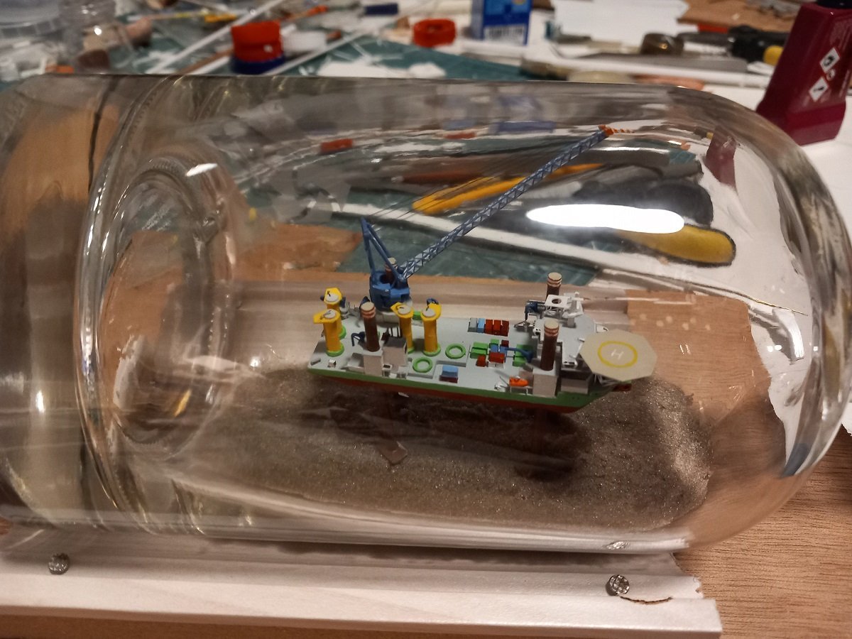
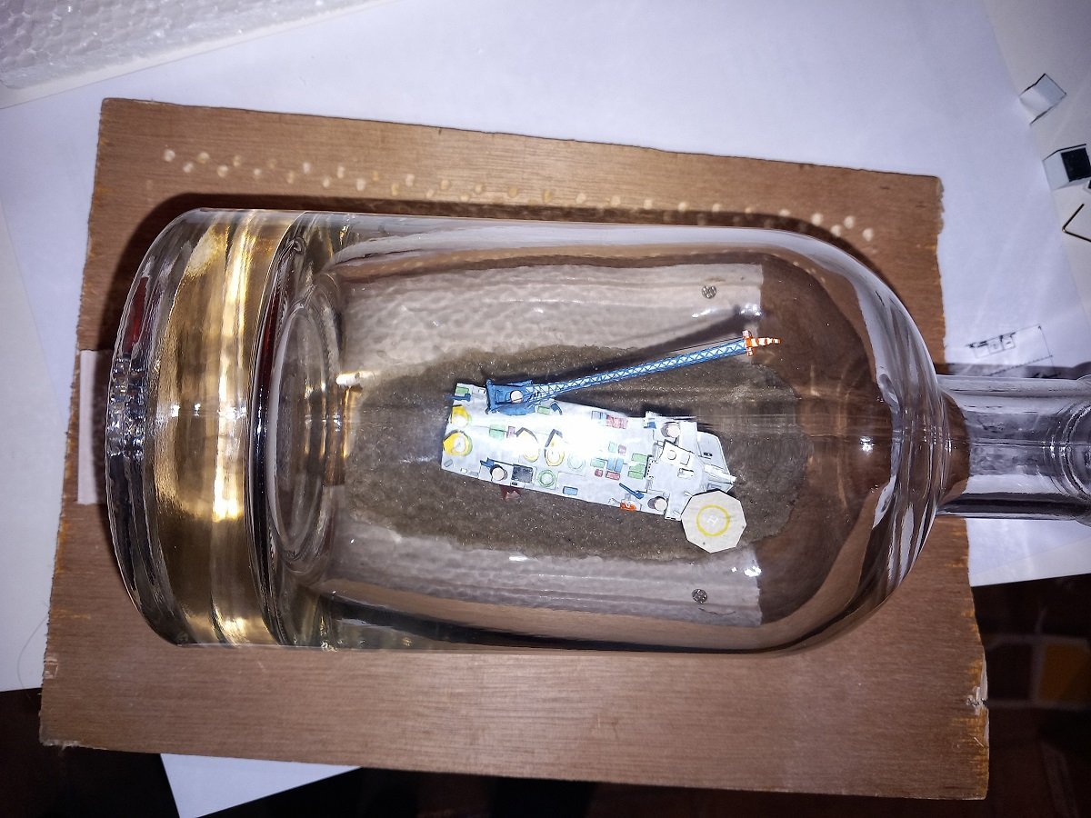
Hi guys, thanks for the all encouragement. Considering point A and B, I knew what to do first! Fix those legs. I used a 0.3mm copper wire pin through a 0.5mm hole, in order to avoid pushing too hard on those tiny legs. This time around, I enlarged one hole to 0.6mm, so I could insert the pin easily in that one. I then used my tweezers on both sides of the hinge to push the pin through. This way the pin is really squeezed in the remaining 0.5mm holes and stuck, even without glue. It wasn't what I call a walk in the park, but at least it went better. Some remaining issues though. 1 is the starboard aft leg is twisted, you can see the foot pointing sideways. the reason is of course the dangly-leg-syndrome. Since the legs rotate when bent, they are rotated when deploying as well. I thought it would be easy to fix that, but somehow it really doesn't want to rotate anymore. Of course it doesn't help that the vessel is still not fixed, on the other side, once it is fixed, the leg is difficult to reach, since the front leg is in the way... Another issue appears to be the accomodation. It went on quite well, going in sideways, turning around onside the bottle, but then it seemed like it didn't really sit down on the hull, the glue didn't catch either. So I'll have to remove it again and fix in back once the ship is fixed inside. The bottom isn't really flat with all the sand and edges, so she's quite prone to topple over when moving around inside the bottle. In the end, she's at least inside that bottle. This time there is no real way back except breaking the bottle...

- 51 replies
-
- 8
-
-
-
- Sea Installer
- Bottle
- (and 1 more)
-
Gorgeous model Keith, we don't get nearly enough models to see of this type of vessel! I also noticed a great improvement in your way of taking pictures throughout your build.
-
Thanks Glen, good to know about the brake cleaner. So, attempt 1 (you know what that means...) First part in the bottle (still yay) Second part attached to first part pretty well, resulting in leg-spaghetti though... No stress though, insert my "spoon" tool underneath and deploy legs by using a small 0.8mm hook made of wire. As you can see in the bottom of the picture, one leg detached. The pin flew out of the hinge, I assume by filing the legs a bit thinner in that part, I probably took off the glue with which it was glued inside... Well, we'll fix that right? Right? Let's continue and fix it later with the long tweezers. That's where the second leg came off. I tried to push down the hull with 3 legs deployed, but somehow the aft one got blocked. After several attempts, the leg detached. I assume the blocking was on a partly detached pin, since there is nearly no clearance between the leg and the "sleeve" in the hull. Luckily I had the presence of mind to take out the crane and split the hull again by putting the tweezer tip between the leg casings forward and aft and pushing it open. The glue hadn't set (that's exactly why I didn't use CA, but using the normal plastic glue instead). I could take out both parts of the hull with only minor damage (one small detail came off, but I could still use it. Conclusion of the ordeal: A. Those pins are a problem B. Those pins are a problem C. Tweezers are ok, but if your ship is not centered in front of the bottleneck, they are much less useful. Under some angles, they block and you cannot open them. You can also rotate, but not move up or down anymore under certain angles. "Fixing" that one leg when it came off, would probably have been a very difficult task if those 3 other legs had deployed properly. D. Whatever sequence I use in the future, I will try to fix the ship in place as soon as possible before continuing any additional construction. Working with 2 tools through the neck is possible, but difficult nonetheless. E. Whenever things go wrong, try to get back to start, don't push ahead
- 51 replies
-
- 4
-
-
-
- Sea Installer
- Bottle
- (and 1 more)
-
Time for the last preparations for bottling. I did a test with the hull parts to see if my sequence was feasible without too many damages to my detailed model. I used my opened-up test bottle for that. I had some issues with the dangly legs, they'd tangle a lot and weren't sliding in their sleeves too well. I made some adjustment to those parts of the legs with a file for easier deployment. Next up were the Voight Schneider propellers. Basically horizontal paddle wheels. This ship has 3 of them. I used some fine Evergreen strip, cut up and glued to a 1mm central hub/disk. The brown part on the masking tape is the central disk, the small strips were cut to size after lining up on masking tape. Here is one of the VS props assembled. When the glue was dry, I pried it off the tape by simply inserting my tweezers under the tip, this lifted the edges of the prop free and I insert my knife tip underneath to pry it loose without damage. I made the separately because I was affraid of handling the model if I were to glue the strips separately on the model. Once they were assembled, I glued them on the disks that were inserted in the hull at the start of construction. Time for bottling, epoxy testing and developing that hub for the bottle (yes, I did decide to give it a try). One question for @Glen McGuire, do you reuse your hose and funnel for pouring the epoxy, or do you use a new one each time?
- 51 replies
-
- 3
-
-
- Sea Installer
- Bottle
- (and 1 more)
-
Great job Glen, love the water effect and a funny solution for the water coming out of the bottle! The water and waves appear in scale with you Kraken, which is not an easy thing to accomplish 👍
-
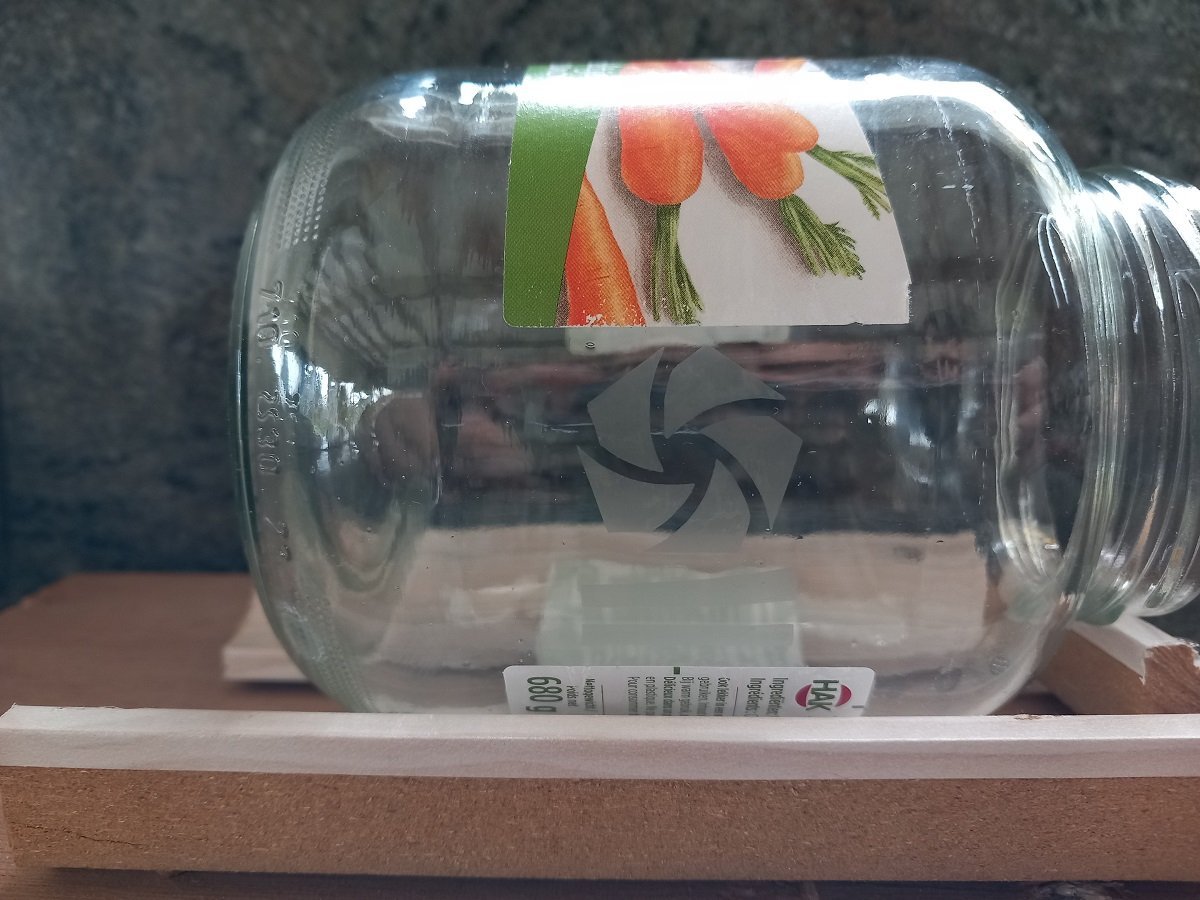
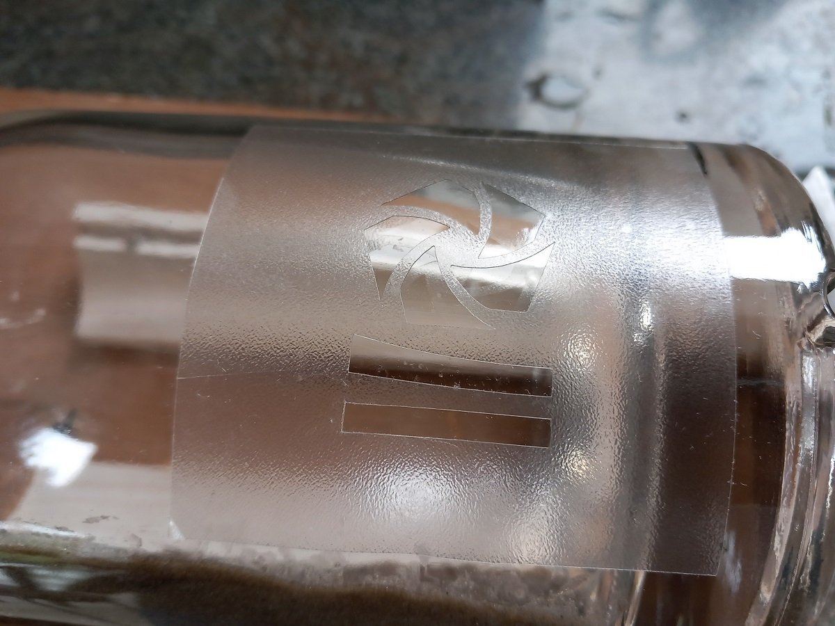
So I did get my etching cream already, so I did a test. Went nicely, now we have a DEME pot of carrots. Unfortunately, the actual etch went wrong (somewhat). You can see the mask on the bottle in following picture. However, it didn't want to straighten out, which, with a mask from the same material, it did perfectly with the pot of carrots. I believe the bottle isn't as smooth or straight as it's supposed to be. So the mask in the picture was discarded, since I didn't want to take any risk. I made another one, stuck it to the bottle with more success, it still wrinkles, but they were located outwards of the logo. During etching however, one of those wrinkles spread out towards the logo, my conclusion is that the vinyl I used, is probably to stiff for this application. If it would have been more flexible, it wouldn't have straightened during etching... All in all there was only a small bleed and since it's in the back of the bottle, I'll proceed. Next thing is putting the ship in the bottle. Be warned, etching stuff is kind of addictive, I want to etch all kinds of stuff on glass now 🤪
- 51 replies
-
- 5
-
-
- Sea Installer
- Bottle
- (and 1 more)
-
Lots of progress now. At this point I'd say we're at 99% of the model itself. - Gave her the auxiliary cranes on each leg and around the deck (you don't want to move a pallet with that big crane) - Dressed her up with her deck cargo of transition pieces, since they'll pass the bottleneck - Gave her additional containers all around as these vessels carry around a lot of stuff. Still considering if I'll add some reels as well. All in all I'm already happy with the seam camouflage 😁 - Almost completed the accomodation, crane jib rest, helo deck etc. Some small paint jobs remaining. - Crane was rigged with Uni Caenis thread. I also bought Uni 8/0 as well as Veevus 16/0, but the Caenis is clearly the thinnest. Surprisingly the Uni 8/0 appears thinner than the Veevus, although the Veevus is claimed to be smaller (or I'm just cross eyed, which is possible after this rigging job). She's of course a lot smaller in reality than on these pics. I've also ordered some glass etching cream and intend to etch the company logo on the bottle. (yes stole that idea from a pirate ship on this forum somewhere as well). Of course I'll first test that on a test bottle.
- 51 replies
-
- 7
-
-
-
- Sea Installer
- Bottle
- (and 1 more)
-
You do know what's missing, right? No, ain't talking about penguins... water that runs off the edge of the bottle opening! either running straight down or into a slight bend in the direction of Kraken's mouth... I'm thinking mixing clear acrylic gel with the same pigment as the epoxy? Or building it up externally from epoxy and then gluing it in place at the opening? Just saying though... Fantastic job so far!