Javelin
-
Posts
632 -
Joined
-
Last visited
Content Type
Profiles
Forums
Gallery
Events
Everything posted by Javelin
-
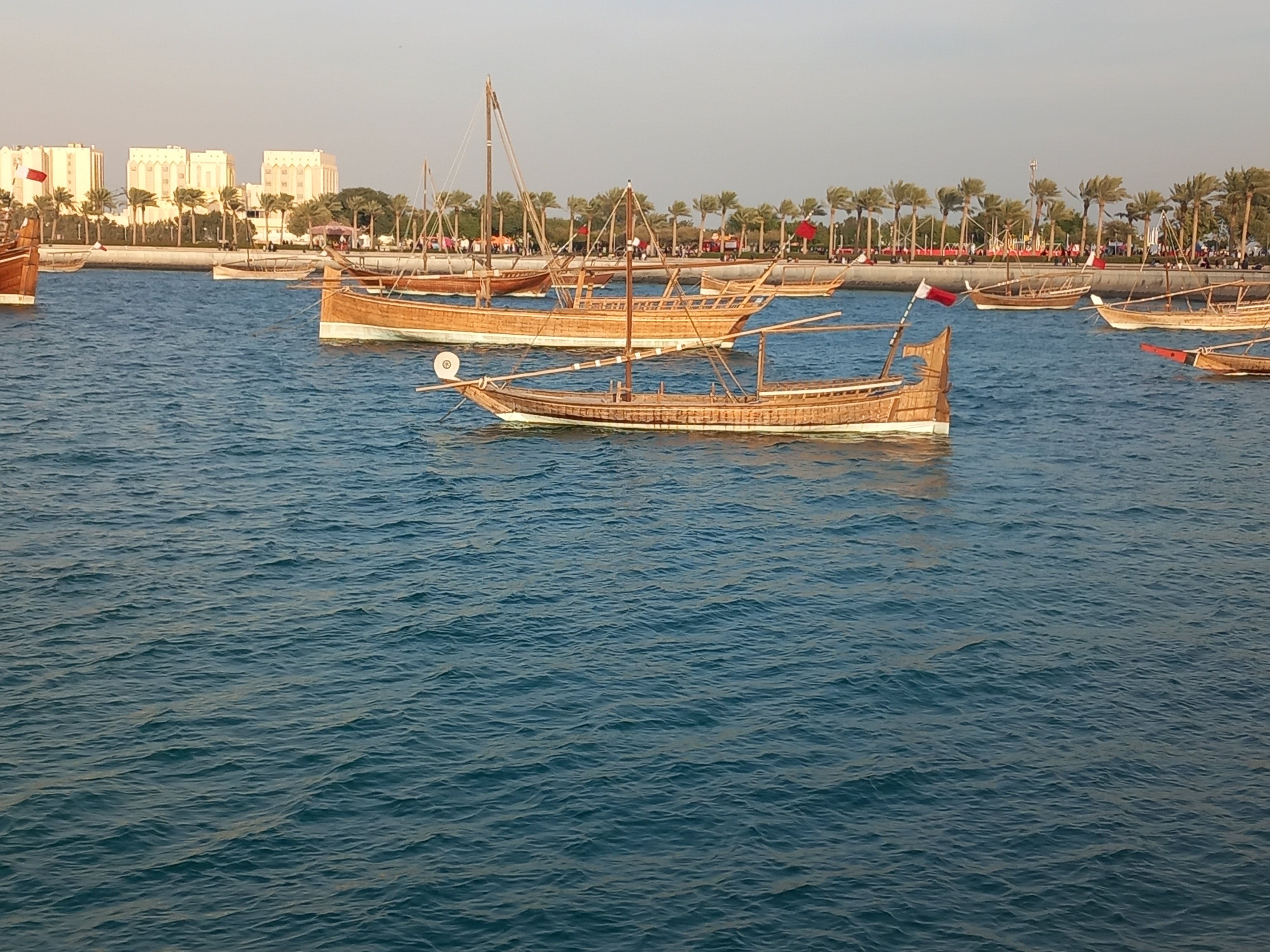
 A lot of original Dhows are anchored in the bay around the Museum of Islamic Arts in Doha as well. Not sure if they can be visited. I found them anchored for the national holiday, but not sure if they were brought out for the holiday or permanently (inaccessibly) anchored.
-
Unfortunately I have to agree with Ferrus. Although nowadays safety is improving, a lot of "old school" people are still around on work boats. The drive to perform and do things quickly is often that high that people ignore the hazards to their own life and limb. Very often they are not aware of the hazards or have gotten away with some practices for a while not to consider them dangerous at all. When at work, tools are often scattered around to avoid losing time to get them. A lot of it depends on who's leading the operations and which kind of mix of characters you have onboard. All in all the rate of injuries and casualties on workboats remains high, even today, and that's not entirely due to the inherently dangerous activities they perform... That said, I'm happy to hear of the good news (considering the circumstances) about your health Keith! Great to see you continuing Lula!
- 732 replies
-
- 8
-

-

-

-
- Lula
- sternwheeler
- (and 1 more)
-
Nice project, this is perhaps also an interesting lead interesting for you. Kuwait Maritime Museum
-
Phil, She is looking brilliant, perfect really. I can not describe it any better! Nowadays the buoy is brought onboard first, however, the buoy in our days is connected with an anchor hoisting wire. So the wire between the buoy and anchor is dedicated to hoist up the anchor. The second wire is the one actually holding the ship/object that is anchored. In your set-up this is very different of course. It does however seem logical to get it out of the way first, since it would defenitely tangle with the anchor and anchor hoisting rope while hoisting the anchor. Something to do with your good friend Murphy.
-
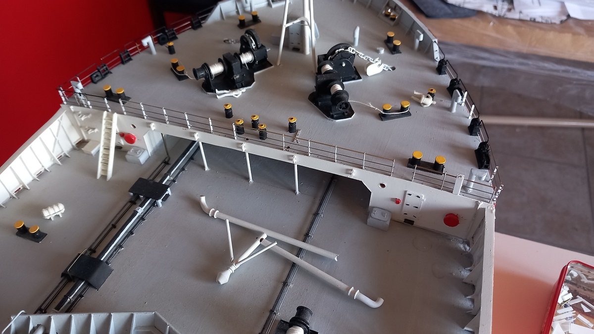
Thanks. Now came an example of "no matter how long you think about something, sometimes you just need to do it to figure it if it'll work". For a very long time I've been holding back that railing on the forecastle until I was finished with that ventilation pipe and mast. The idea was to have that mast with its supports in place and then figure out a way to get that railing correct. Well, that didn't work out the way it was supposed to. In the end I figure it's better to first have the railing in place and then just fit the supports. They were interfering with each other, without a real way to avoid it. Now I have the railing, so I'll just need to close the drilled holes and redrill the holes for those ventilation trunk supports in a different position to make this work. In the end I'm still happy about it as we're still making progress. The ventilation system was dry fitted after all, so no real issues apart from filling and drilling.
-
I do think you could have mounted it upside down and cut along that keel, slightly off-center... However, you clearly passed the test and have overcome your challenge. I also don't like cutting a good hull, so I cut (by knife) each layer of the hull before gluing them together. Having a bit of a Z-cut along the hull in the vertical direction also makes it easier to line up the hull halves. It also prevents the loss of width created by the sawing and loss of saw dust. In any case a brilliantly obscure subject again! I do believe you have all the tricks in your box to bring this one to a good end. I guess it'll resemble the trireme in a way. A good series to watch for this sort of lesser known vessels is the South Korean tv series Yi Soon Shin. A very well made series with a lot of naval action between the Japanese Navy and Korean Navy in the period where the turtle ship was invented. Yi Soon Shin
- 106 replies
-
- 6
-
-
-
- Kentoshi-Sen
- bottle
- (and 1 more)
-
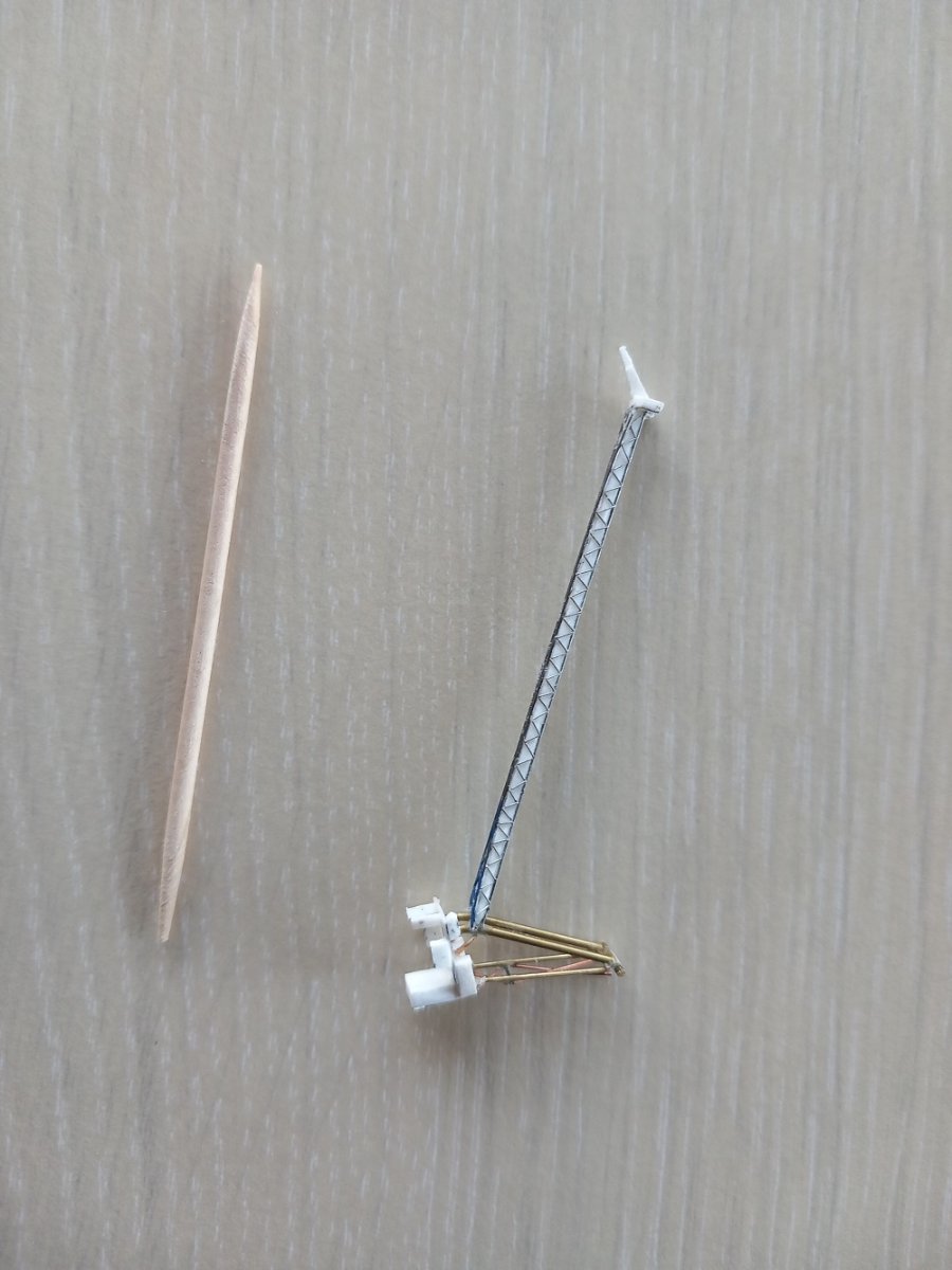
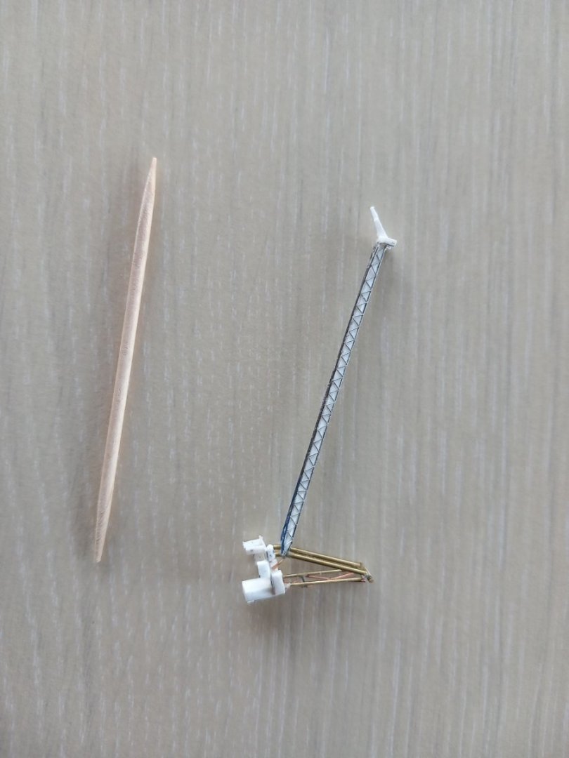
I'm having some difficulty imagining the scale we're look at, but it might be worth a try to modify your current version with some tiny copper wire of various thicknesses to add a bit more complexity. (or build it up entirely ftom such wires, using CA as a filler between the wires) Depending on size, most people won't notice the joints after all. I'd probably glue the end of a 0.1 or 0.2mm wire to your carved piece with CA and then bend it to the required shape/curl that you need. Then cut off excess and glue the curl down. I find using slow curing CA easy, since it flows less around and allows removing excess glue for a while. I generally use stripped wires from power cables of telephone and other electric/electronic appliances. You find a variety of thicknesses between 0.1mm till 0.3mm wires like that. I'd have a go myself to better explain, but don't have access to my equipment at the moment. Below you see a built up crane jib from such wires. They can be bent very (too) easy and cut with any regular fine tip scissors. Crane Sea Installer
-
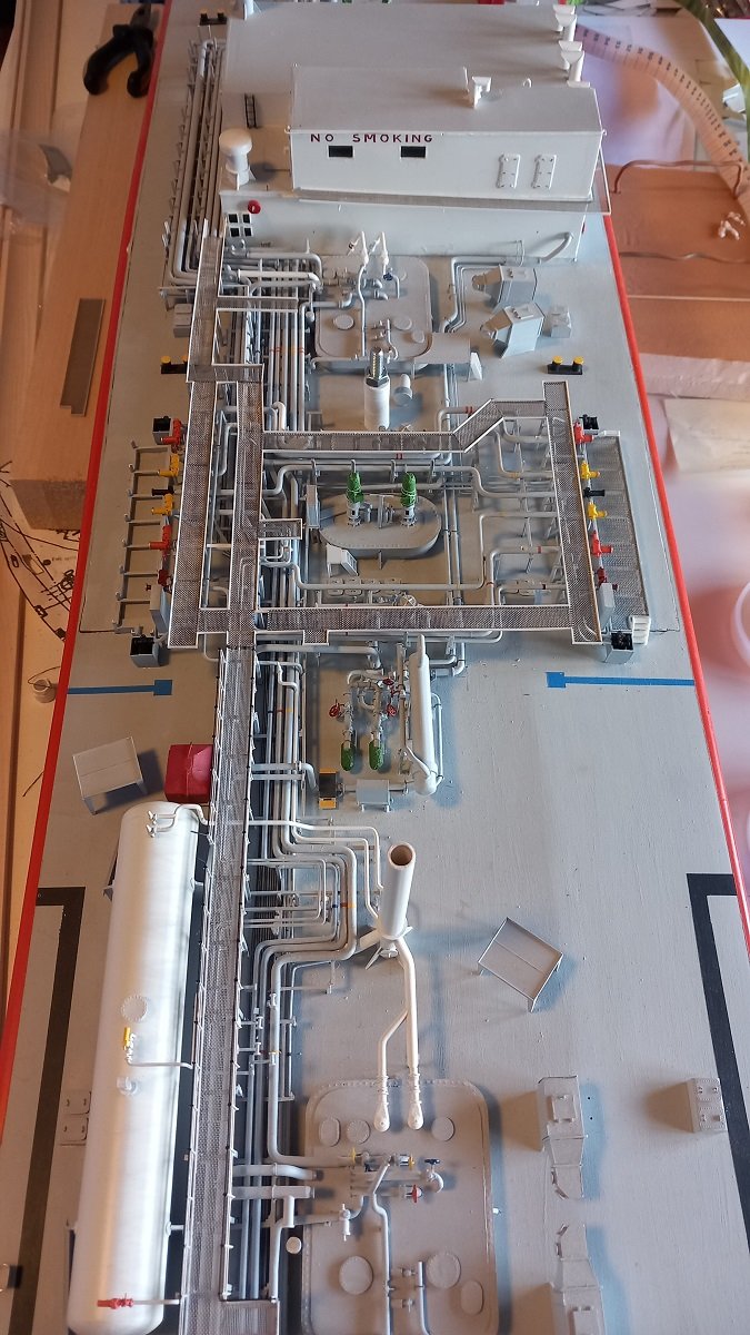
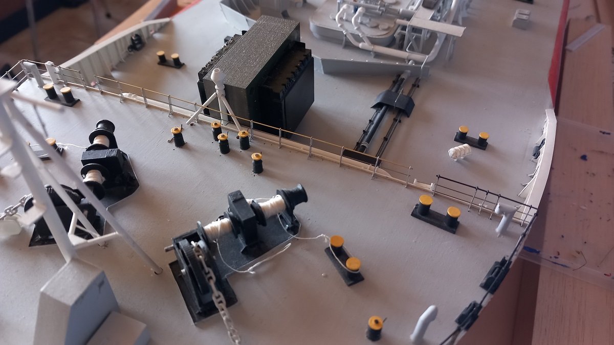
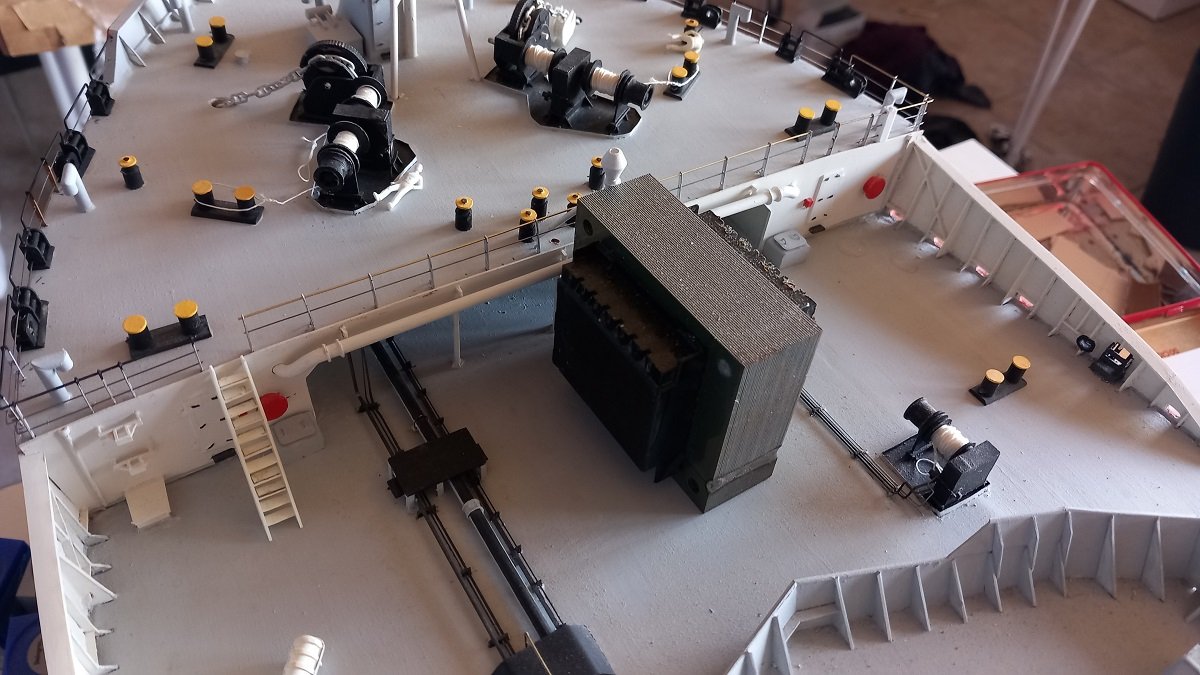
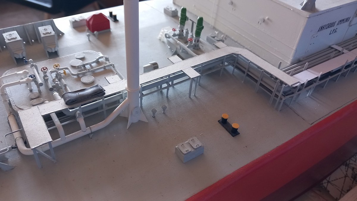
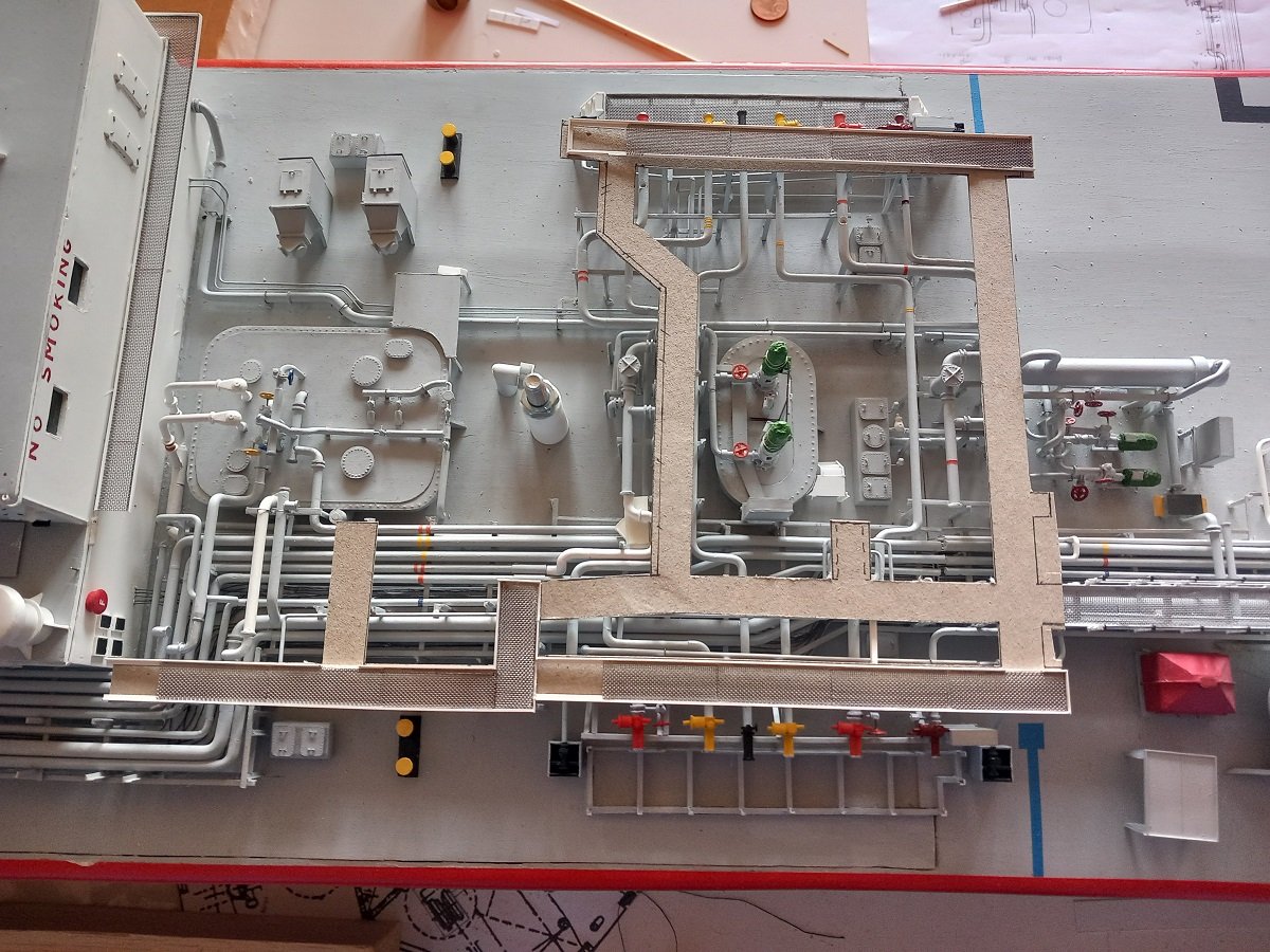
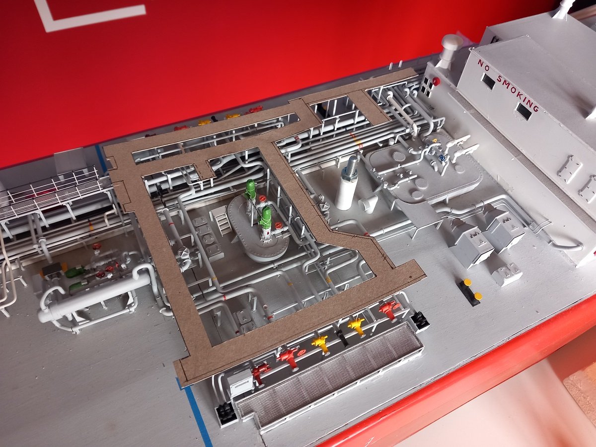
Well @Jim Lad, I do believe this was one of the lower priorities in the design and just added "as they went". There were no 3D browsers to check for their overall design and access etc. back in those days. Nowadays you can walk through a design before its built and see if a person fits in a certain space to repair etc. (yet they still screw up from time to time). My slow pace continued and just as I was getting productive, my leave's getting cut short... At least some progress was made. The catwalk part in the center is now complete, next step will be to add railing. And work on that forecastle continued. In the meanwhile I decided to continue in the fitting of the remaining catwalks. The forward edge of the finished center piece is actually a step. The catwalk forward of that edge is lower there, the level being determined by the forward part of the catwalk. So I now made a cardboard template for that forward part. And I also have a first paper design for the last piece alongside the compressor room. The support beams of the piece alongside the compressor room are actually much wider than the catwalk itself and are welded on one side to the compressor room. That's the reason the paper is now laying down. Once I finish and install the forward part, I'll start adding the support structure next to the compressor room at the determined level. This area is probably the least photographed part of the vessel and amongst the 1000's of pictures I have of the vessel, I only have 2 or 3 of this area... As you can see, the drain piping around that compressor room is quite complicated and has also received a few punches over the years. I'll need to fix that at some point. Also the piping connections entering and leaving the compressor room are just forward of the door, I first need to add those connections before I can actually get the support beams in place.

-
It's beautiful. Which type of wood did you use?
-
I'm also surprised you don't get many comments (but also guilty of not frequently making any 🫣). Makes you probably the most underestimated modeller of this board! Definately considering your pace of construction. Great job on those stern decorations! I'm with Steve on that coppering as well, very sharp result.
-
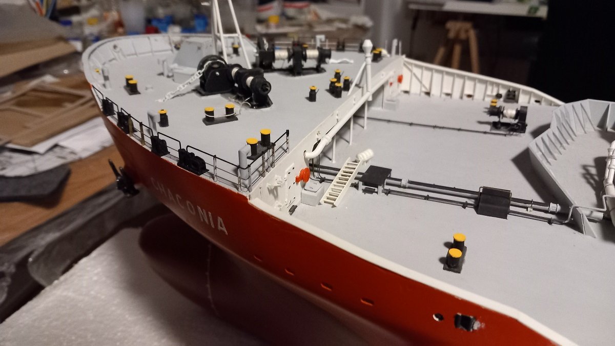
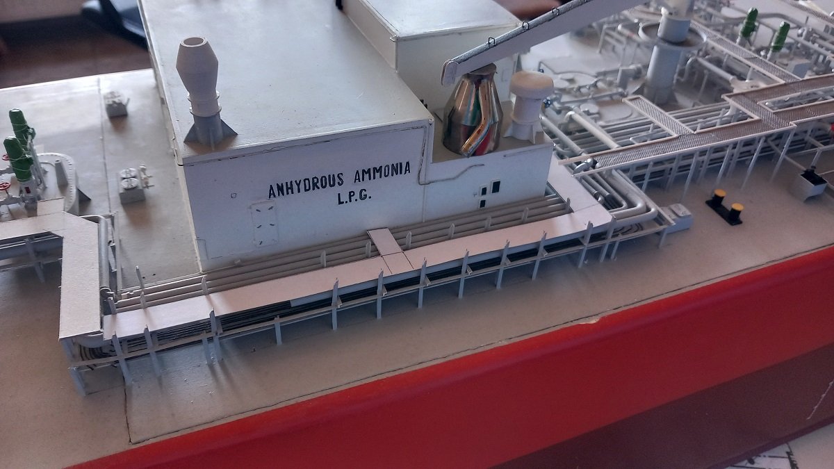
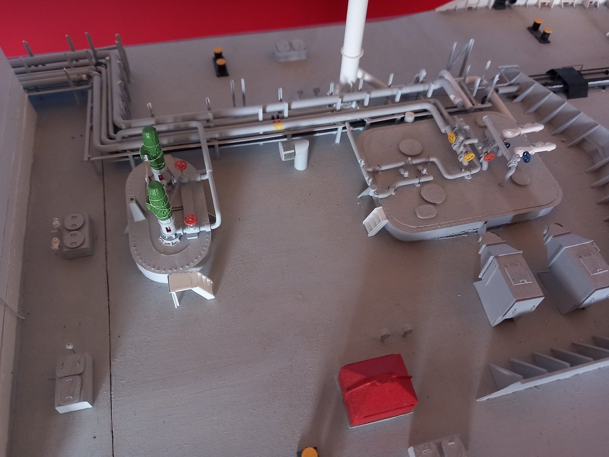
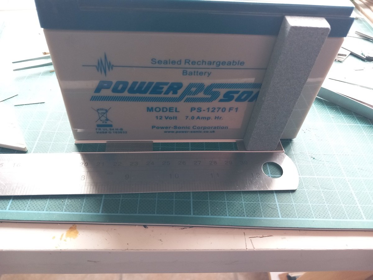
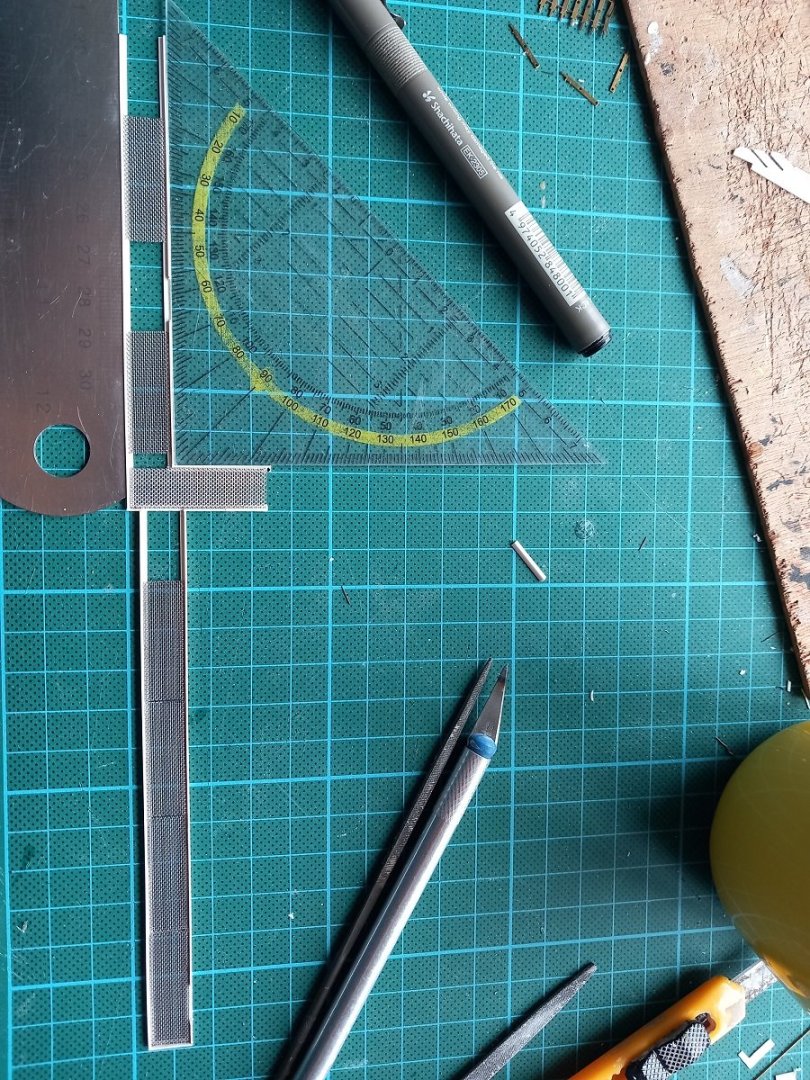
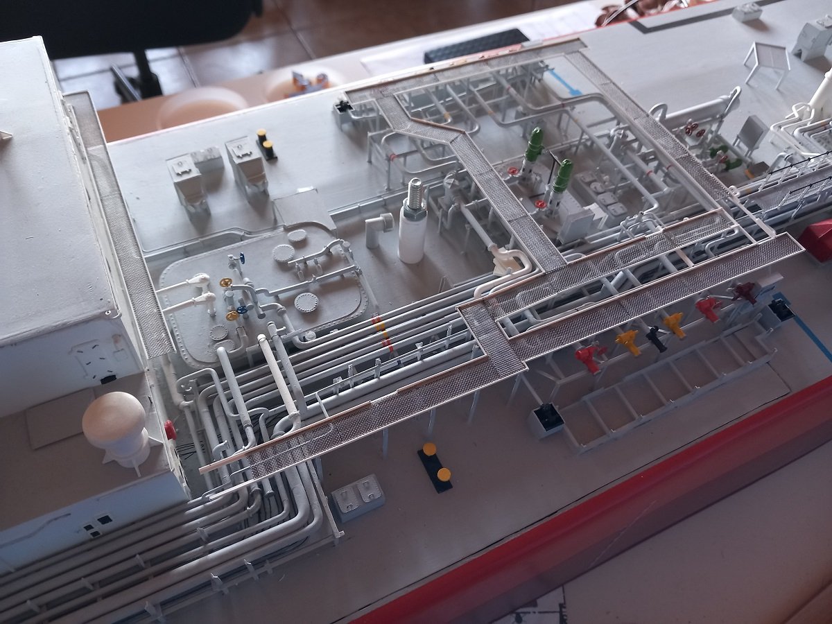
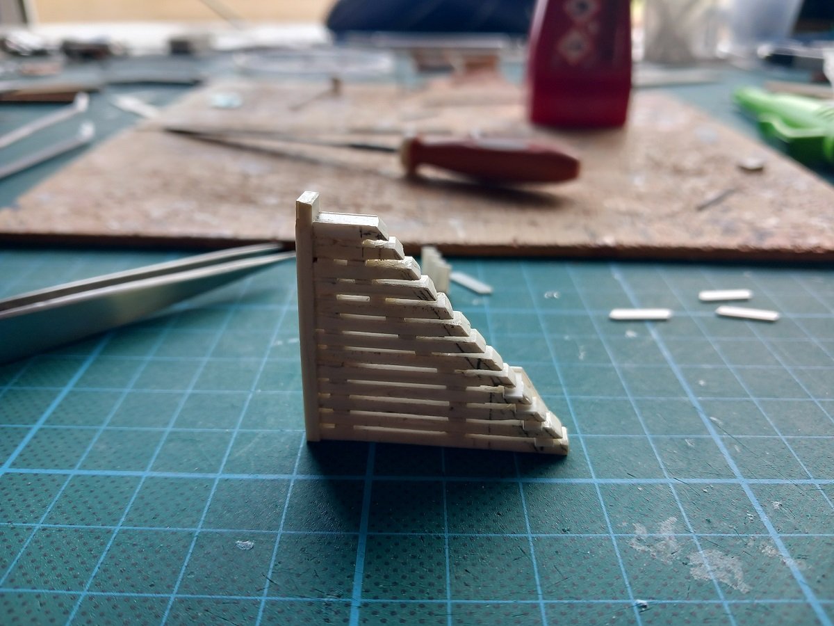
Thanks for all the praise, it really is too much coming from builders like yourselves! It's all a bit crooked and far from the sharp level of modelling you mostly display! Unfortunately not much progress was made. It's not a real builder's block, since I'm still working on it, but priorities have shifted a bit and for this kind of detailing I need long stretches of time in which I can fully concentrate. Those long stretches of free time are missing at the moment. However some progress is made wherever I can. Not in the pictures, but I did also start making that railing on the portside forecastle to eventually finish that area of the vessel. This basically involves drilling the fairleads, adding stanchions and going from forward to aft, it only takes about 15 minutes for each, so I can do that when time is short. However, the main activities in the past weeks were those little stairs/platforms. Each pump dome has a platform with a stair: Here you see tank 1. The stair on the vapour dome (forward, rectangular thing) still needs feet. Particular to these areas is that the tank dome are part of the tank and the tank is independent from the vessel structure. It basically sits inside on supports, but is not welded to the vessel. All this is done because of course the tank shrinks quite a lot when it is cooled down from ambient temperature to the low cargo temperatures. Underneath the skirts around those tank domes is a big rubber connection to keep the space around the tank air/gas tight. All this means that the tank dome comes down when the tank shrinks and comes back up when the tank is heated up, so there can not be any fixed/welded connection between the vessel and that tank. The stairs between the main deck and the tank dome are therefore fully resting on the main deck. Hence the need for these platforms and legs. A logical thing when you think about it, but very often still mistakes are made in shipyards where they do connect things like that... And as @Jim Lad rightfully mentions, those catwalks are also complicated. I've made steady progress on the most complicated part. A constant sequence of fitting, adjusting, fitting again, etc. In general I build them this way to get some rigidity in it. Two flat lines are used (in this case the side of a heavy battery and the steel ruler) and a small weight (in this case a sharpening stone) to push the grating into the glue. I use multiple sections of grating to keep the, often bent, plastic L-shaped parallel, while I glue the first piece of grating. Afterwards I make my way forward. The intersections are chosen to create maximum strength in the direction I want it, be it longitudinal or transversal. As long as it's not complete, it's wobbly, so I use the cardboard template to test fit it. It's a very delicate fit, since I don't have anything to really hold it in place. It's not only longitudinal or transversal fitting, but also rotation, I need those catwalks to be parallel to the centerline as well. And since it's extremely light, it shifts off the supports the moment I touch it. That said, the main part is done. It's now "self supporting". As you can see the forward edge is not finished yet. Next step is now measuring and finishing the aft edge, where it connects to the existing catwalk. When that is done, she's "fixed" in the longitudinal direction and I can cut the forward part to length and finish it. It also needs 3 additional smaller platforms that lead to stairs, those will follow afterwards to make sure they are resting on their supports. After that it needs railing and that is a very time consuming part. I also noticed I'm going to be short of PE stanchions for my railing... And probably by a LOT. As a last note, you also see that complicated bended pipe (unpainted) that I needed to make. That was a rather impossible part to bend in one piece, so I had to build it up out of several pieces. Still not fixed though. There's another, easier one, towards the back, but it's not in the picture.
-
The aft part seems to be bolted on and has the same shade as the hub, so I assume it's also brass (blades also seem bolted with their base to the hub). The forward shaft clearly has a different shade, I'd guess steel, but I'm not too familiar with that age in shipbuilding.
-
Actually nowadays they are painted matt black by colreg regulation. The reason is that it shouldn't reflect the colour of the light at all, simply because the light would then be visible from unwanted angles (in case of sidelight that would be from angles too much astern). That said, I believe that only came into use in 1970 or later, so for Lula I guess it's really up to you. In any case this thread is great to follow, so much detail on such a small model. She really looks the part!
- 732 replies
-
- 5
-
-
-
- Lula
- sternwheeler
- (and 1 more)
-
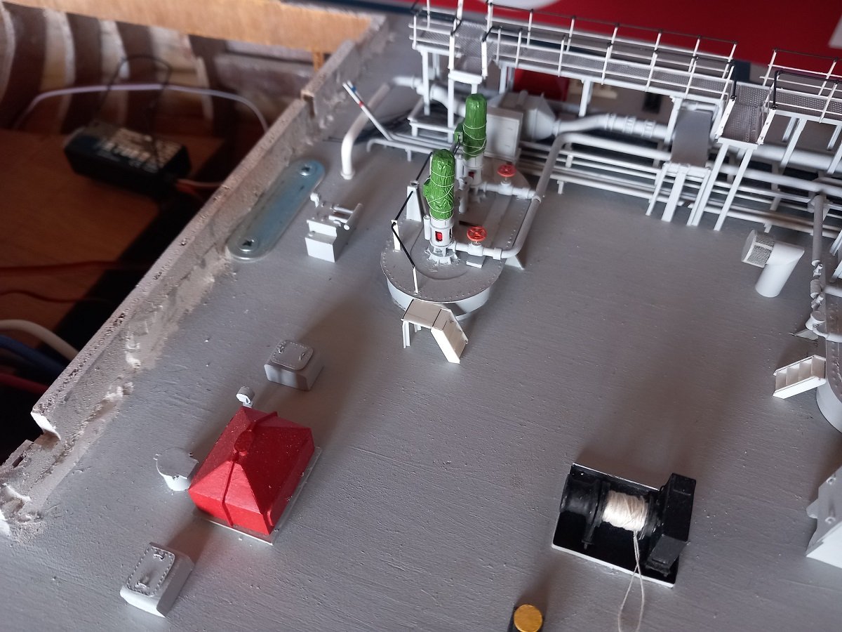
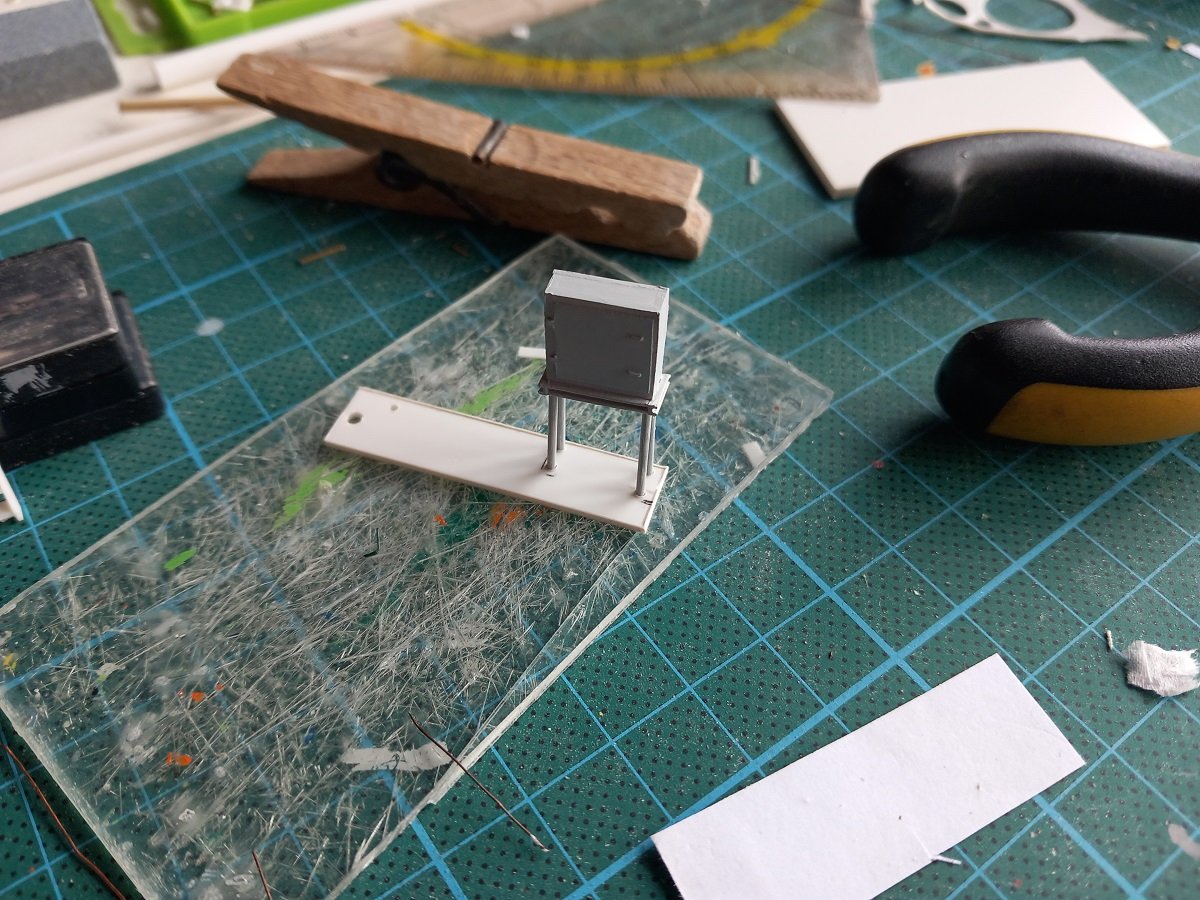
After my little foray in the SIB theme, it's time to get back to this one. I had a few options, I guess I want for the most logical one and that is going forward from where I left off. So this is the area I'll be concentrating on for now. A cardboard template of the catwalk in that area is fitted to check out for size and fitting. Slight adjustments are required to let each part fit. However first I'll need to do that details on the lower levels inside the catwalk area. I'll probably destroy that catwalk if I'd put it on first. So you can see that white, unpainted structure with stair, that's one of the pieces that still needed to be made. That set me off on a whole series of small stairs. Basically each tank dome has a small 4-step stair to the main deck, so I started making all those first. This jig is about as old as the model itself, not perfect, but still good enough. It also allows to adjust angles for the different stairs etc. And the first ones are there. The one connected to the platform is a bit too flat, the angle isn't correct, so I'll change it by a steeper one. And the additional details required on the tank dome are the instrumentation box, cabling between the two pumps (similar to the aft tank dome) and the handrail. For the instrumentation box I needed to make the legs. To get it firmly on that deck, the legs are drilled into the deck before gluing. First I made a template based on the box bottom itself. I drilled 4 holes to fit the corners of the box. I then used that template to drill the holes in the deck. I then cut the legs to length, glued them to the box and used the template again to get them straight, so they'll fit in the holes in the deck later on. So here you see the glued legs to the box in the template. Hopefully it'll fit nicely in the deck now.

-
That's not a very true assumption, rope rarely, depending on the lay of it, has a tendency to coil up round. It generally depends on the lay, direction of coiling and simply the motion that is made during coiling that would define the shape of it. I must admit this is looking more like a coil that was made vertically, hanging and then laid down afterwards rather than a coil that was made straight on deck. But honestly... if that's the only question we can pose, he's doing a great job. And that's what this is! Great work all around, astonishing work and VERY Tiny blocks indeed!
- 2,699 replies
-
- 4
-
-
-
- heller
- soleil royal
- (and 9 more)
-
HNLMS Jacob Van Heemskerck postcard
Javelin replied to Ferrus Manus's topic in Nautical/Naval History
Not sure if this will work, but plenty of plans of that ship on the Dutch national archives. Jacob Van Heemskerck -
I think I'll make a half-hearted attempt at 4 frames of a ship and then go to Glen in despair and ask him to finish it for me 😁. I know, the starting point here was by no means half hearted, but if Glen can do it better, why make the effort...😆. Joking aside, regardsless of some historical accuracy issues (perhaps), you're doing a marvellous job here!
- 301 replies
-
- 6
-
-
-
- Constitution
- Bluejacket Shipcrafters
- (and 1 more)
-
I kind of regret you're finished. She was a pleasure to follow and came out beautiful! Love the way you did the sails, brings an extra dimension to the build. I'm sure you learned a lot of things and will use those lessons in the next build.
-
Neverland Hobby - is this a legit model manufacturer?
Javelin replied to bruce d's topic in Plastic model kits
Seems indeed the shop in Bruges (not Brussels, very insulting for Bruges 😋), is called Hobby Neverland, while the manufacturer is Neverland Hobby.... -
Neverland Hobby - is this a legit model manufacturer?
Javelin replied to bruce d's topic in Plastic model kits
You are talking about a shop near Bruges. I've been there in the past. It's a shop, as far as I know they don't produce anything and are therefore different from the manufacturer Bruce is enquiring about. -
I saw most of your updates by the posting on the main page, but seem to have missed quite something now. Finally following this topic, better late than never I guess. Great job on Lula, she looks very realistic. Having some gaps left and right is good in this case. She was pre industrial mass-production and therefore likely to be less sharp and crisp as anything built later on. Hope you didn't get hurt too bad from that fall...
- 732 replies
-
- 6
-
-
-
- Lula
- sternwheeler
- (and 1 more)
-
That's a brilliant stand! Never seen this before, so quite original and beautifully executed. (the ship as well)
-
Although I don't have stands for my models, I'd look for supports for curtain rails of the rod type? Old brass versions of those. Perhaps modify them a bit.
-
YES PLEASE! A dredger would be fantastic! However, first Lula. A gorgeous piece of work and a great example of combining materials to reach an overall complicated appearance! True scratchbuilding. I can't imagine, but do hope, to be building such sharp and intricate details at your age.
- 732 replies
-
- 7
-
-
-
- Lula
- sternwheeler
- (and 1 more)