


Javelin
-
Posts
632 -
Joined
-
Last visited
Content Type
Profiles
Forums
Gallery
Events
Everything posted by Javelin
-
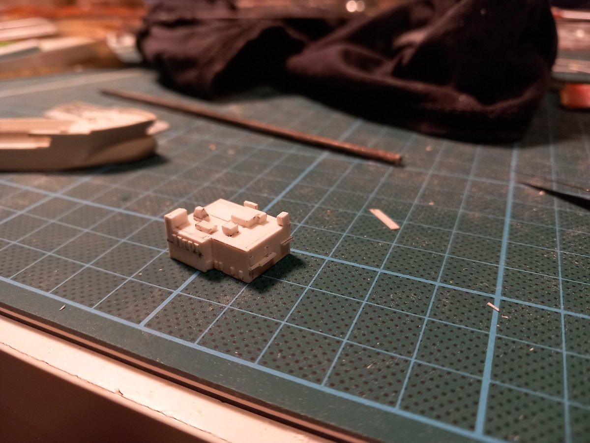
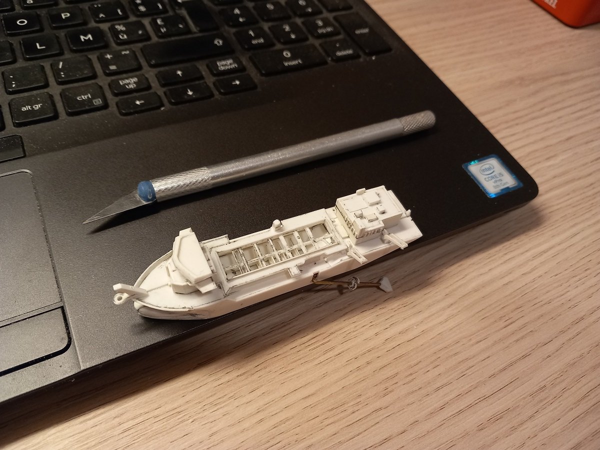
 Yes they did, it's called a Cutter Suction Dredger: it walks on the spuds, at the same time it eats by cutting and dredging and it poops by discharging the dredge waste through the floating line at the stern! So we'll call them "dredging cows" now. @Keith Black, Haven't tried the varnish trick yet, but that might help. Time fore another experiment I guess. I did however prime the surfaces before with spray primer, also that didn't work... As for the cloud, I made a set-up today to see where we are and I'm not that unhappy with that cloud. Mind you I remeasured the bottle with the sand bottom in today. It gave me much less space than anticipated, but this set-up with the eraser below the hull is pretty accurate in dimensions. Still a lot of work to do though. I've been aching to start painting it, but since there is still a lot of detailing to do, I decided to continue building first. It's also freezing outside, so spray primer isn't a good plan for the time being. As you can see, she has also received the propulsion tunnels, I think I'll leave them empty. A propeller is possible, but nobody will ever notice, certainly not when I mount the rudders behind it. First I'll paint the dredge pipe, then mount it, close the hull and paint the hull. Once that's done I'll continue on the deck. I believe turning the gantry is possible, but to keep it in place is still a question mark. And for size
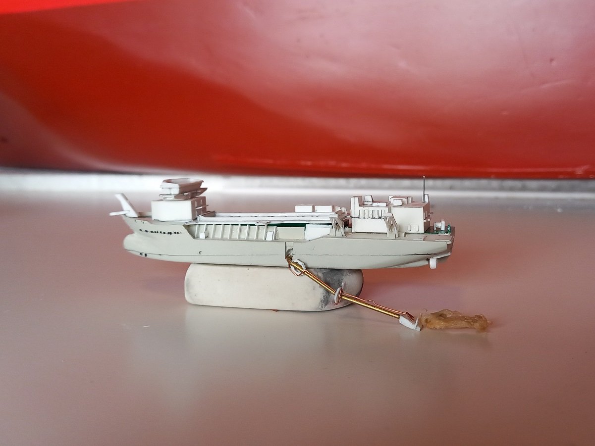

- 70 replies
-
- 9
-

-
- Scheldt River
- Dredger
- (and 2 more)
-
Well basically what Glen was saying, it should represent a cloud of sediment being stirred up behind the draghead. Good you think it's fluffy, cause it's not... By immersing it in epoxy it collapses like a wet rag, but by stretching and shaping it during curing, it gets hard in that shape. That means it won't collapse when I pour the resin later on. I plan to glue it to the draghead before insertion. I'll make a test to see if I like it. The lighter shade might make it more visible I guess. Unfortunately that can't be done. In reality it's either dredging or discharging. The rainbowing is done stationary and dredging can't be done stationary... You did make me think about a rainbow from the bottle cap though 🤪 As for the gantry thing, I might try to rotate it 90° backwards together with its base and rotate it back sideways when the hull is inside. Will need to check if this is physically possible though, it's kind of tiny and I don't want it to fall off inside that bottle.
- 70 replies
-
- 3
-
-
- Scheldt River
- Dredger
- (and 2 more)
-
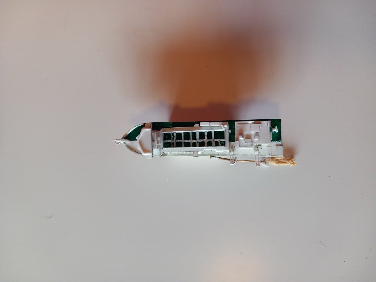
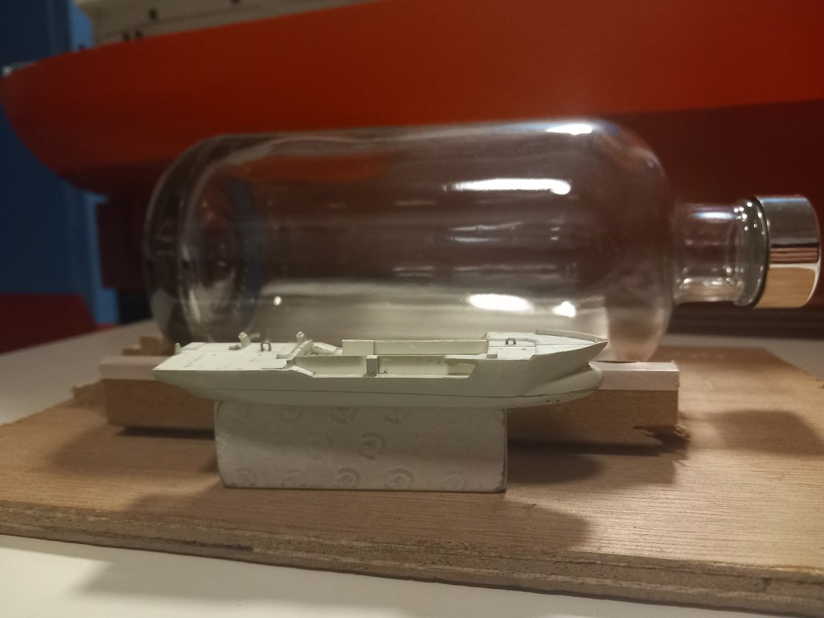
Thanks Glen, but then you do build 3 or 4 ships by the time I start 1... Not a great amount of work done. Mostly detailing and preparing for paint now. First half will fit, not too much space for anything extra though. Although it exactly matches the drawings in size, it does appear larger than I expected by looking at that paper template... On the brighter side, that does mean more color in that bottle and she will catch more attention that way. But then it's also time to get an idea of the size of the elephant in the room... Taking off a bit of length of that gantry isn't going to solve it... Moving it lower or higher doesn't solve it either. Only when lowered to extreme and unusable height, it will fit through. Guess that planning wasn't too good after all. The point is of course that the drawings I have are not with the deployed dredge pipe, so they don't show the gantries when extended. The forward, shorter one, does fit without a problem. So I'd only need to solve the aft one. As you can also see, I've been putting some moss green paint on it. Still a crappy paint. I hate to use it, but it'll have to do. Another 10 layers to go before it finally covers I guess. Tried about everything with that paint to make it cover, nothing works. Diluted with water, airbrushed, brushed by hand, always the same result. The pigment clogs together and the paint doesn't cover. Even the parts without pigment have a tendency to leave a surface uncovered. In the lower left corner you see that brownish fluffy thing. That's the epoxied cotton wool. Not very sharp, but do you think I should add it behind that draghead on the bottom or better to leave it out (or make something new)? In the meanwhile I'm also completing that dredge pipe. I'll need to install it in the hull in order to finally close that hull and paint it. There's going to be some extra detailing on that head as well.
- 70 replies
-
- 6
-
-
- Scheldt River
- Dredger
- (and 2 more)
-
It's not the radioactive resin from AK, but the dark earth... That's the reason I was asking about that before. I've been mixing acrylic with sand to create bottoms in the past and then poured epoxy over it. On 2 occasions it started making bubbles very late in the curing process, which then got those bubbles stuck inside the epoxy due to the low viscosity of the curing resin. I believe acrylic gel reacts with epoxy. In my latest attempt I'm mixing sand with epoxy to pour the bottom, this also would get any air bubbles between the sand grains stuck inside that epoxy layer when hardened. High temperature/sun affects epoxy curing, but it's not something that starts it. Too hot and the thing will start to go really bad, too cold and the chain reaction of the two components will slow down and stop. It cures by a chemical reaction, that reaction creates heat, which then creates a good temperature for the surrounding molecules to react. When that heat is taken away by the surrounding environment which is too cold, it stops that reaction. If it's too hot around it, the reaction will go really fast, so the heat created by the reaction itself can not get away and builds up till very hot temperatures, creating a boiling effect. To get a proper curing you need the good quantities of the components (weight wise), properly mixed and be in the good temperature range. Another thing you need to check is whether the epoxy is suitable for the thickness you're trying to pour, again related to getting rid of the exothermic heat by having enough contact with the environment. However, considering it didn't harden only on that contact surface, I guess it did react to the acrylic. On the other side, the heat you encountered might be caused by overheating in the sun and perhaps melting something on that contact surface with the bottom? It's also an area far away from any contact with the environment in all directions, so perhaps it couldn't release the heat? Not sure how to solve that though... Is the upper part contact surface still really liquid? Or is there some kind of reaction going on? Opening it up might have helped to get rid of the heat and let the curing proceed. Fingers crossed!
-
That black is indeed very unforgiving, but your result looks very professional. I love the contrast between those wood fenders and black hull. Great choice of colours!
-
It looks Brilliant Keith, a work of tremendous patience!
-
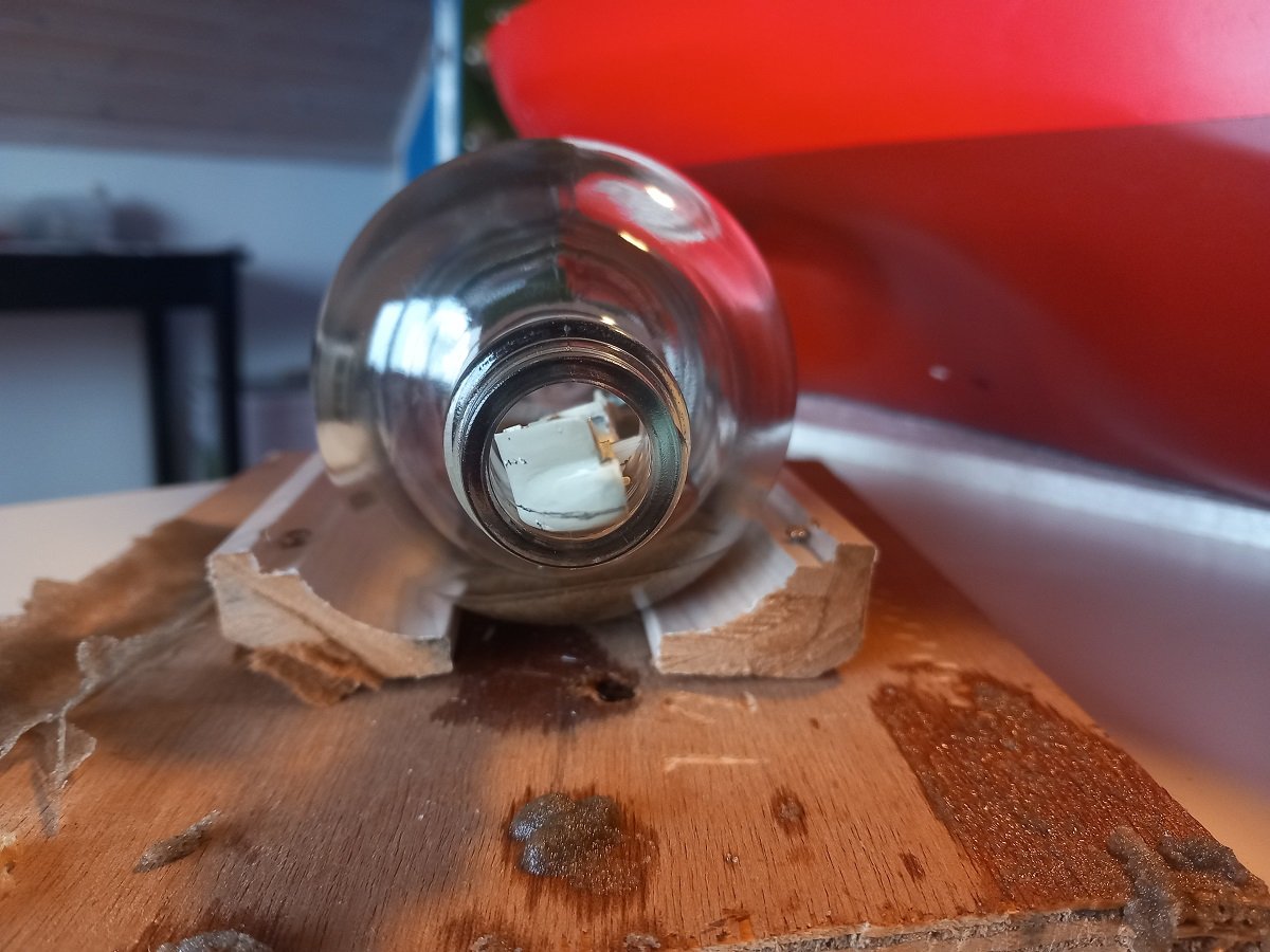
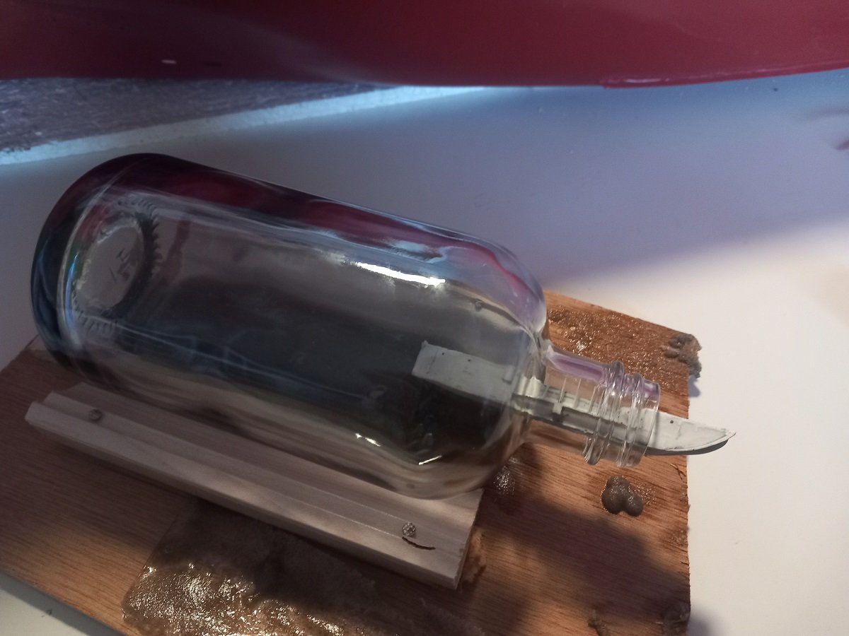
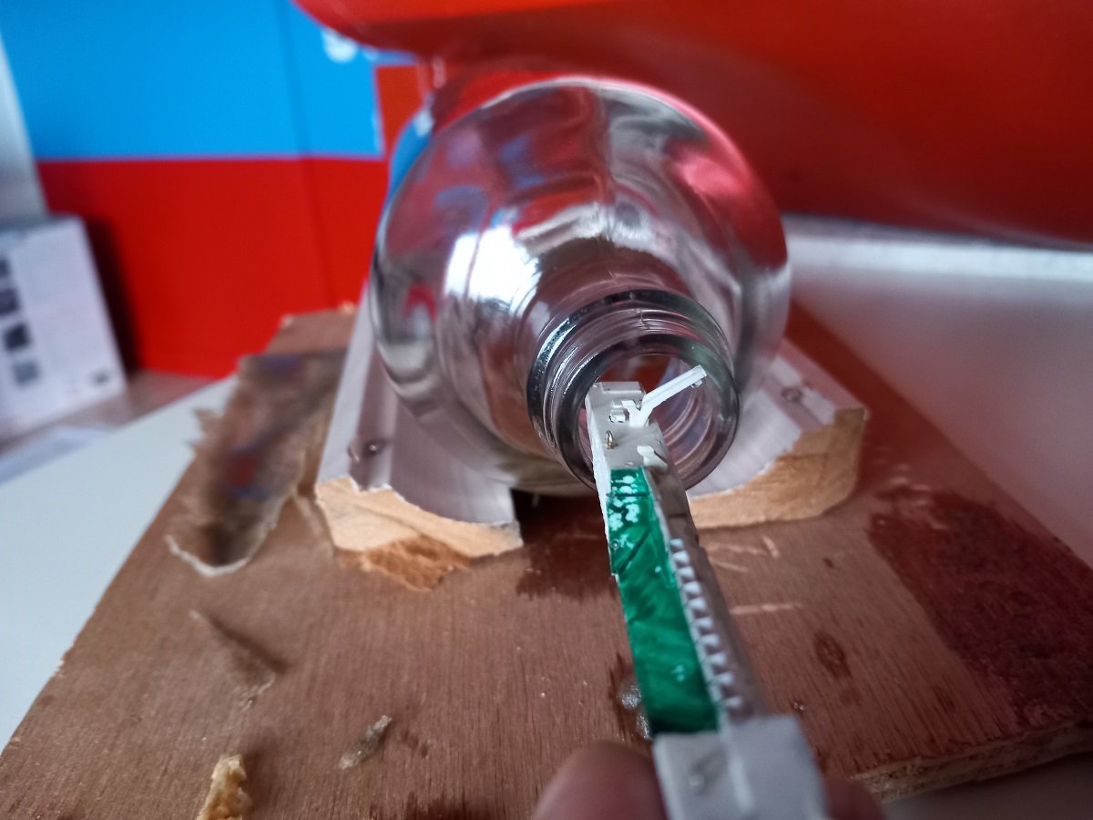
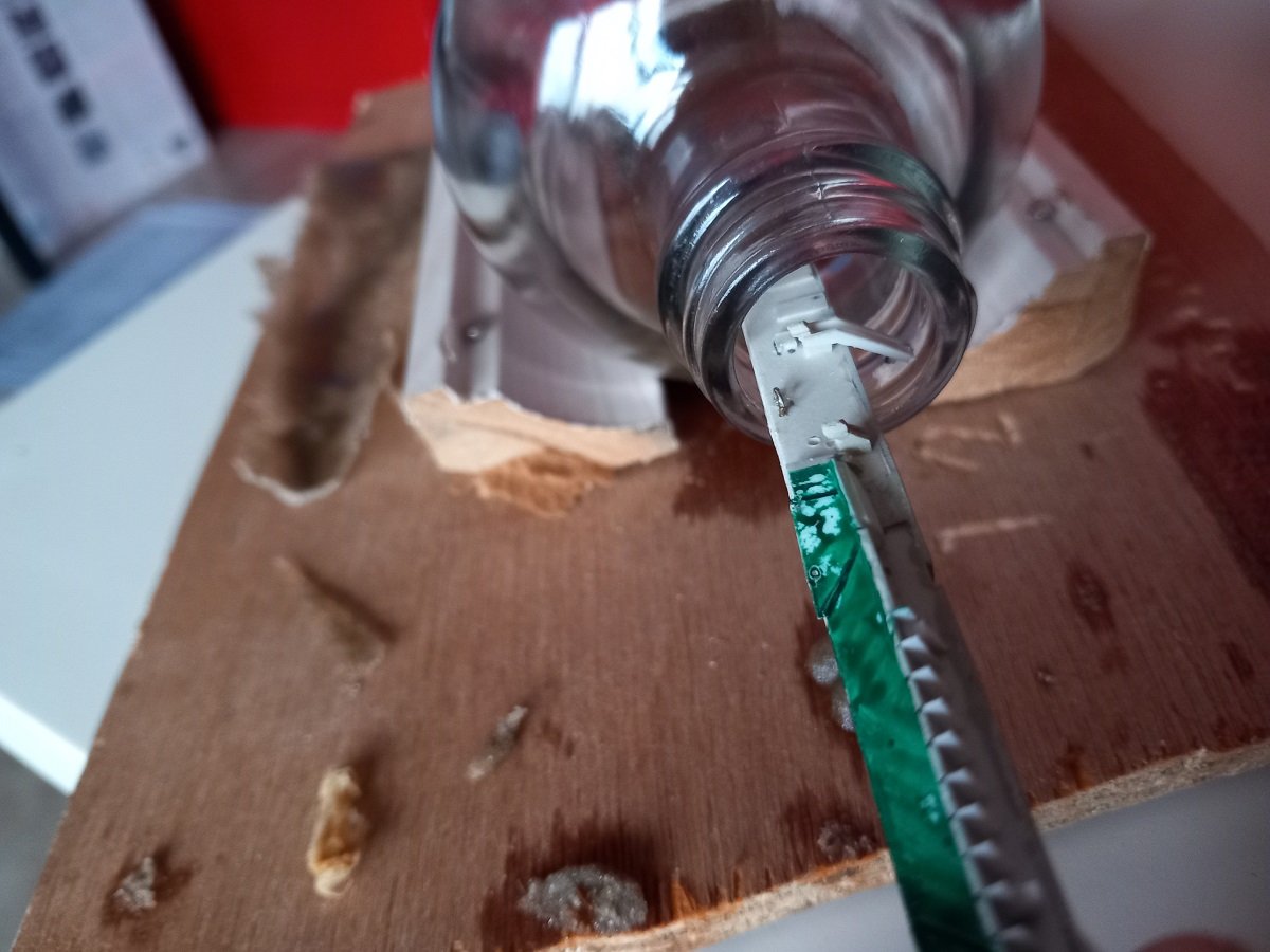
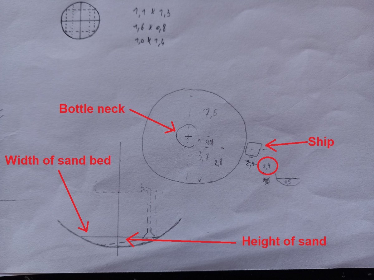
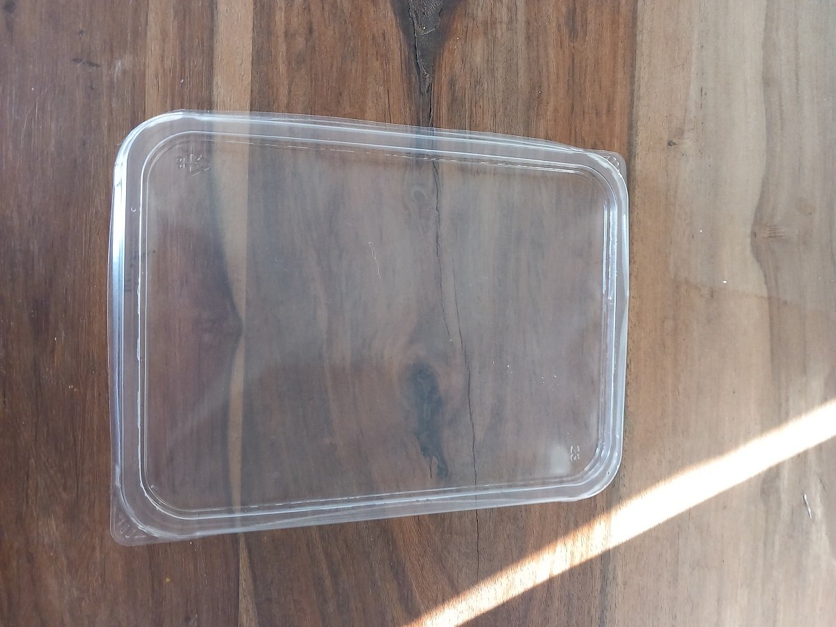
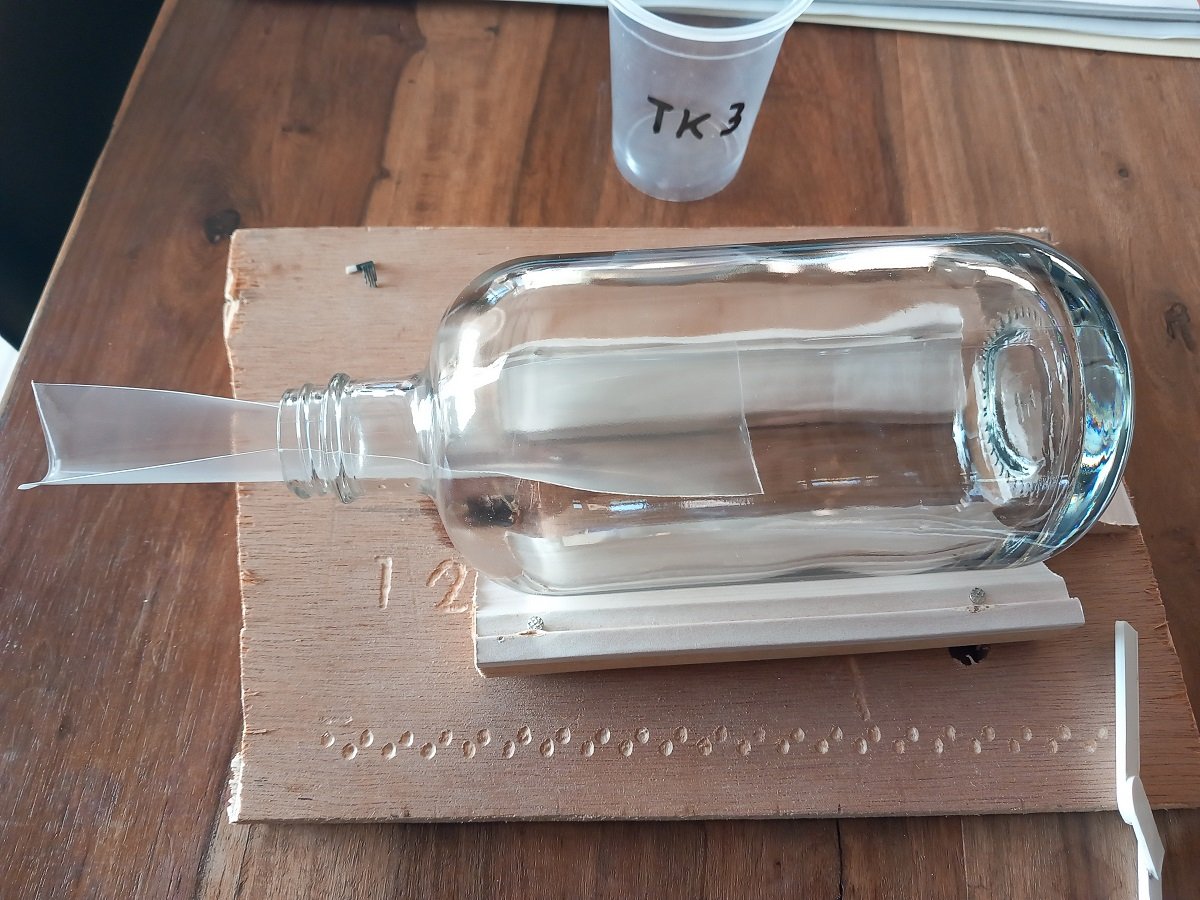
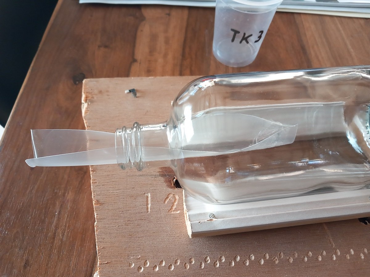
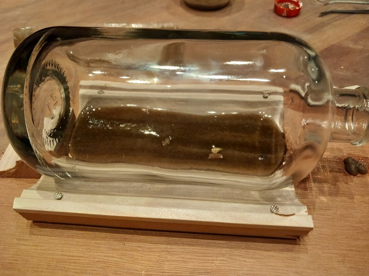
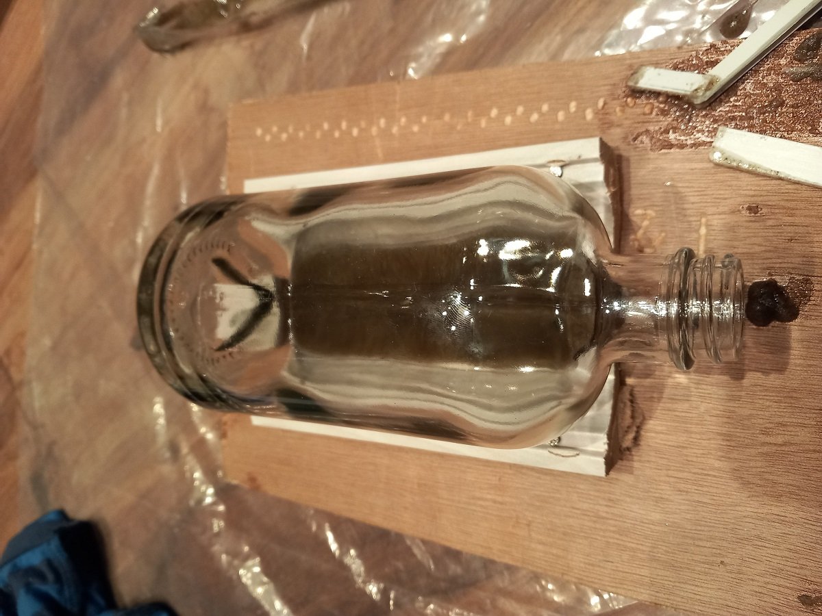
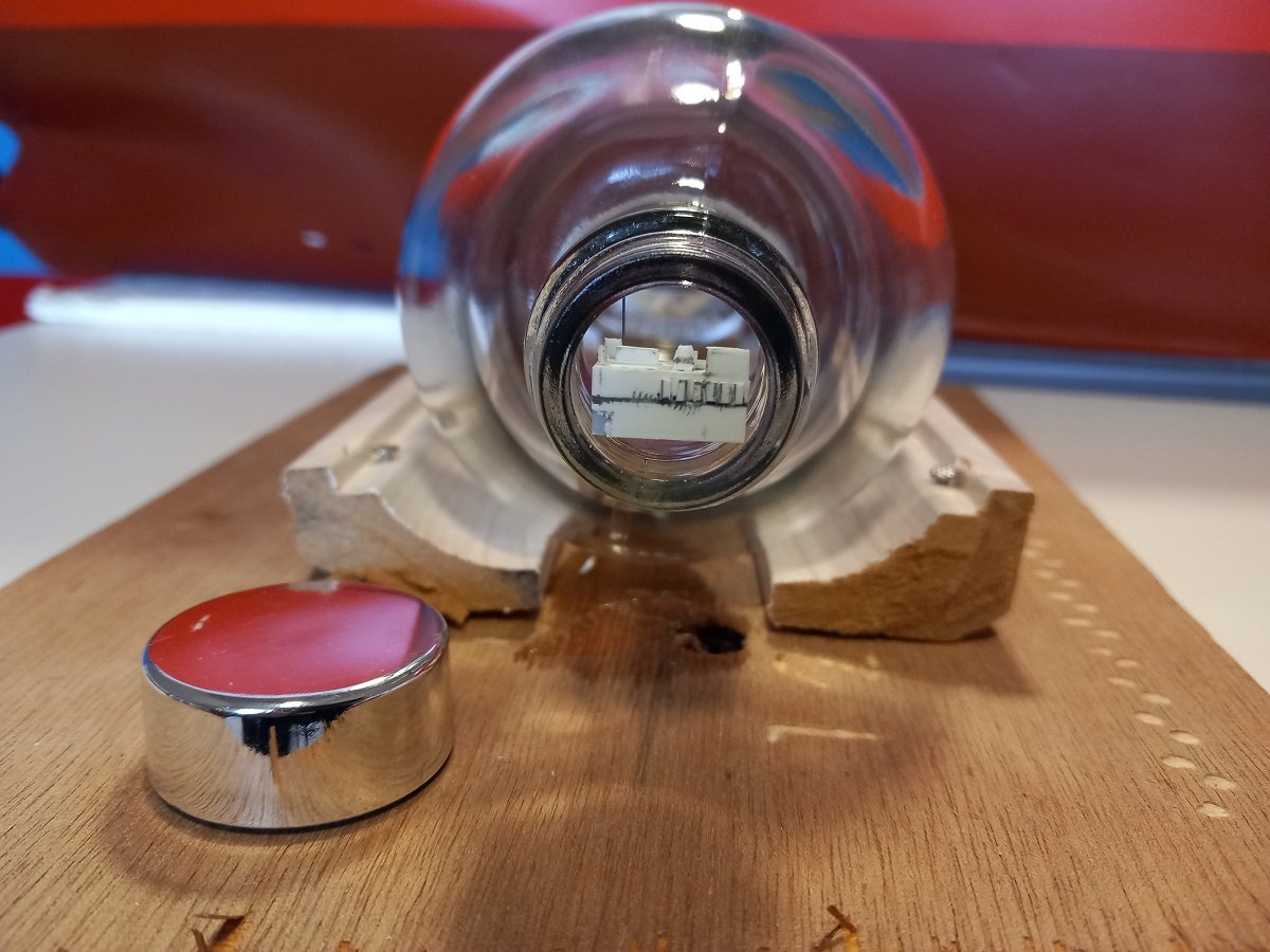
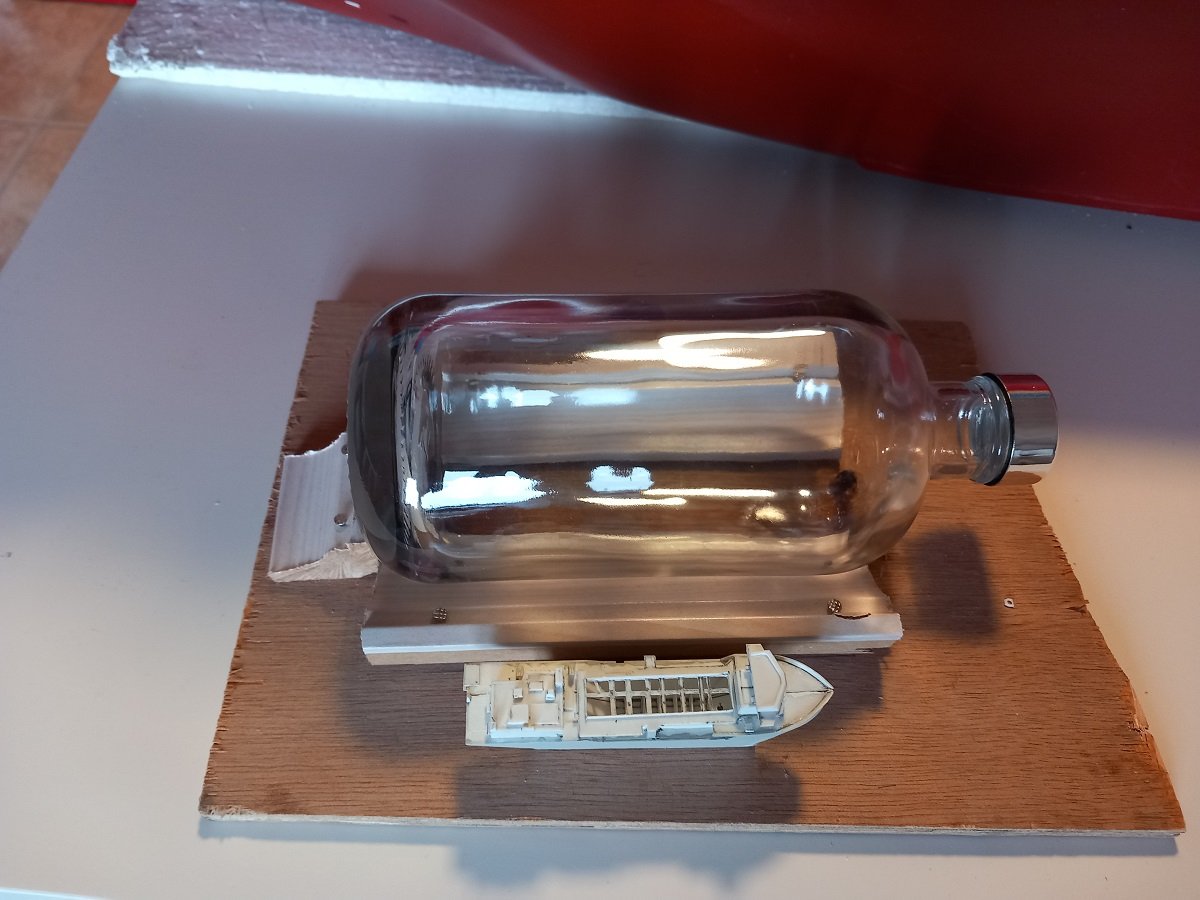
Hi @Glen McGuire, The pictures are a bit misleading as part of the bottle is inside its stand and the ship is not pictured at the height that it will sit at. She has a rather shallow draft, even when fully loaded. This was of course intentional to allow her to dredge in shallow areas. I've taken your concern in account a long while back. I made a drawing to be able to calculate how much clearance there would be. I started by drawing part of a circle (lower left part of the drawing) with the radius of the bottle (unfortunately I did this onboard, using the inside of the previous bottle as I didn't know the real bottle radius). Then I drew the width of the sand bed that I required. From this I could measure the height of the sand bed. Then I want to the top part of the drawing, where I have a frontal view of the bottle, with the bottle neck pictured. I then inserted the measurements, including the "ship" next to it with its perceived draft. This way I could calculate the "Under Keel Clearance" (an actual and important maritime term). I ended with 2.4cm UKC (nearly 1"), which isn't much, but one can not get much more out of this I'm afraid. The only other way would be to have a "Amaretto" or similar rectangular bottle, but those are difficult to find in clear glass. Now I did measure the real bottle inside, it's slightly over 7cm, which means only a couple of millimeters from my drawing. The picture above with her "dredging along the edge of the laptop" is more or less what it should be. Due to you bringing up this topic, I pulled myself together and in a short period of free time I actually made the sand bed in the bottle. Last time I had a lot of issues getting that sand through a piece of pipe, so I needed to improve on that. I used a plastic lid. Cut it to size and inserted it in the neck, this way I could avoid dirtying the neck too much and due to the transparent plastic I could actually see what I was doing with the sand. Now I didn't like the end of the guide inside the bottle as this would make a mess when retracting it afterwards. I then taped that end together with some cellophane tape. I then put some sand inside the guided and pushed it inside the bottle. Later on the in process I drew the guide back in order to spread the sand more forward until I reached the end. This time I used an epoxy with sand mixture instead of acrylic gel with sand. This is to try to avoid that bubble issue I had with Spartacus and Sea Installer. I then curled the guide together so the dirty edge wouldn't touch the neck. I then flattened the sand a bit with some of my previously self-made tools. I also added some stones and when it was gelling, I tried to make a trench where the draghead will pass along the bottom. There is also something that represents ribs from a shipwreck near the neck. Tiny of course, I'll try to picture it better later on. Now since you brought up the level issue, I actually thought the sea bottom isn't always level, so part of the solution to the height and visibility issue is rotating the bottle slightly. (in the top drawing you see a dashed on the lower left drawing), this brought the sand bed more to the side of draghead while reducing the width of the sand bed (and height below the hull). However, when making calculations I had to take some extra to account for losses and I couldn't believe the small amount needed... In the end I put way too much sand inside the bottle. I'll remeasure the clearance once it's hardened. Here you can see, I used the seam of the bottle as a top mark, it's slightly rotated in its stand while I made the sand, so once hardened, I'll rotate the seam upwards. Even with too much sand, it should increase visibility slightly. I also tried to make an epoxy cloud to drag behind the drag head with cotton wool, but it doesn't look very promising.
- 70 replies
-
- 5
-
-
- Scheldt River
- Dredger
- (and 2 more)
-
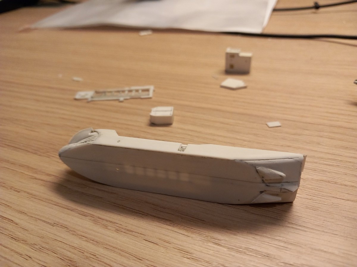
Thanks Keith, And a (belated) Merry Christmass and (future) Happy New Year to you all. May you all celebrate these days with friends and/or family and enjoy the moment! As for the model... Well, I did succeed in doing something on it since arriving home, but not much. With Christmas etc. it's entirely stopped, we'll see for how long. In any case, at home I did have the full array of tweezers etc. available, so I did some further detailing on the superstructures. At the same time, I applied Milliput epoxy filler to the bow and stern areas to make the transition between several pieces of styrene a bit more smooth and to get a better seam between the two halves. I'm not entirely happy with the seam, but I've done to attempts now and I guess it'll have to stay like it is. For future builds (if any) I'll definitely make a flat plate on both ends of the joint and build the hull around that. In this case, by cutting that hopper in 2, this method was not practical. Being home also gave me access to the real bottle in order to test fit a few things. One of the unknown items was the support of the aft crane. It's located near the outside and sticks out quite a bit, which meant it could have caused an issue in the bottleneck. I'm now happy to have it fit, making it easier to mount the crane afterwards. I also discovered that the aft, longest gantry for the dredge pipe is sticking out a bit too much and won't fit in the bottleneck, I still need to think of a solution for that. And here is the hull next to the bottle. She will nicely fill the bottle, perhaps a bit too much. This is after application of spray putty, I will sand it smooth before putting any paint on. Before I do that, I'll first need to install more details on the aft, including prop tunnels and rudders. The anti-fouling line is drawn, it's not parallel to the keel, since these ships are very heavily trimmed on the stern when empty and apparently they decided to apply this trim to the anti-fouling as well. I've also tested the top deck over the hopper and my earlier idea was correct. The platform on the port sticks out too much and it won't fit in the bottle this way. The idea is now to clip that part off and fix it to the hull half. It'll then also act as a good guide to get that deck properly aligned. That's it for the time being, not sure when the next update will come, nor what it will show...
- 70 replies
-
- 7
-
-
- Scheldt River
- Dredger
- (and 2 more)
-
Looks great indeed. What did you make the sludge from? Acrylic? or sand mixed with epoxy? The effect is in any case convincing! 👍
-
So I go out on a day trip and then there's THIS?! Fantastic result Glen, I had my doubts about raising those masts with the ships being loose, but you sure aced that! When it comes to composition, I'm not sure... Your last pic looks good, but perhaps get the Dutchman a bit closer and parallel to Pearl? Once again, congratulations with your work!
- 185 replies
-
- 6
-
-

-
- Flying Dutchman
- Black pearl
- (and 2 more)
-
Congratulations on this excellent piece of work/art. Hard to believe you made this from a kit!
- 158 replies
-
- 1
-
-
- San Felipe
- Panart
- (and 1 more)
-
Spectacular is the correct word for this! I must admit I hadn't expected this to turn out so well, but it truly is extremely close to your reference picture! But now the ships...
- 185 replies
-
- 6
-
-
-
- Flying Dutchman
- Black pearl
- (and 2 more)
-
I've been thinking about this one for a looooong time. The planking looks brilliant and at first I was a big fan of leaving it unpainted. You have no errors to hide. That said, I changed my mind. In an unpainted state, she is not a true model of Cangarda, but rather a different ship. Paint would also hide the contrast with the brass insert for the propeller. If you would leave it unpainted, I guess a mahogany insert in that place would probably look better. Since it would in that case become a "fictional ship", you could put a white line on the waterline to give some contrast. All in all I can still live with leaving it unpainted since that wood looks very handsome, but painted to stick to the original has my preference Not much help in deciding, I know....
-
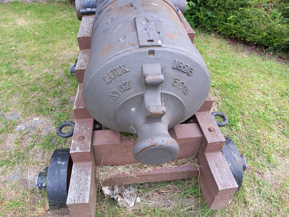
I would indeed say the Maastricht carriage isn't original, considering the trunnion size compared to the capsquare size. The others, I don't know.
-
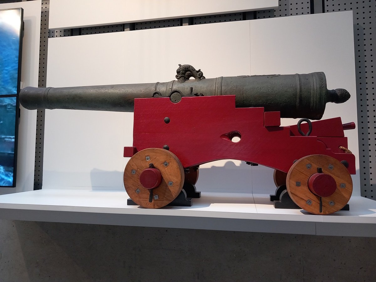
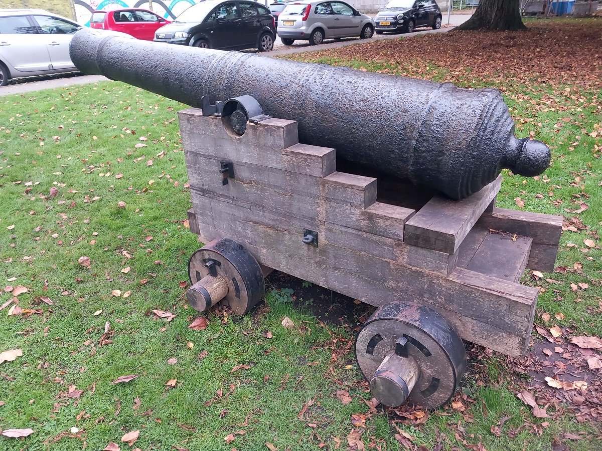
I'd say they're square with the bracket rather than the centerline. At first I thought not, since the use would be for mounting those blocks and you'd want a flat face to touch the flat block face. Then I thought it wouldn't have been necessary when using a quoin? (wedge), but this picture seems to suggest both a block and quoin. (this one is in Rotterdam Maritime Museum). But then I also had these guns: This one is in Maastricht, here you can see the block, but if you look closely at the step below the block and the angles, they aren't straight compared to each other. Looking at the direction of the angle, I'd say the step is square to the bracket, while the block would be square to the centerline. The contact surface on the forward face of the block would also indicate a similar angle, but less visible. And then I have this one, close to my home: It also seems to indicate square to the bracket. I do admit the last ones are not from that age and shore guns rather than maritime ones, but I hope it gives you an indication.
-
Thanks guys. The Dell's ok, but I don't need to use it so much, so I'm not bothered anyway. Small update again. Somehow, because the road was clear, I kept postponing the "hooks" for hanging her in the bottle. Since I'm reaching the end of what I can do, I decided to make them (but without gluing for now). So here they are in place: And here they are already partly covered the way I envisioned it from the outset. I did decide on a single one forward, since the smaller accommodation block didn't leave much space to cover a 4th one. In any case, anything you suspend or hoist is always only supported by 3 legs, so 4th one would be redundant. Once they are glued, I'll make a hanging test with the dredge pipe connected to see how it goes. Additionally I had to drill the stern thruster in the aft skeg between the propellors and also made the shaft/propellor skegs as well. The props are protected by tunnels (don't have the proper diameter rod with me to make those) and of course there are rudders behind them, which would be too fragile to put on for now.
- 70 replies
-
- 6
-
-

-
- Scheldt River
- Dredger
- (and 2 more)
-
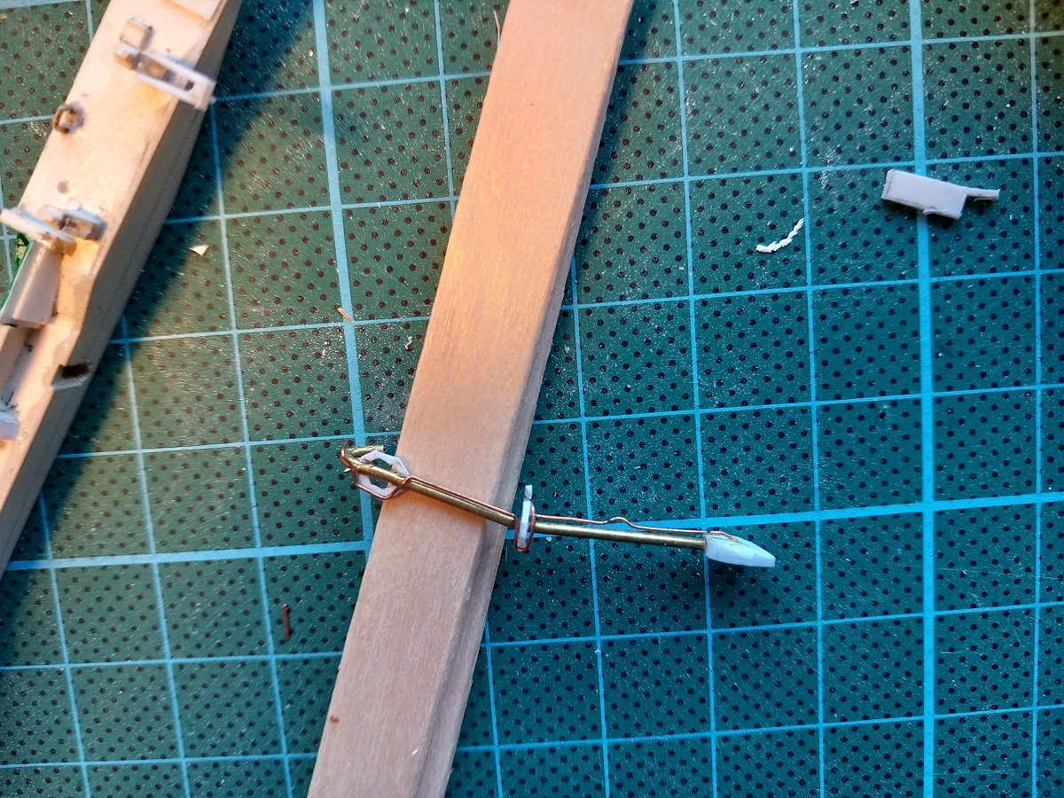
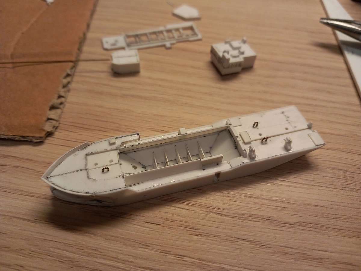
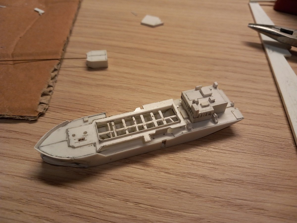
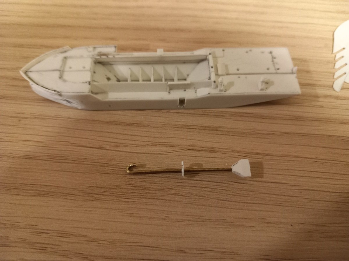
Hi @Keith Black, I'm keeping this one below the radar, most of them don't know. There is a long-standing feud between the TSHD guys and CSD (Cutter Suction Dredger) guys. It originates from the days when CSD's were generally stationary dredgers, only moved from one spot to another with the help of small support craft (much like Lula). In those days the TSHD guys were the civilised people from Maritime Academy, while the CSD guys were short-tempered construction workers. TSHD guys always regarded CSD people as crude retards, while CSD people regarded TSHD people as softies (I'm expressing myself light here)... Nowadays however, with self propelled CSD's, the crew on these CSD's are also recruited from Maritime Academy and/or are industrial/civil engineers that took a maritime education on top of that. That said, there are still some old school people around to keep the feud alive, but the younger people amongst us consider it ridiculous. It does still mean I have to be careful not to be called a traitor on my CSD. So, finally time for the dredge pipe. I was lucky to have the correct diameter or brass rod with me for this one. I've also in the meantime completed some containers and both crane jibs. That means I'm basically finished as far as I can get for now. The dredge pipe will also be detailed a little further with the smaller diameter jet pipe etc. The part in the middle is a swivel part where the lower part of the pipe can bend in and out. Also near the ship's hull there is a piece of flexible pipe to allow the dredge pipe to move transversely. This happens when the suction head reaches a harder piece of soil, where it will automatically slide around by the resistance of the tougher ground or when the dredger makes a turn while dredging. In those cases the dredge pipe will move. They will of course always try to avoid having it going underneath the ship or too far away from the ship. As you can see I made a small hook at the upper end of the dredge pipe, this fits inside the whole I made behind the shell plate (which you can see in one of my previous posts). Once hooked behind the shell, the pipe can move up and down, but stays in place.

- 70 replies
-
- 11
-
-
-
- Scheldt River
- Dredger
- (and 2 more)
-
I guess the smiley doesn't suffice for this build! What a great build. Love the shape, colours and your additional decorations.
-
What a splendid model. I'm with Valeriy on this one, the brass, unpainted parts are a nice touch. Congratulations!
- 128 replies
-
- 2
-
-
- zulu
- sternwheeler
- (and 1 more)
-
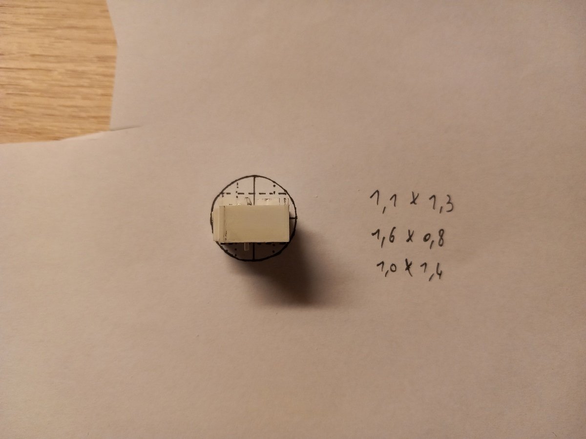
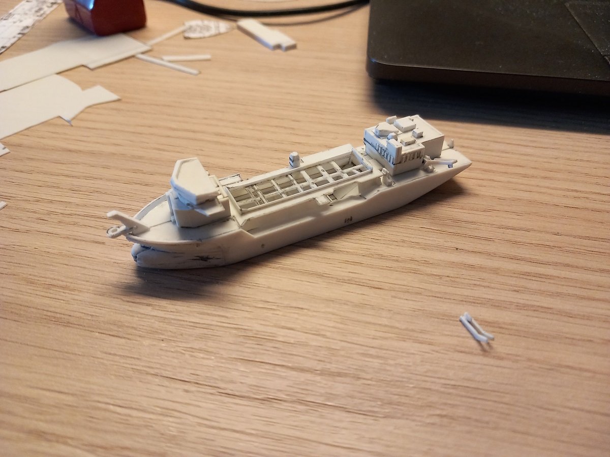
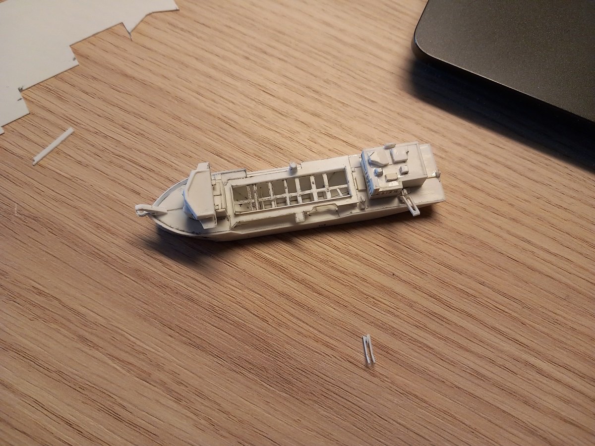
Still plugging away. I believe I might just be about finished with what I can by the time I go back and home and continue this build in earnest. First my actual way of checking whether things will pass or not. As far as I noticed, I will probably need to remove the portside platform from the highest deck, since it makes the deck too wide to pass. However I will only remove once I have checked with the actual bottle. The bottle has a rather short neck, which might allow me to wiggle the complete deck through. The aft superstructure can clearly pass. The numbers on the right are boxes I've drawn in the bottle opening and then measured for easy reference. It makes planning a bit easier. She has now received her bulwark, forward structure for the discharge pipe and the first gantry for the suction pipe. (the second one you can see on the foreground). The forward structure will not be mounted on the deck, since then it won't pass the bottleneck, so it will be attached to the discharge pipe (along with more supports), which in turn will be connected to the main deck and lower part of the superstructure. The bridgewings, bridge and mast will then be a separate part that is placed on top of that. I'll definitely take pictures of the separate parts when I get further in the build. I can only begin to assemble those when I'm painting. If I'm not mistaken I'll end up with 5 main pieces to assemble in the bottle (7 if you count the cranes as well).
- 70 replies
-
- 8
-
-
- Scheldt River
- Dredger
- (and 2 more)
-
Would it be an option to raise the masts opposite? Fix the ship with the masts flipped forward, and use a line to the stern raise the masts?
- 185 replies
-
- 6
-
-
- Flying Dutchman
- Black pearl
- (and 2 more)
-
That's because I didn't use it on my models yet. Pretty sure I'll smash something if I use that railroad track. Funny thing is, it was in the garage when I bought the house. It appeared familiar to me, but couldn't quite identify it until I first saw your piece of railroad track in one of your early logs! As for the orientation, leaving them loose while raising the masts will probably make some damage... On the other side, with your planned orientation, one of the ships will sail away from the bottleneck, so the regular way for raising masts, using the bowsprit will not be possible considering the angle?
- 185 replies
-
- 7
-
-
- Flying Dutchman
- Black pearl
- (and 2 more)
-
Glad you're not giving up on that one. Not sure how that caulk is behaving, but is it an option to brush it smooth rather than adding it in blobs and spreading it? Or coating the surface of the whirlpool with acrylic gel? I'm pretty sure that would leave a very thin, but waterproof layer over it. I'm pretty sure you'll succeed, so I'm already curious how you'll add the ships to it and in which direction?! I love how you build those ships, an inspiration for a future project of mine. Luckily I also have a piece of railroad track!
- 185 replies
-
- 8
-

-
-
- Flying Dutchman
- Black pearl
- (and 2 more)
-
Awesome work Gary, I'm especially amazed by that celophane tape trick. Never seen that before, but the result is astonishing. Love the port holes as well, very sharp execution!