Javelin
-
Posts
632 -
Joined
-
Last visited
Content Type
Profiles
Forums
Gallery
Events
Everything posted by Javelin
-
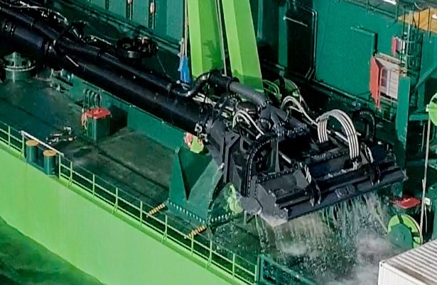
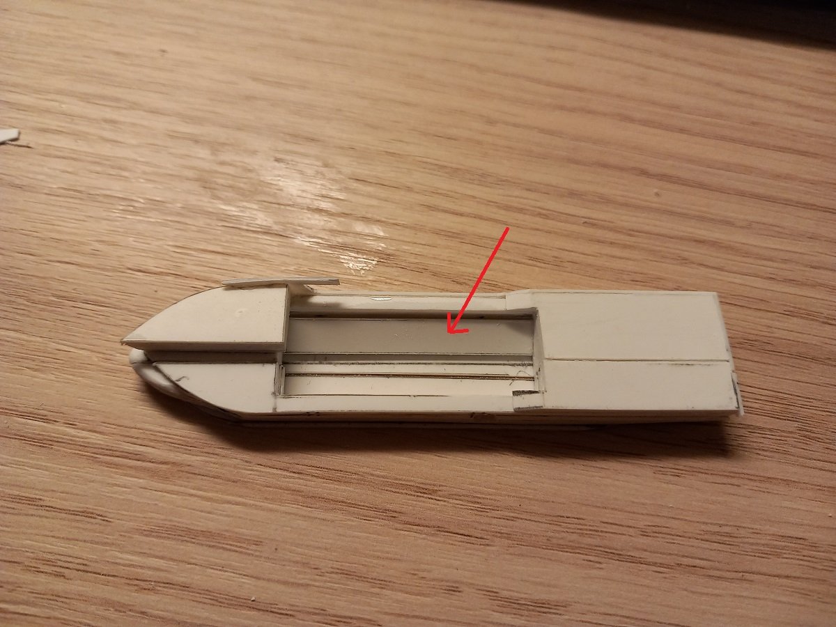
 Before this gets derailed and the dredger has to tow a pod of whales in the bottle, here are some pics of the draghead. Since this is not the type of dredger I work on, I don't have that many reference pictures on this ship. Perhaps that is a blessing rather than a curse, considering the complexity of this ship. As you can see the upstanding parts on both sides could act well to hold the bottle, however the pipe in the centre would leave the forward part of the bottle unsupported, with greater risk of it rolling off. In this shot you can see the row of teeth at the top of the entry. So basically it's a vacuum cleaner nozzle. They adjust the visor, which is the openin/jaw where the teeth are located to create a bigger or smaller opening and it also has these jet nozzles. This type of dredger catches a lot of bombs (depending on the area they are dredging in of course), which then get stuck in the visor. Always a surprise when that head comes back up, occasionally the bombs just fall out once the head is back onboard, but as far as I know, most of the time they are stuck inside. In any case, they have to stop dredging and contact the navy to come and get it out. You'll also be surprised to find out these are generally operated by a single person, the dredging part, putting the pipe overboard etc. is very automated, so he mostly concentrates on navigation once dredging is started. Of course there is a crew onboard for the machinery part as well as the maintenance part of the dredge equipment etc. In some areas with very dense traffic they are obliged to have 2 people on the bridge, one for dredging and one for navigation.
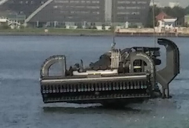
- 70 replies
-
- 7
-

-

-

-
- Scheldt River
- Dredger
- (and 2 more)
-
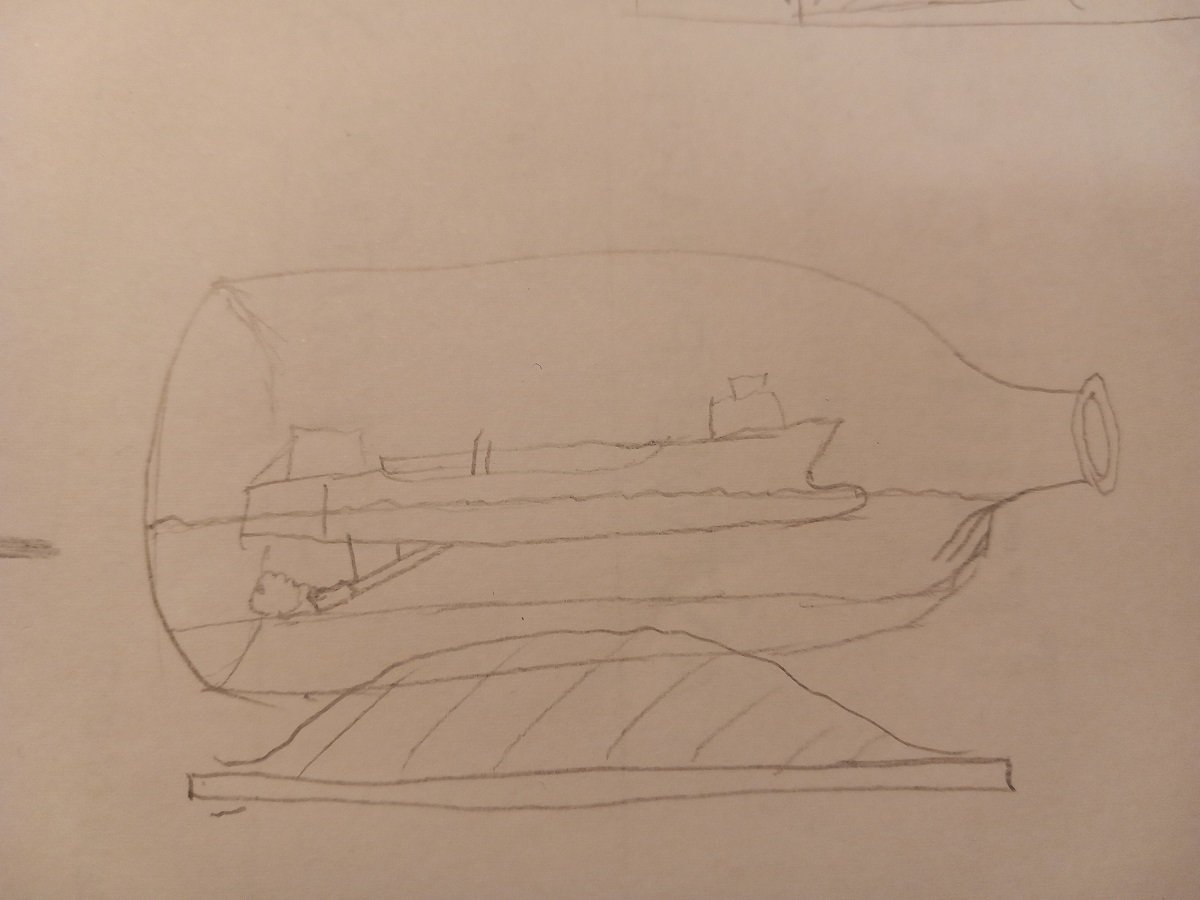
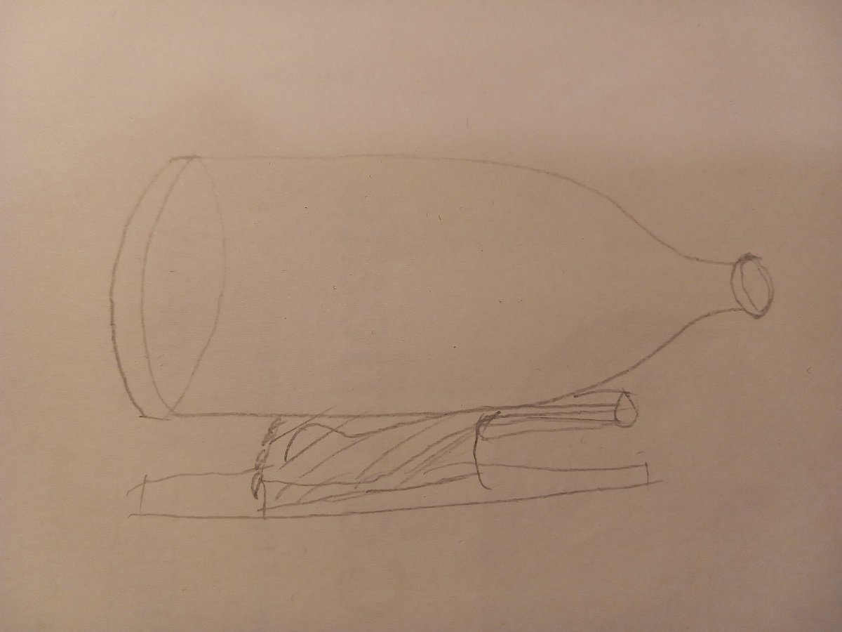
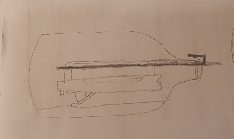
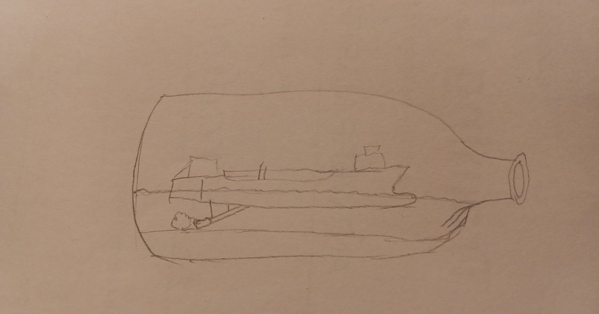
Through the fog it is @Glen McGuire, Without the bottle I'm sort of hoping things will get through the neck... One of the things I hadn't decided on a straight path yet was the mounting of the top deck or at least where and how that seam would run. Part of it will be hidden underneath the forward superstructure, but another part won't. On the starboard side, the dredge pipe runs along the accommodation block to the bow and for structural reasons I decided to make the supports of that pipe and rest them on the deck. I guess I could also leave them hanging, but that would be a risk during entry of the bottle and during installation as there would be no way for me to rectify any of it once it's in the bottle. Here is where we are today, I've finally started with the finer detailing on that aft superstructure. The forward part is generally finished. However the bridge is kept loose as it will otherwise be too hard to paint and put the windows on (black marker, just like the Sea Installer). There is a coaming around the hopper opening now, still need to do the aft edge. The dredge pipe will then be built and connected along this deck, all the way to the bow. With a fairly good view on where this will go and only some detailing/finishing to go, it was also time to think about how to support the bottle. Once again I have two different ideas, the first and most intensive, would be to mount the bottle on top of a draghead (scale and with part of dredge pipe or not still to be determined). And the draghead would then be laying on a sandy base. Sorry for the crappy drawing, I haven't studied the construction of a draghead too well yet. It's tricky since there is no proper support on top of it. The second idea is by far the simplest and is basically a stack of sheets over which I would make a "mountain" of sand in which the bottle lays. I can use my regular acrylic gel-sand mixture, which will stick well to the glass as well. I assume I could even make a third idea by simply sticking sand-acrylic to the bottom of the bottle until I get a flat bottom to prevent the bottle from rolling. I could match that also with the contour of the sand inside the bottle?! In any case, something to think about in the near future. I guess the draghead plan is the least likely, since it will be time consuming and difficult to get the bottle steady on top of such a structure. Apart from a draghead, there are no real pieces of equipment that are typical for a TSHD. A dredge pump is less typical, but perhaps easier to adapt as a stand. Let me know what you guys think?
- 70 replies
-
- 5
-
-
- Scheldt River
- Dredger
- (and 2 more)
-
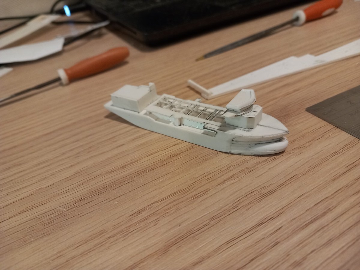
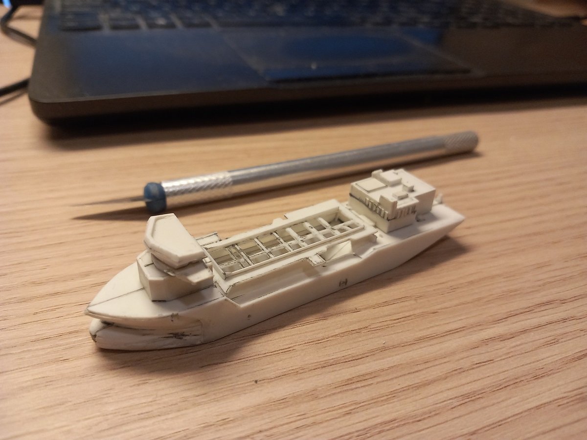
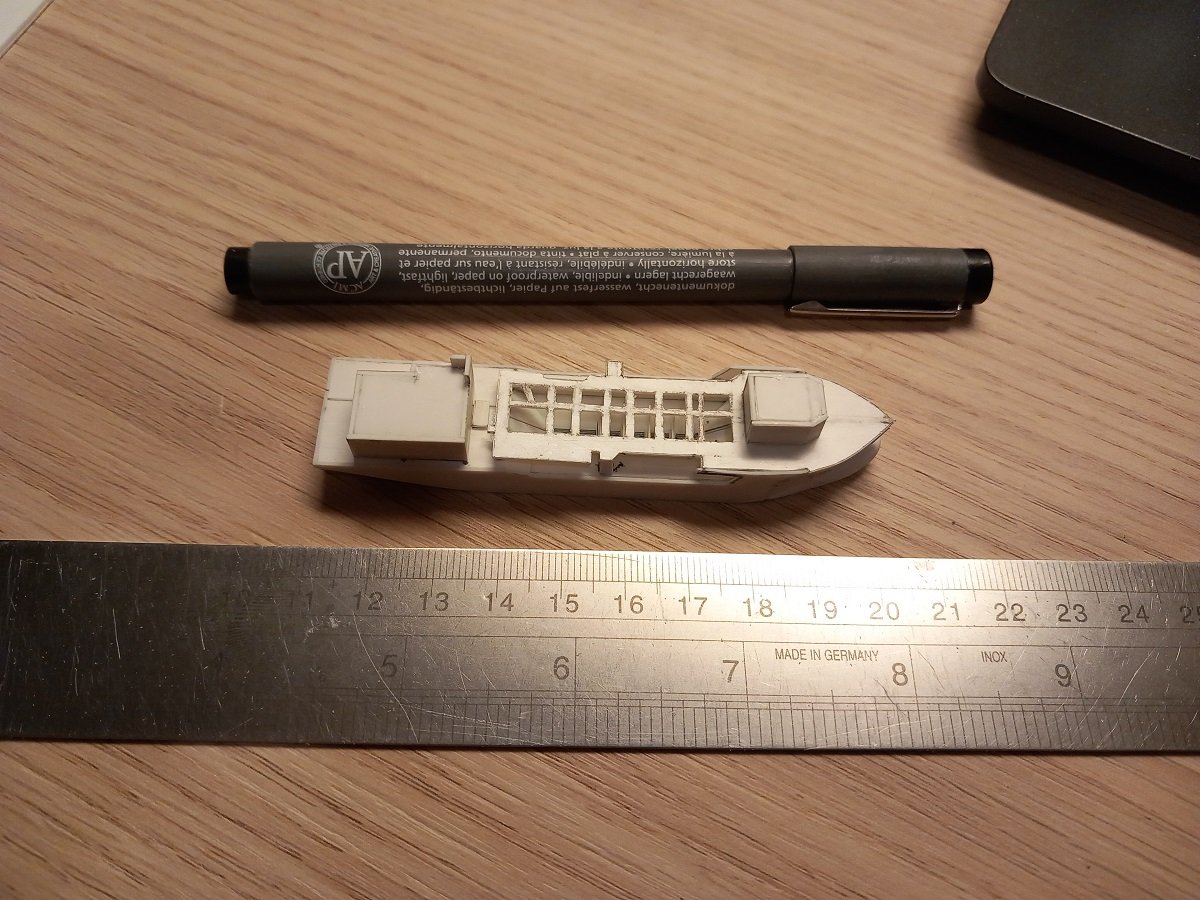
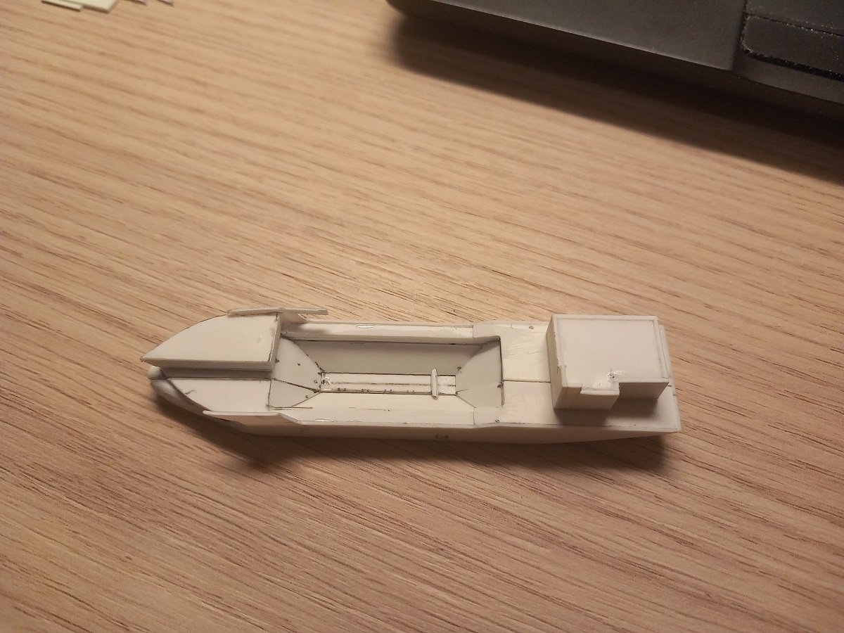
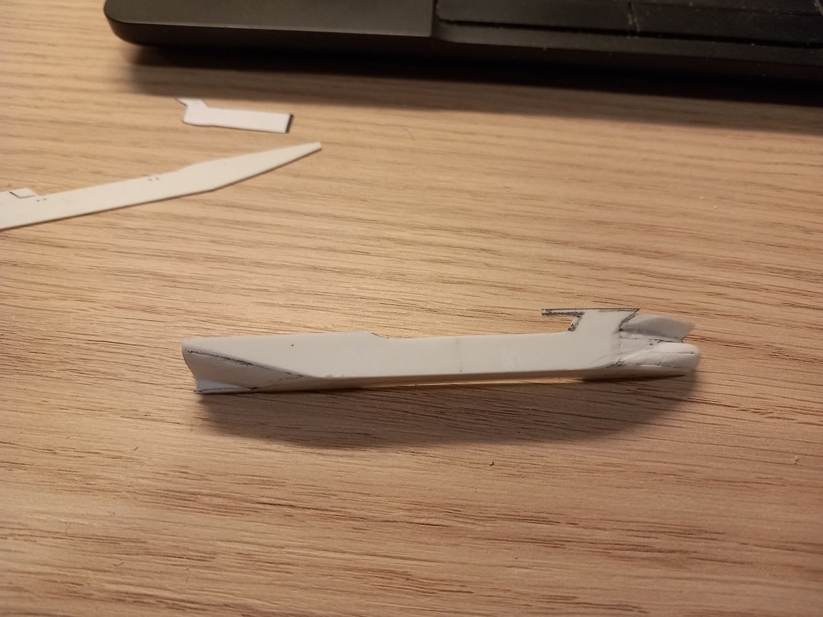
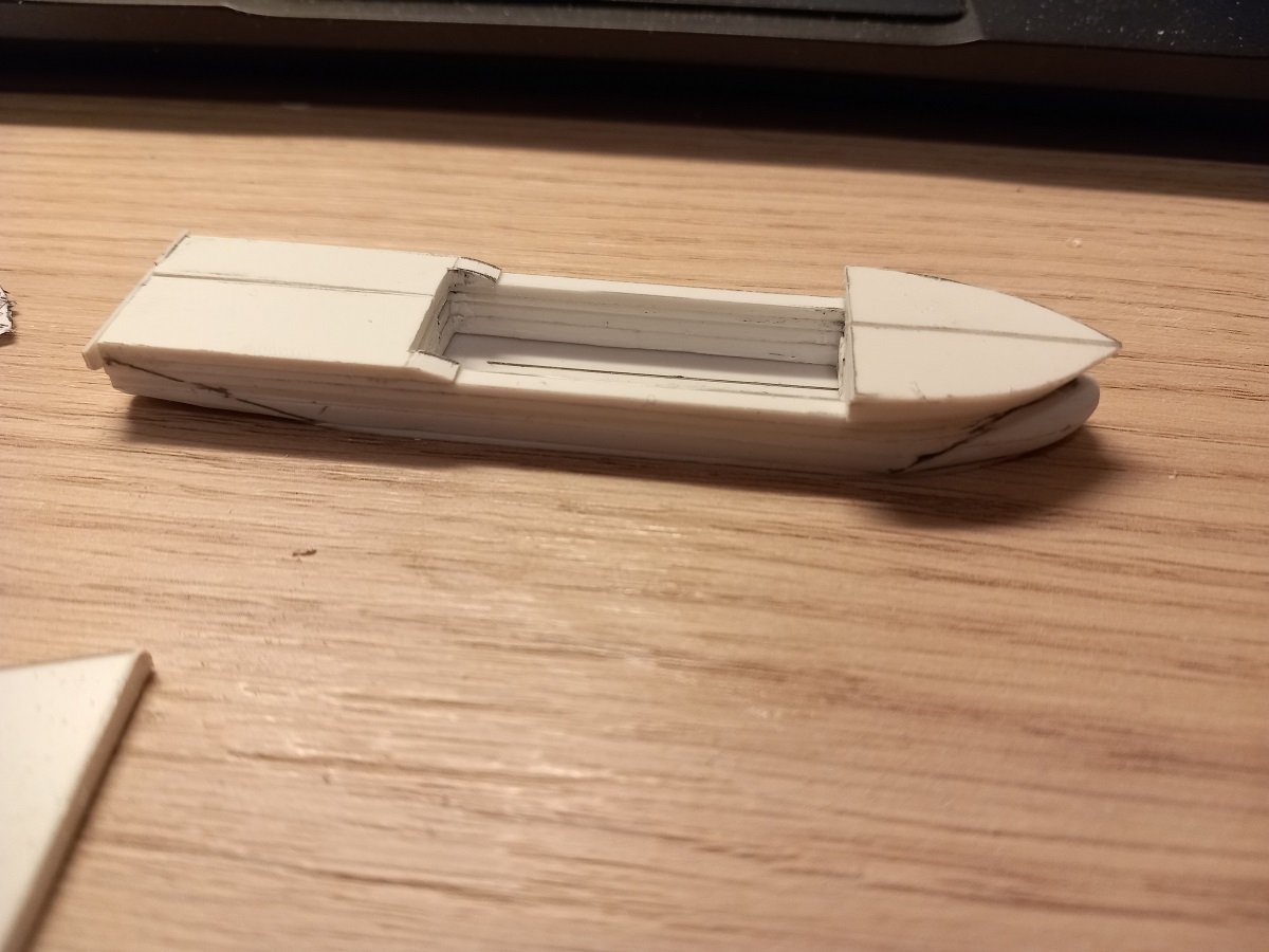
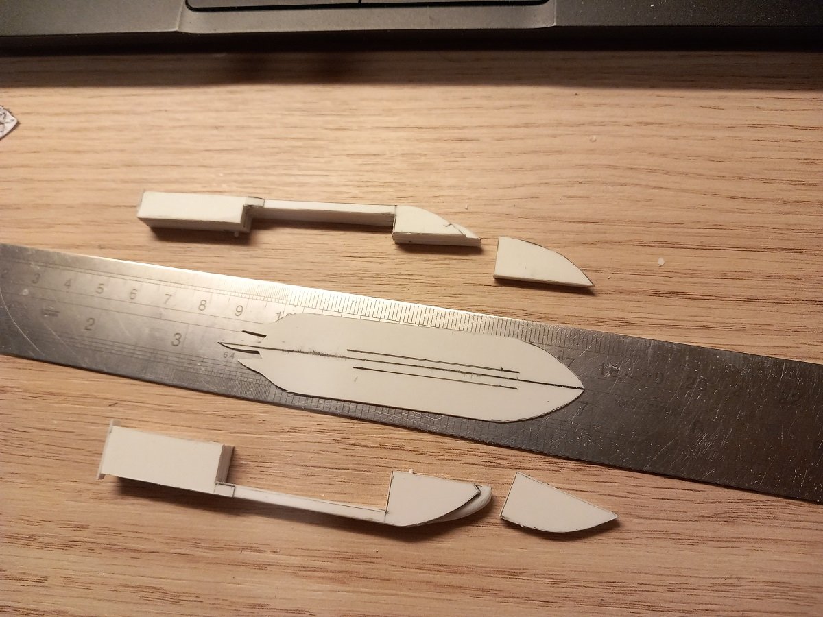
Hi Keith, Here you go. She's not exactly tiny, to go into a bottle and in all honesty I've been underestimating the complexity of this little vessel quite a lot. The hull is much more complex than I expected, which makes cutting it for insertion a lot harder than I expected. That said, those are the challenges of SIB's. The plan was quite good from the beginning, so in the end I do see solutions to all issues I'm currently encountering. For me the main planning is the vessel size compared to the bottle as well as the bottle neck. Modern vessels are much lower and don't fill bottles so well. It's therefore not the height of the mast that determines the size of the vessel, but rather the size of the hull. And it's the insertion of the hull that makes these ships difficult to put in bottles. Once you have a good view on how you'll divide the hull, the rest you can work around. The mistake I made with the Spartacus project was the huge amount of things sticking out and the gantry in front that would have made working over it, on the back of the vessel nearly impossible. I'm still not entirely sure if I could have pulled it off, but I'm quite happy with what I did with it later on. As for your request. Here is a picture with a ruler and a pen. Her bulky shape is quite evident here. These ships don't really ballast the vessel much when dredging, the weight of the empty ship is generally aft due to the engines and dredge pump. This means that they can have quite a larger trim on the stern when they are empty. However, when the hopper gets filled with the heavy sediments, the ship trims quite rapidly towards the bow. To avoid this effect, they have this funny "fat lobe" bulb on the bow. Not very elegant, but efficient nonetheless. Here are several parts. The forward superstructure will be glued to that deck. The bow part of that deck is however too wide to fit through the neck, so the outer part (In which I will also insert the bulwark) will be glued into the pieces of the hull, while I will probably make a cut around the superstructure (to partly hide the seam). This upper deck will also support the dredge line, a crane etc. The bridge with mast will go on separately, probably the last thing to go in. The largest parts are done, so I guess I'm nearing the stage of the finer details now. Unfortunately I've forgotten my tweezers... Real smart for a builder of these small scale models! I think I'll find a suitable one in the ship's hospital to continue with the detailing. I still need to refine the holes in that upper deck first. Then I'll add a coaming around the hopper.
- 70 replies
-
- 7
-
-
-
- Scheldt River
- Dredger
- (and 2 more)
-
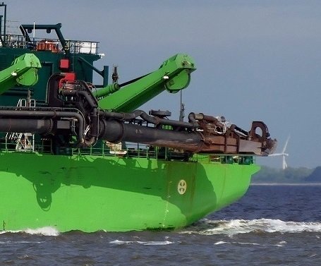
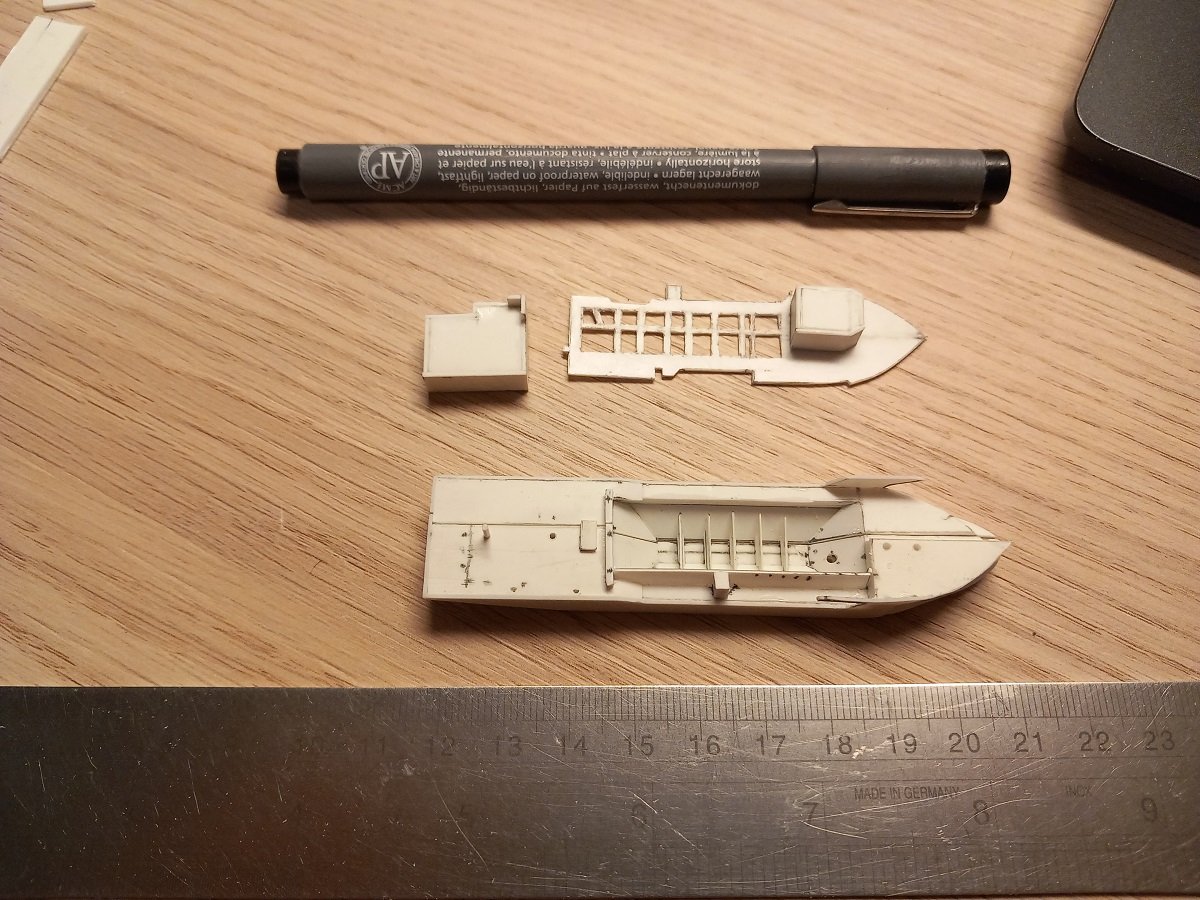
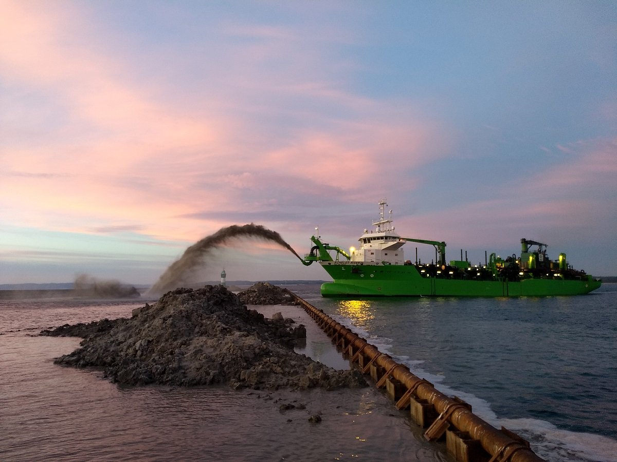
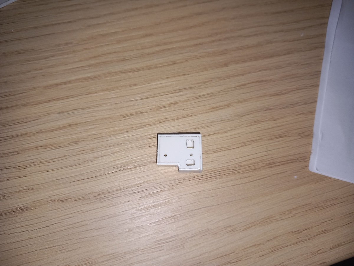
Figured I hadn't posted any pics of the real ship yet. Here is one where she is rainbowing, some vessels have a double connection at the bow and they can choose with valves whether to rainbow or use a floating line. With Scheldt River there is only one connection and if they need to rainbow on a project, they need a special nozzle on that connection. Here she's rainbowing over a sort of wall, but often they go close to a dump site in very shallow waters, sometimes grounding the vessel. For that reason they have a flat and wide bottom without bilge keels (so they don't get damaged). They are also rather wide, flat ships in order to keep a shallow draft and widen their operational range. In the above picture the dredge pipe is hoisted onboard, but you can see two sets of tracks along the portside hull. Those tracks lead to a hole underwater, where the pipe connects to the pump suction pipe. The forward tracks are used when the vessel is used in its deep configuration with an extra long dredge pipe, the aft tracks are the ones that are normally used for shallower dredging. And here you see the dredge pipe when it just came up or is just going down to dredge. As you may have noticed in previous posts, I cut the hull off center. This is to allow for the extra width of the dredgepipe alongside the portside part of that hull for passing through the bottle neck. The pipe will be mounted in its dredge position, but hinged up to pass the bottle neck. And here's the idea for mounting her inside the bottle. I'll build a tool that fits in the neck without blocking too much of it, so I can pass the epoxy hose. I guess it'll be made of steel or something else that is stiff an strong. I'll then suspend the hull from that while I pour the epoxy. The idea is to make small inverted U-brackets in each half of the hull, forward and aft, so 4 in total. When I insert the hull pieces I'll loop a small rope through each of them, sewing thread I assume. I'll attach those ropes outside of the bottle with some tape (like the real SIB builders do 😁). I'll then attach those to the tool when I insert the tool and adjust the position of the vessel (trim, list, depth). Once the epoxy is set, I let go one of the rope and pull it out by the other end. Once clear, I'll remove the tool and add the superstructures over those U-brackets to hide them. This is the aft superstructure, already prepared with positioning holes (two round centerline ones) and two larger holes to go over the brackets. And the aft superstructure in place. Also note I've started the sloped sides of the hopper. The transverse piece inside is the separation where the bottom doors are. There are 5 such separations inside, so I'm busy building those now. I'm quite limited in equipment at the moment, so I'll try to do as much as I can until I get stuck on either paint or lack of equipment.
- 70 replies
-
- 9
-
-
- Scheldt River
- Dredger
- (and 2 more)
-
Cap San Diego by mikegr - 1/160
Javelin replied to mikegr's topic in - Build logs for subjects built 1901 - Present Day
That is indeed how it's done Keith. Either connected to a pad-eye on deck or part of the hatch structure, you'd have a sling (often steel wire) connecting the hook to deck and then tensioned to avoid the hook swinging around. Fixing the boom itself was sometimes done the way it is done on the model, so it doesn't look off to me. -
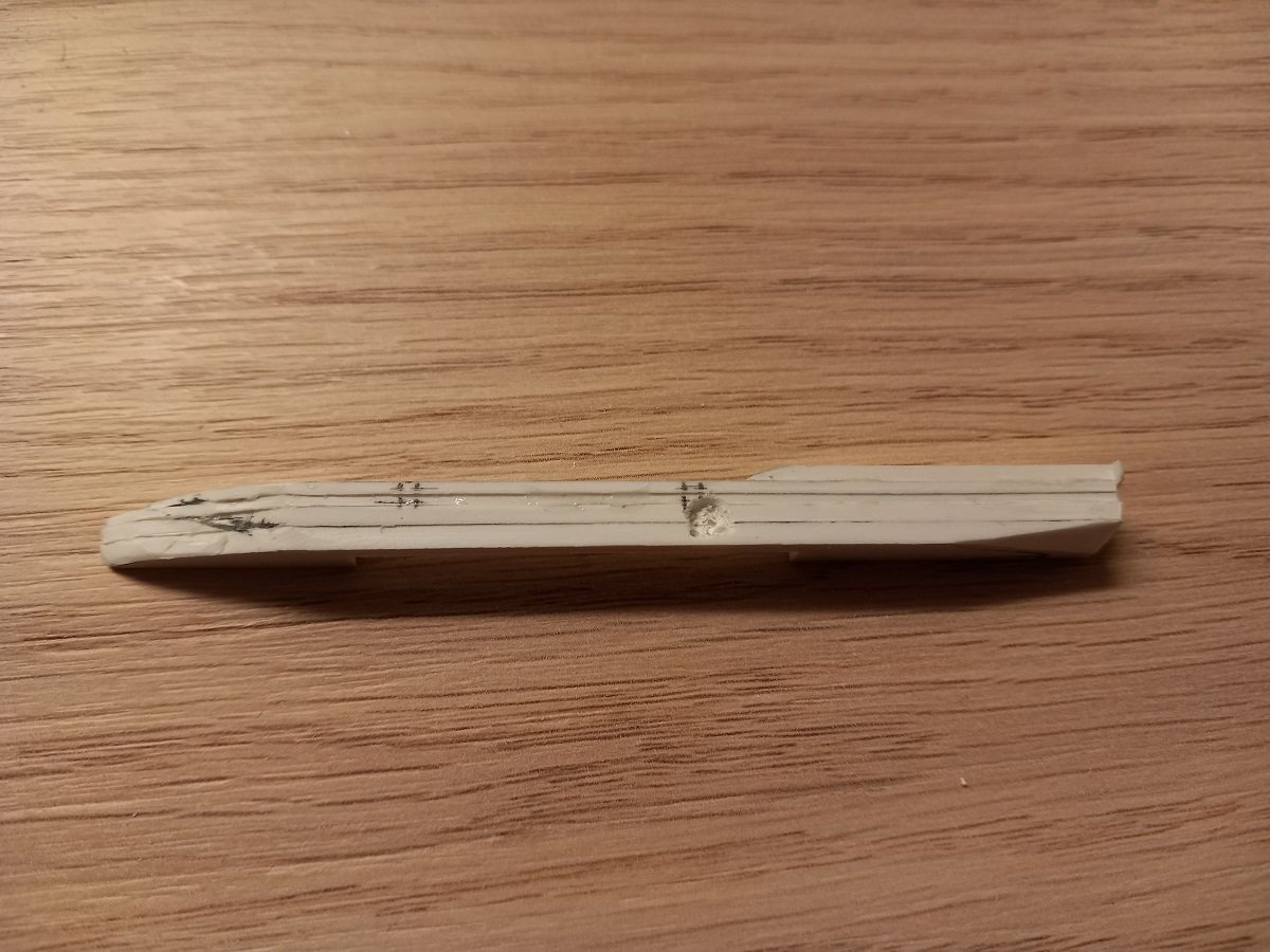
Hi @Glen McGuire, glad to see you're following. Here is an explanation on this type of ship and the depiction doesn't differ too much from what I'm going to try (except of course that these ships don't have a pipe connected to their bow while they are dredging). The link is also by the IHC shipyard in the Netherlands where also Scheldt and Meuse River were built. Trailing Suction Hopper dredger So basically I'll have the dredge pipe deployed. Obviously due to the limited "depth" of water that I can achieve, the angle won't be very impressive. I'll again put sand on the bottom of the bottom, just to the right depth to achieve a width that matches the width of the dredger with pipe deployed. Due to the bubble issues with my previous attempts, I'll be mixing the sand with epoxy rather than acrylic gel this time. I checked a few you-tube videos and it seems this is also done by epoxy artists, so it shouldn't give any adverse effects this time. So as before I'm drawing up a sequence and adapt when required: - Arrange the sand on the bottom with epoxy. - insert starboard part of the hull - insert portside part of the hull, which has the dredge pipe attached (more on that later) - put the two parts together to form the basic hull - insert special tool (to be made) that forms a long beam and is fixed on the top of the bottle neck to hang the hull (with earlier attached ropes) - pour epoxy, let dry - when hull is fixed, use acrylic gel to create tiny waves on the sea surface - insert aft superstructure - mount aft crane (still need to check in which sort of position) - mount main deck level, including opening cylinders for bottom doors and lower part of forward superstructure and pipeline - mount middle crane - mount bridge with mast At first I wanted to create some extra depth by filling the bottle till the middle of the neck with epoxy, I then realised I would only have half of the neck opening for mounting the other parts etc., which would probably not even allow to insert a tweezer inside the bottle... Dumb idea really, but it would have been cool (unfortunately still no magic skills here). I don't have the bottle with me, this complicates things a bit, but I did take measurements of the opening, drew the circle out and I can check with some certainty whether parts will fit through or not. I also saw clouds being made with medical cotton and epoxy, so that's something I'll try to create to mount around the draghead. I'll then insert it, attached to the draghead. I'm also thinking of making some objects on the bottom to make it a bit more interesting (and realistic, as dredgers catch a lot of stuff on the bottom). In the meanwhile the starboard side received its outer plate and I've started shaping the bulbous bow and stern area. I don't have any filler with me, so it'll have to stay like it is until I get back home for final finishing touches. I will, just like on Sea Installer, apply vaseline on one side of the hull and apply filler on the other, squeeze the parts together afterwards to make sure the center seam is becomes very thin. I've also carved out an opening in the portside where the dredge pipe will go. I'll explain that idea a bit later on. The pipe itself will be attached, inserted with the outer shell plate. I'm now working on the inside of the hopper. It has sloped sides and sloped internal divisions to make sure the sand is guided to the bottom doors and doesn't stay behind in piles inside the hopper while dumping/discharging.
- 70 replies
-
- 8
-
-
-
- Scheldt River
- Dredger
- (and 2 more)
-
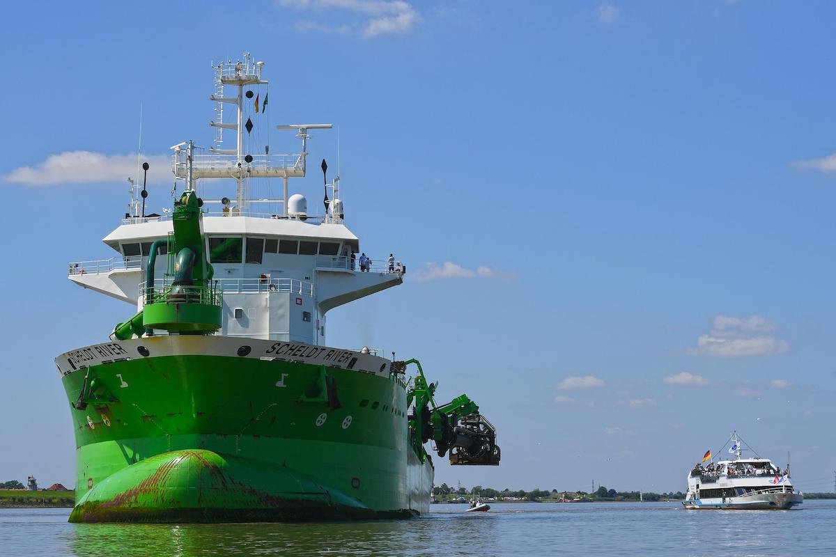
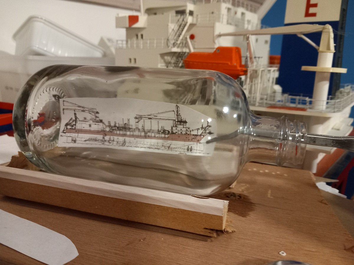
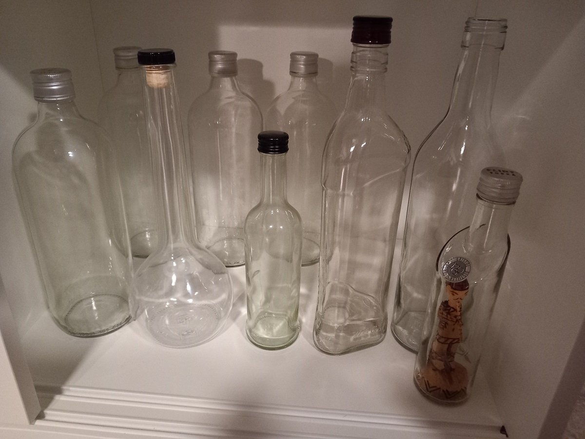
Well there it is, cat's out of the bag now. After a lot of thought and a tremendous amount of ideas, bottles and tests, I finally decided upon Scheldt River for my next SIB project. Unlike @Glen McGuire, I simply collect bottles instead of going to a liquor store to pick them out. I had a lot of trouble finding a decent bottle for my first SIB (Sea Installer) and actually poured the liquor in a different bottle in order to use the bottle I wanted. So ever since, I'm just collecting decent looking bottles. And yes, the one with the really long neck looks appealing... The wooden guy lost an arm, so either I fix it, or I try to get him out and use the bottle, since it has an interesting shape! In any case, I wanted to use one of the very large ones, trying several ships in it, but it simply didn't look right. Seems those bottles are too large (which leads me to think that I will put multiple ships in those bottles? I'm also quite specific about scales, so I actually wanted to put a 1/700 modern ship in it. That would have filled the bottle properly in length and height, but the it would have been a real issue with that neck, cutting the hull in 3, 4 or more pieces just to get it in, simply seemed to much to me. 1/2000, same scale as Sea Installer and Spartacus would have made any ship too small to fill the bottle, so eventually I decided on something in between. 1/1250 is a rather common scale and would reduce a ship's beam to an acceptable level to fit inside a bottle neck. Then of course the length wouldn't fill the bottle at all, so I decided on a slightly smaller bottle, é voilà, there we are: The drawing is just a drawing of course. Scheldt River is what they call a Trailing Suction Hopper Dredger (TSHD), which is a dredging vessel that drags a draghead on a long pipe over the bottom of a river or port. This dradhead is equipped with teeth and spray nozzles to stir up sediments, which are then sucked up through the draghead and pipe to the vessels hold/hopper. There the sediments are slowing down and sink to the bottom of the vessel while any excess water goes back to the sea/river. When the hopper is full of sediment, the hopper raises the draghead onboard and moves to an area to discharge. This can be done by opening bottom doors or pumping it to a floating line (bow connection) or rainbowing (spraying it up in the air towards a beach, also through the bow connection). In short, they are either used to keep rivers/ports at depth or to build islands/ports by bringing sand/sediment to the required places. Scheldt River has 1 sister called Meuse River. Scheldt River is a special dredger as she was one of the first TSHD's that were able to run on LNG (cleaner fuel than the regular heavy fuel or diesel). Although my earlier idea was show her dumping sand from the bottom doors I have decided to try to depict her while dredging. Further info about the idea (probably with a sketch) will follow in a later post. I've started construction of the vessel itself. Still in early stage:
- 70 replies
-
- 8
-
-
- Scheldt River
- Dredger
- (and 2 more)
-
Great job on those winches. What material did you use to make them?
-
Very sharp work, with a very high quality and consistency! Amazing work.
-
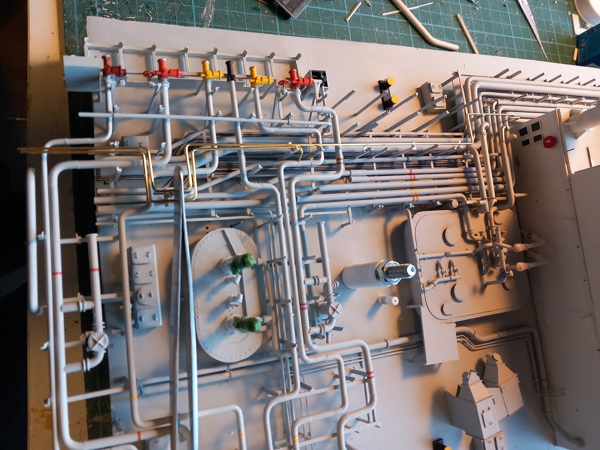
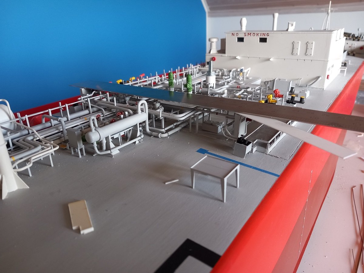
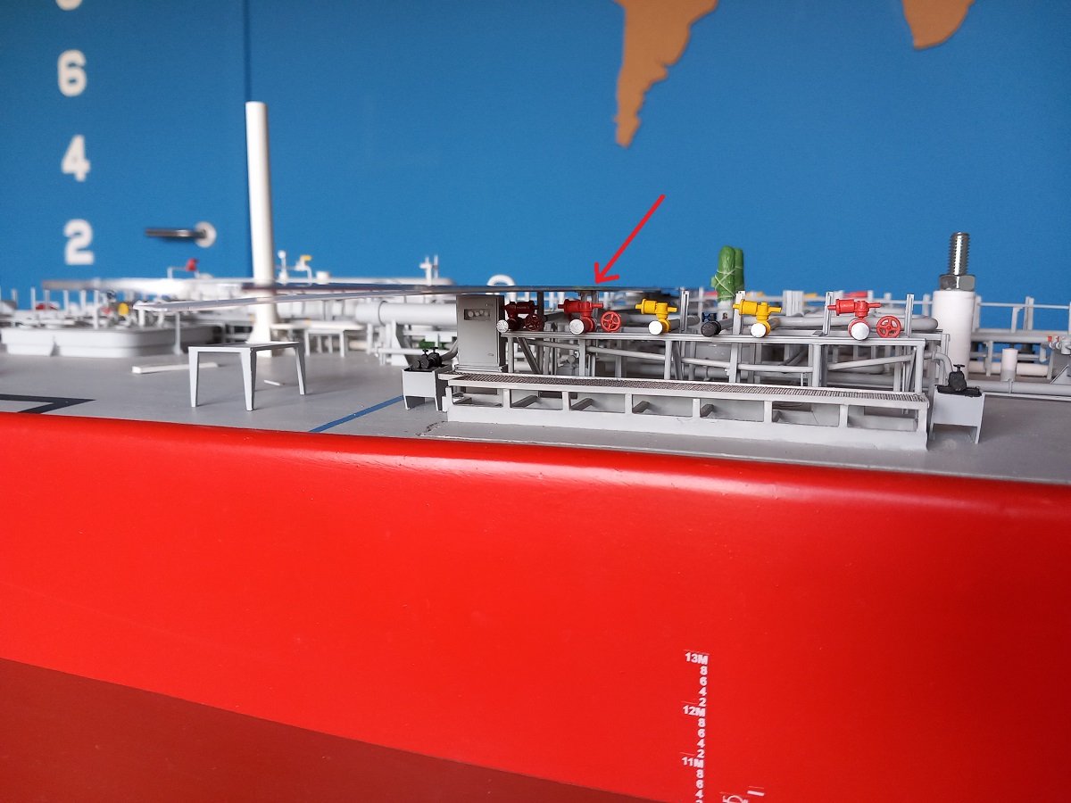
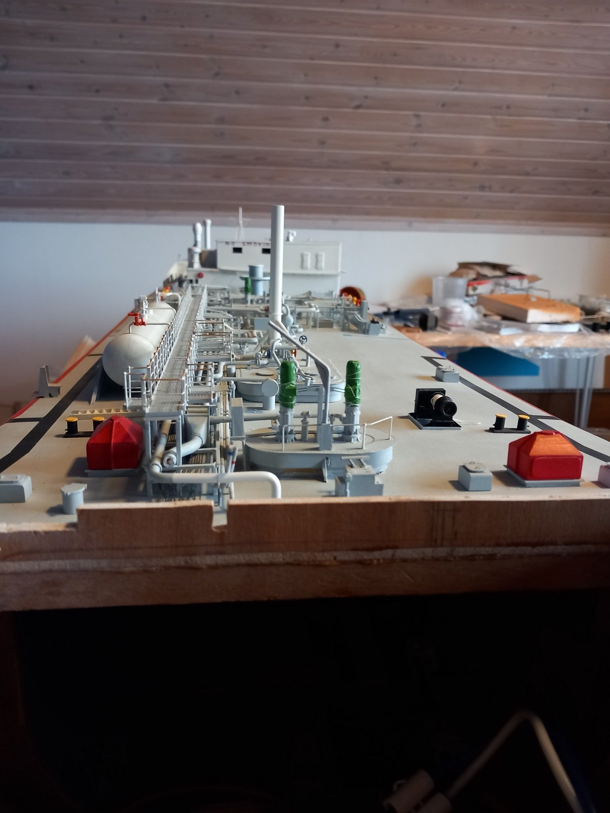
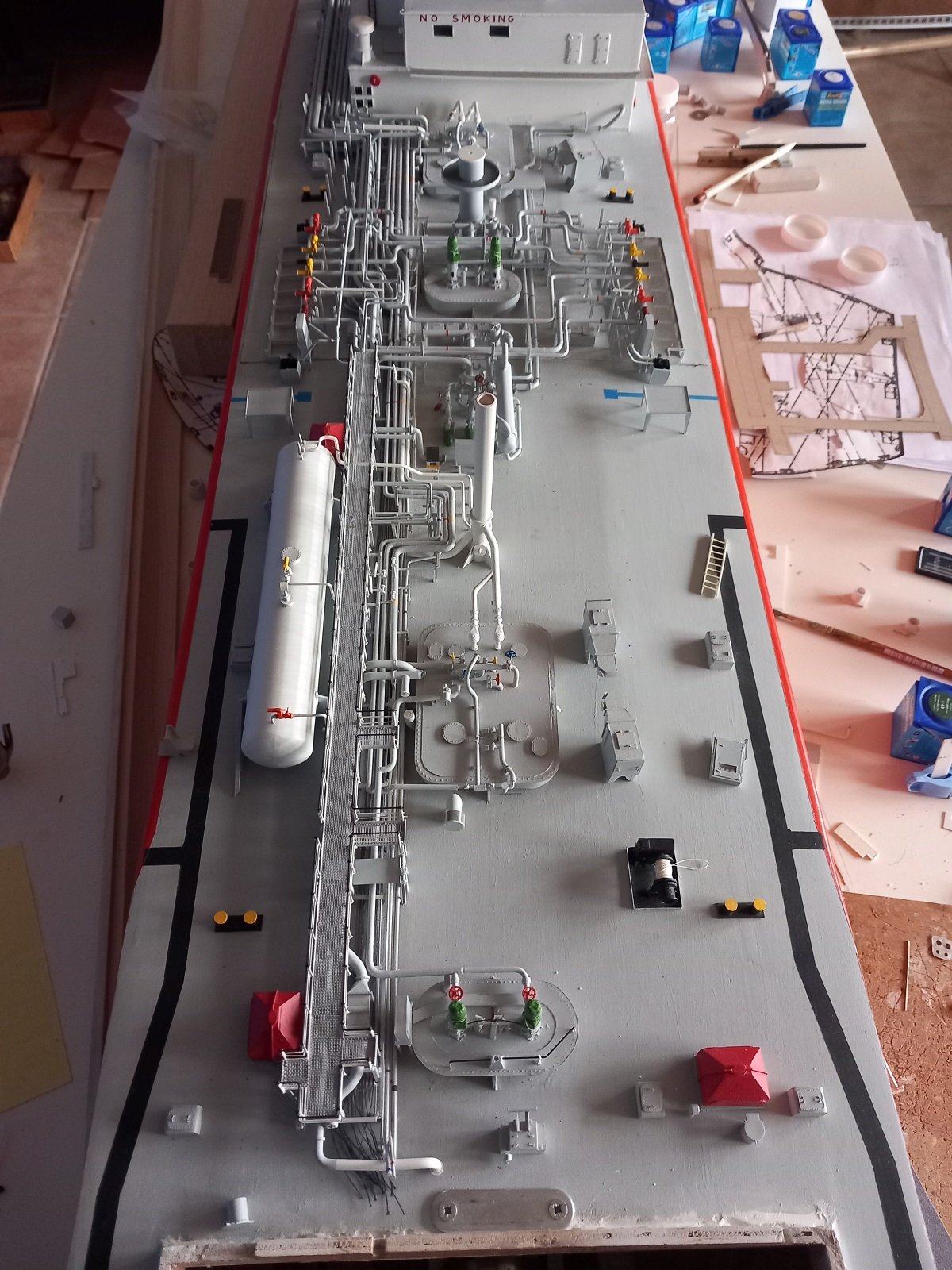
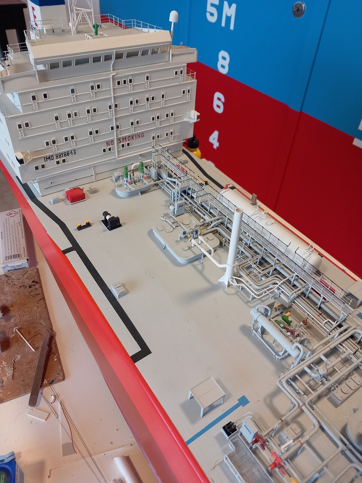
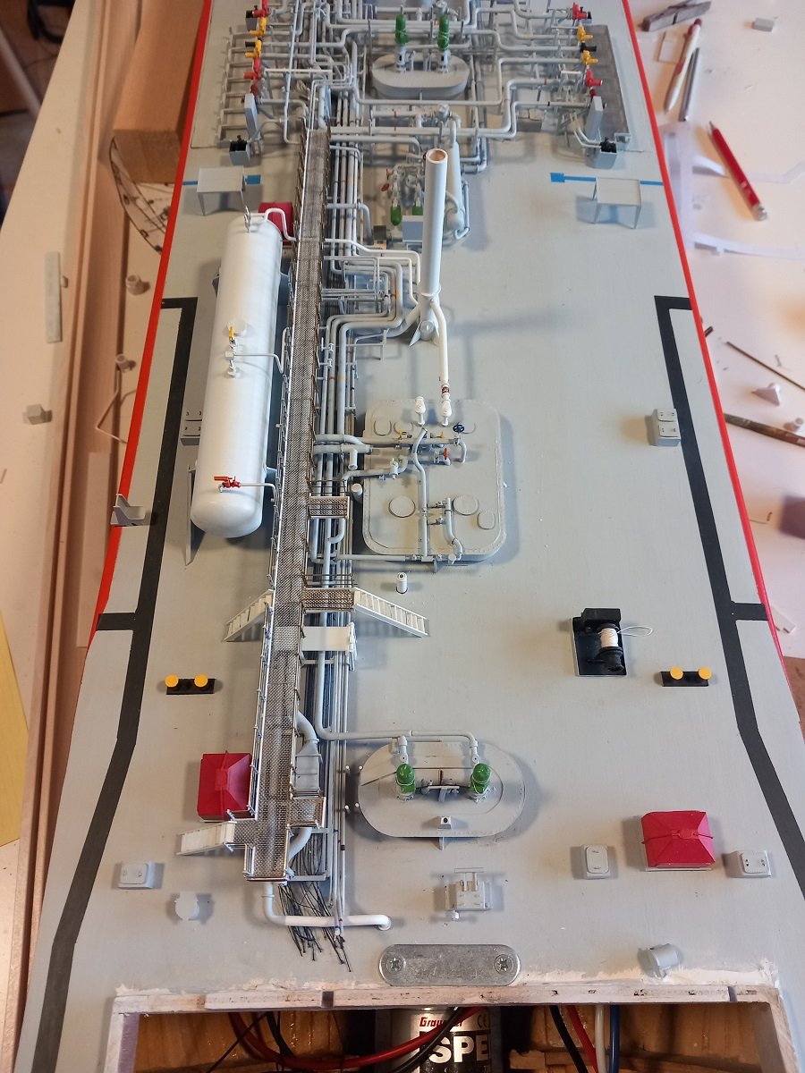
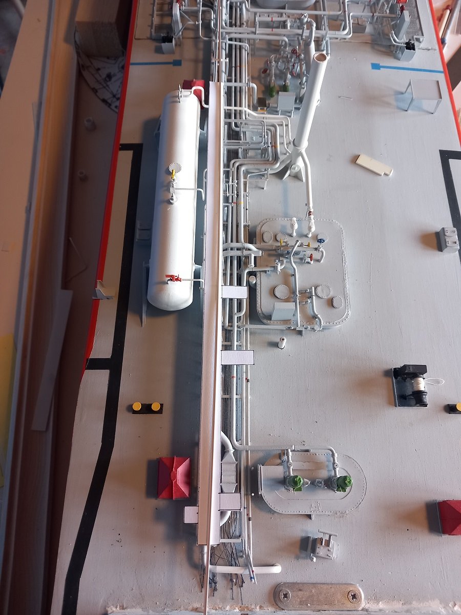
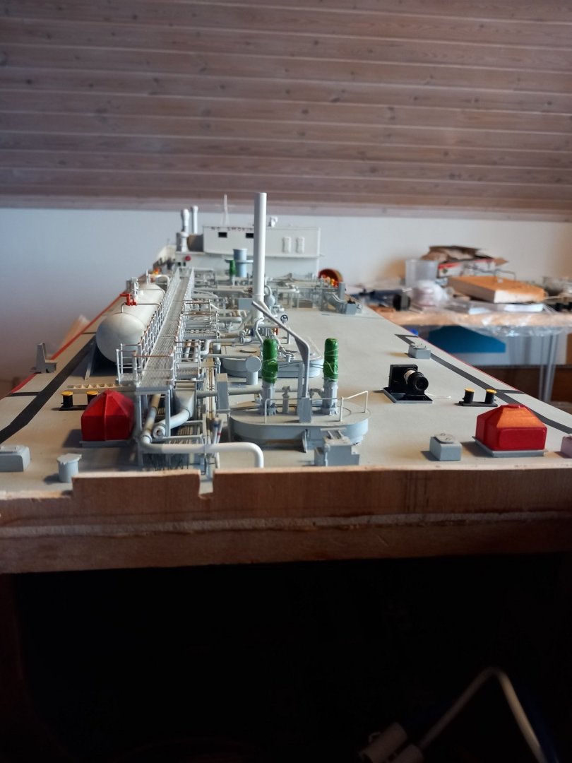
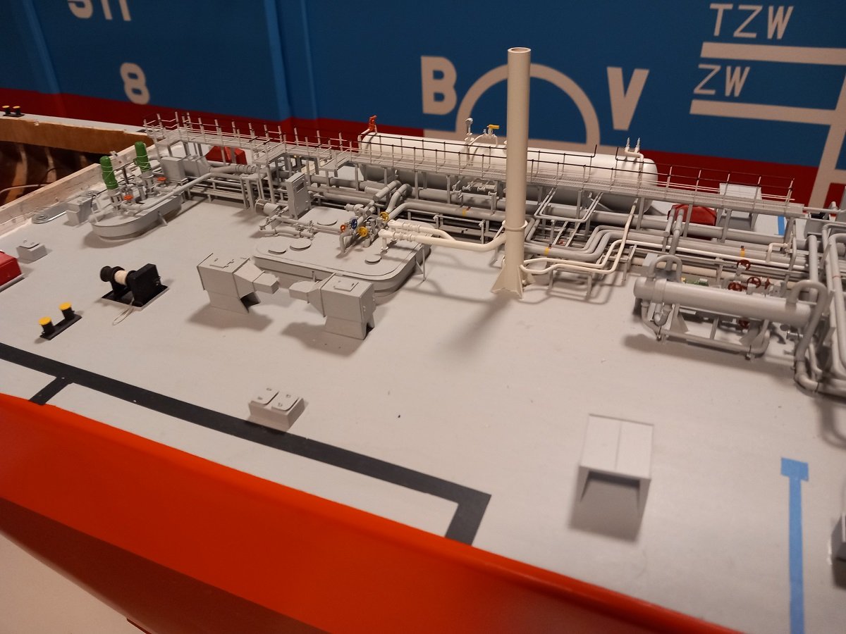
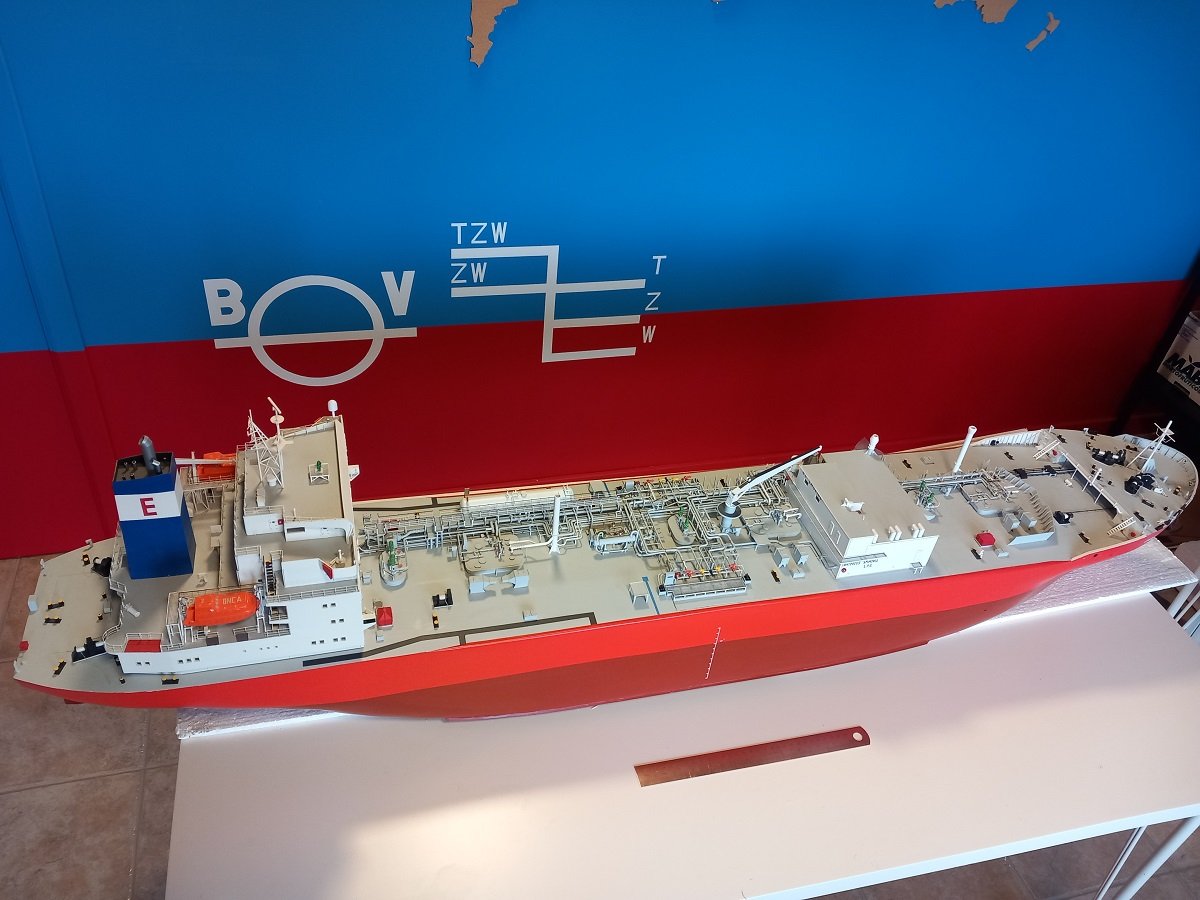
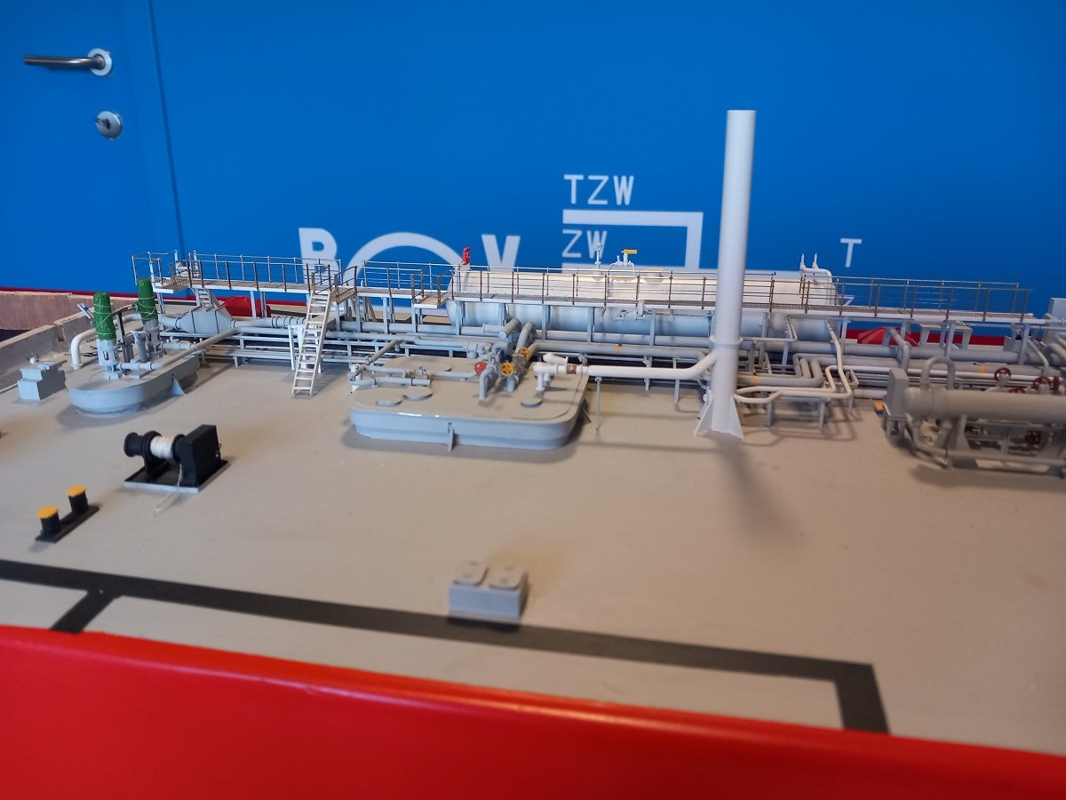
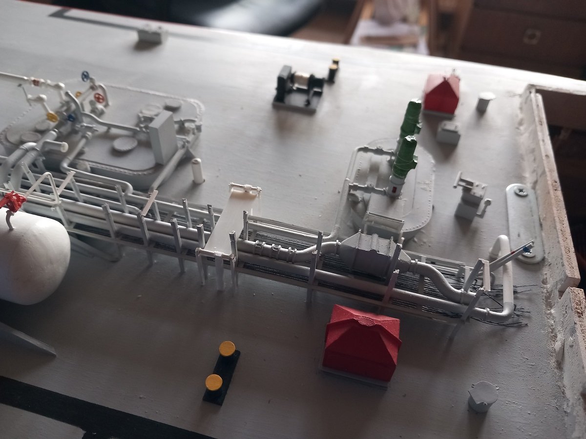
Thanks guys, so time to finish that piece of catwalk, and finally most of the back part of this ship. Note the finished pump dome of Tank 3, the davit was only dry fitted and later on removed again since I was hitting it a lot of times... That little railing on the back was something I hadn't quite thought about in the past. I wasn't planning on placing those, but since I was at it, might as well place it right? Valve wheels are also in place now, the only thing left there is a small platform next to the dome with a small stair going to the deck. Also both cargo tank safety valve (white lines from tank dome 3 to vent mast) are now mounted and painted. And a larger overview of the whole mess. And with a 30cm (1 ft) ruler in front of it. Decided to spend my some remaining time on cleaning up the workshop, including some new furniture etc. instead of continuing on the vessel itself. Still undecided if I'll keep all the stairs for the end of the construction or if start making them as I go forward. Mass production is boring, but on the other side a lot more efficient... Looking at what I did the past weeks and what lays ahead I believe that I should be able to finish her in perhaps 1 year?! Depending on other projects and family/home situation of course.


-
HMS Surprise by Vincwat - scale 1/69 - Lego
Javelin replied to Vincwat's topic in - Build logs for subjects built 1751 - 1800
Not sure, from the first angle, I'd probably prefer the right one, however in the second shot, the right one is much less bulky than the other two. I know the wheels are equally spaced, but the narrower carriage looks better. So in the end, I don't know....Definitely not the middle one. -
USS Constitution by mtbediz - 1:76
Javelin replied to mtbediz's topic in - Build logs for subjects built 1751 - 1800
Very impressive! Both the ship, and primarily, your skills! -
Marvelous ! 👍
-
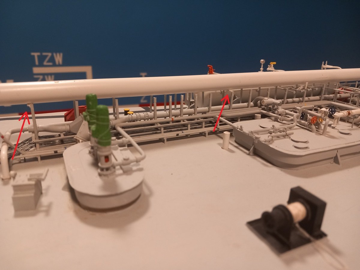
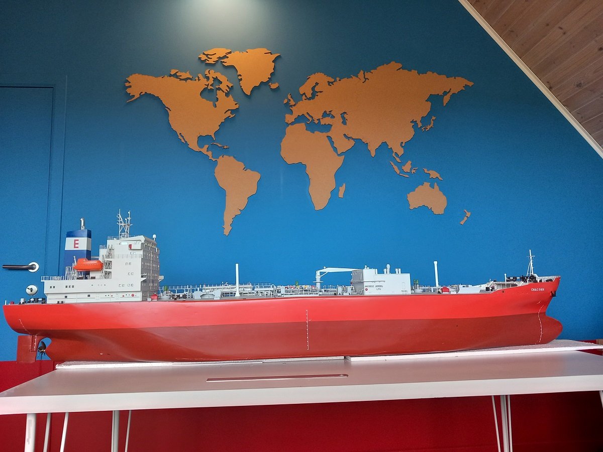
Thanks Keith. It's actually a piece of the vessel where I got my captain's promotion. The funny part about it is that it was a Belgian flag vessel and somehow the Plimsol marking is in Dutch. The abbreviations ZW are for Zoet Water etc. Which I hadn't seen on any vessel, including a lot of other Belgian flag vessels before. Normally those markings are in English... Since it has a blue freeboard I used that blue as a background for a large cork world map, where I marked a lot of voyages I did. Still working out a way to actually connect the dots though. Putting pins in the cork is not an issue, but I'm not too keen on putting pins in the wall for the "sea waypoints". So for the time being there are just pins in port locations. I used different colours for different vessels/voyages.
-
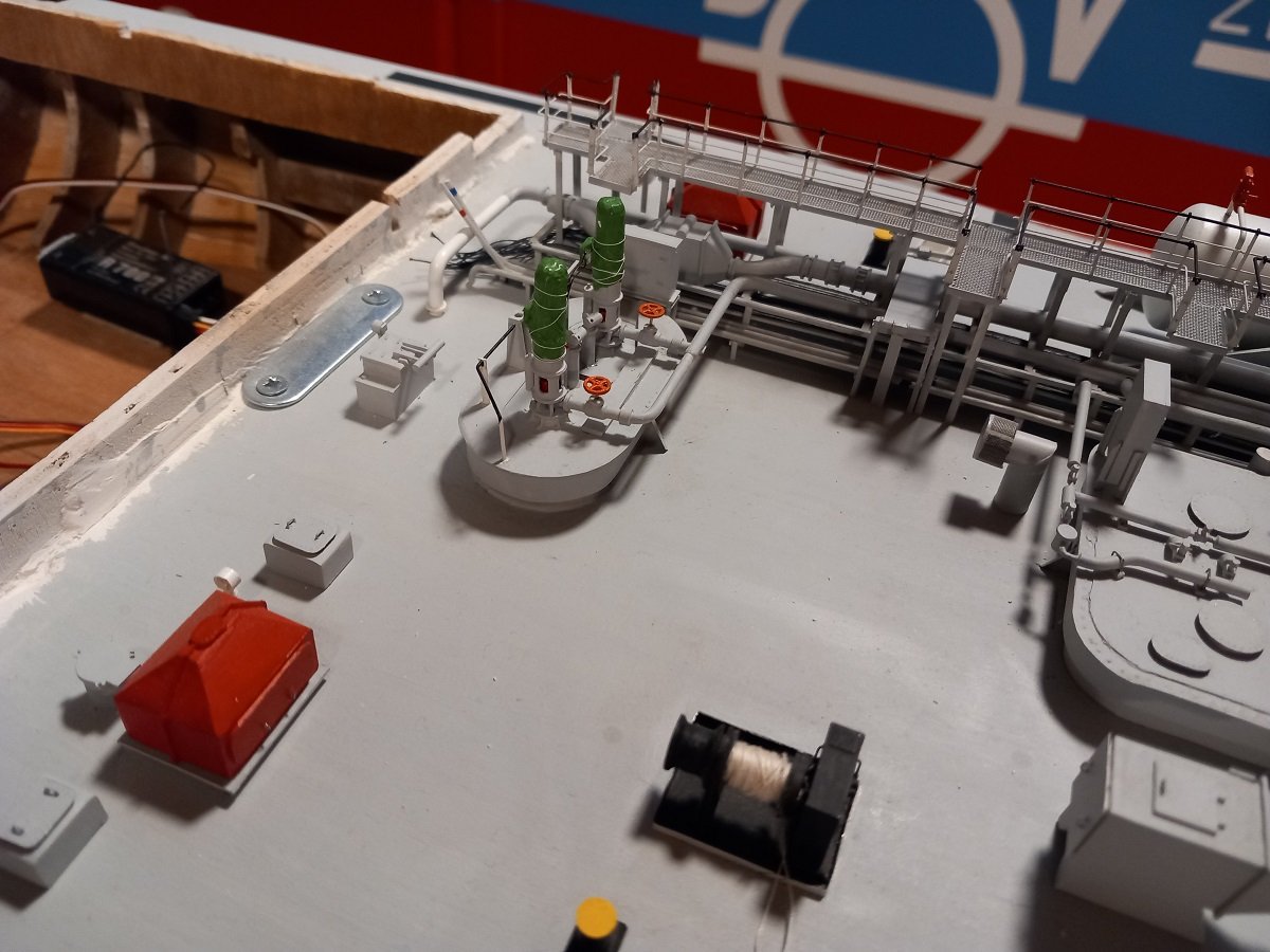
Hi Tim, Problem is, I live in Belgium. It's not really allowed to use RC ships (or swimming) in any public water. What little water that is available or remote enough not to be noticed, is difficult to access. The pond that I used in the past is actually a buffer for the fire brigade in an industrial zone. It's sides are built up by rock in mesh cages, placed in a stair/step way. Driving a cart inside with the ship on it is therefore not possible. Most of our ditches are also way too steep to drive a wheelbarrow-style cart towards the water. I will however keep looking for an easier way. Since my break is nearing its end and I have to get back to sea, I had to set a target, I guess that will be the installation of the catwalk on the aft part. I believe it's achievable since most of the details on the aft are now complete. Here you see the rollers and plate system for the mooring lines dry fitted over the piping. Although some details are not strictly necessary to be placed before the catwalk goes on, I did decide to really go aft to forward and complete whatever I can. Starting with gluing the parts you see on the right edge of the above picture. I then moved to the pump dome of tank 3 and so on. I had a slightly oopsie with the catwalk. Adjusting the length of the brass top wire, I dropped the pliers on it. Seems the supports couldn't handle the force. Luckily they are brass and I was able to bend them more or less straight again. And here it's partially painted and dry fitted in position. The stairs are just there to show how it should be arranged. They are not the stairs for those positions.


-
Well worthy of being placed in a museum somewhere. Great quality of construction along with a rare subject with educational value.
-
I don't think that's poor planning at all. It's basically the point of SIB's. If it's not hard or just straightforward, then what's the point? Adjusting the bottle or the scale just makes it easier and that gives a less brilliant effect. Having all those pieces fit nicely would also require so much planning and even construction that you'd already be halfway in the build before you discover all possible issues... That way you'd never really start a build! ( and that's not your style is it? 😋)
- 185 replies
-
- 6
-
-
- Flying Dutchman
- Black pearl
- (and 2 more)
-
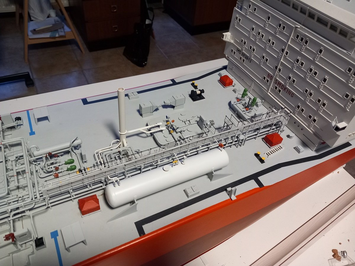
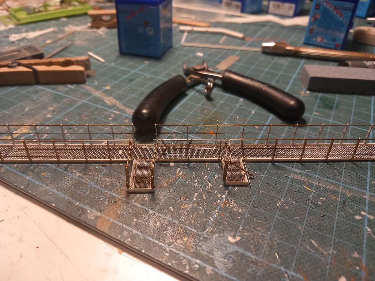
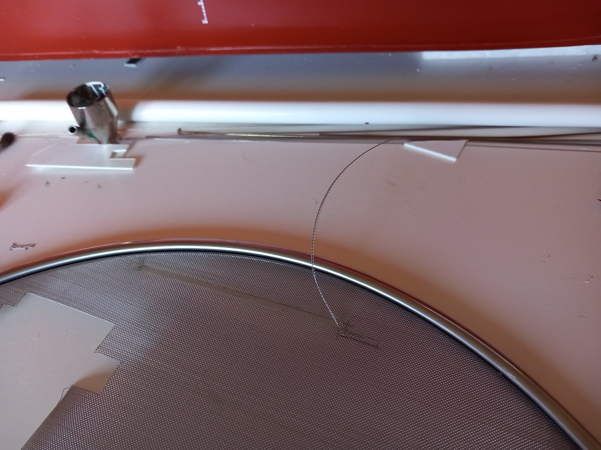
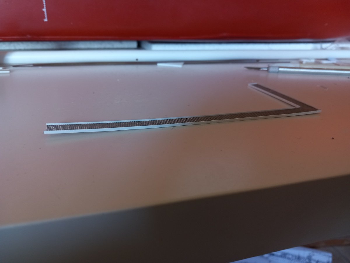
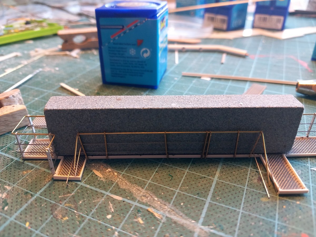
So the tedious job of catwalks has started. In one way I looked forward to it, since it's the beginning of the end, but on the other side I wasn't too keen on starting it, since it's a tedious job of cutting out all the stanchions from the PE sprue and measuring and fitting etc. First things first, a paper template to get some correct fitting. It has a few platforms on the side where stairs are mounted. Some of those are on the GA plan, but some are omitted, so the paper template really is necessary to get the position of all of them correct. On top is a styrene L-shape. As you can see, they aren't quite straight over such long lengths. The idea is that the steel grating inside will give the strength and rigidity to the catwalk. However I have already some experience with these gratings and cutting them. They have a tendency to bend quite strongly. This is a very narrow strip that I tried for a small scale project. And this is the now 10-year old catwalk from around the deck house. Much less pronounced, but as you can see it does bend the styrene L-framing as well. I can probably fix this one by supporting and clamping though. The solution for this very long catwalk was to cut tiles. I basically cut 3cm long tiles (in reality the grating is also mounted in pieces rather than one long length, so no issues there). I glued the tiles in, with some weight on top to keep it all flat while gluing. Later on, I used the same trick to mount the railing on both sides. I glue the railing stanchions to the horizontals, so it also adds some rigidity to the whole thing. In the meanwhile I figured I can finally go ahead with the final detailing on this aft part. The catwalk is the top layer, so once it's mounted this part of the vessel would be finished near the center. I'm now checking all details that are still missing from aft to forward (of this section). Some of it was already made, some I still need to make. Here is a bridge with rollers on both sides to pass the aft spring line from the starboard winch over to portside of the vessel when mooring portside alongside. You can also see some manholes etc. that will be mounted just in front of that accommodation block. Time for measuring and gluing.

-
You definately built that hull sturdy 😵. What is her empty weight (without that ballast)?
-
I would also go for glue first, paint later. In case of first painting and then gluing: If the curve doesn't fully match with your hull, you'd have the risk of it coming loose since it would be glued to the paint instead of directly on the wood. You could of course paint first, with the position of the sponsons masked (and glue them on later), but that would be difficult with the risk of having to touch up on the paint later....
-
Looks brilliant. Museum quality!
-
Are you sure the 2 paints are compatible? I had something similar in the past, but the drying wasn't the issue. I used acrylic primer over a layer of top coat and that didn't seem to work... A real pitty though 😭, your masking was top notch, no signs of bleed...
-
Great looking Dutchman (At least one on this planet then 🤣)! So I was recently thinking about your project and I was thinking about the little parasols you get in some drinks. Perhaps that concept could be an idea for the whirlpool. Insert with head first, tilt it with the head down and open it by sliding the mechanism down. You'd have to design your own parasol for proper size, shape and material though. On the upside, you could make the stick long enough to touch the top of the bottle, so it doesn't float. Just another brain fart. A solid cone is still preferable, but I just don't see a good solution for the moment. I guess this project would be easier with a bottle in upright position (neck on top), but you'd need a low, wide bodied bottle for that (I have one like that, but with an extremely long neck).
- 185 replies
-
- 8
-
-
-
- Flying Dutchman
- Black pearl
- (and 2 more)
-
haven't actually remeasured it recently, but she should be 1m65 (=5ft 4). That's why handling her by the aft and center coamings has proven to be the easiest way to handle her.
-
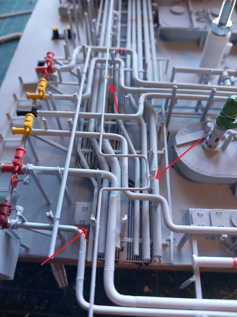
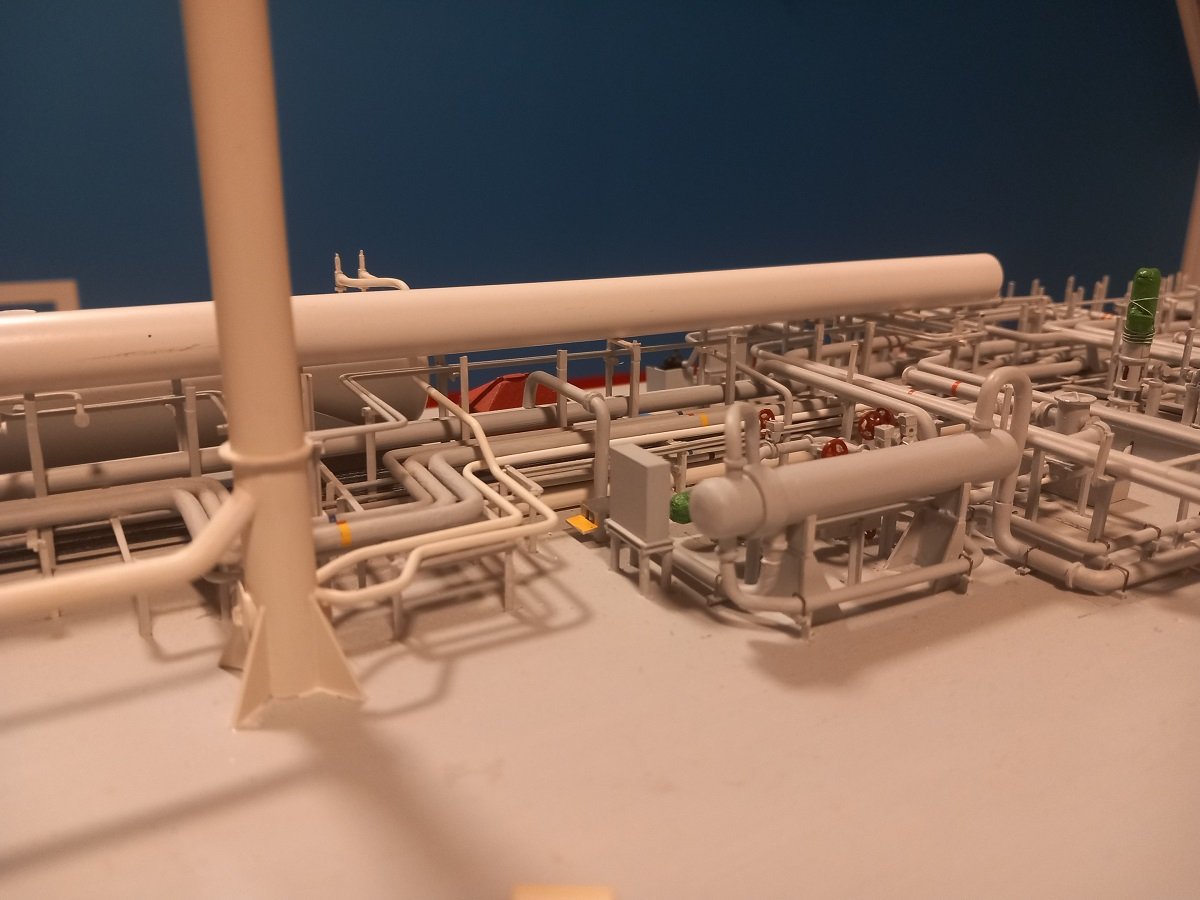
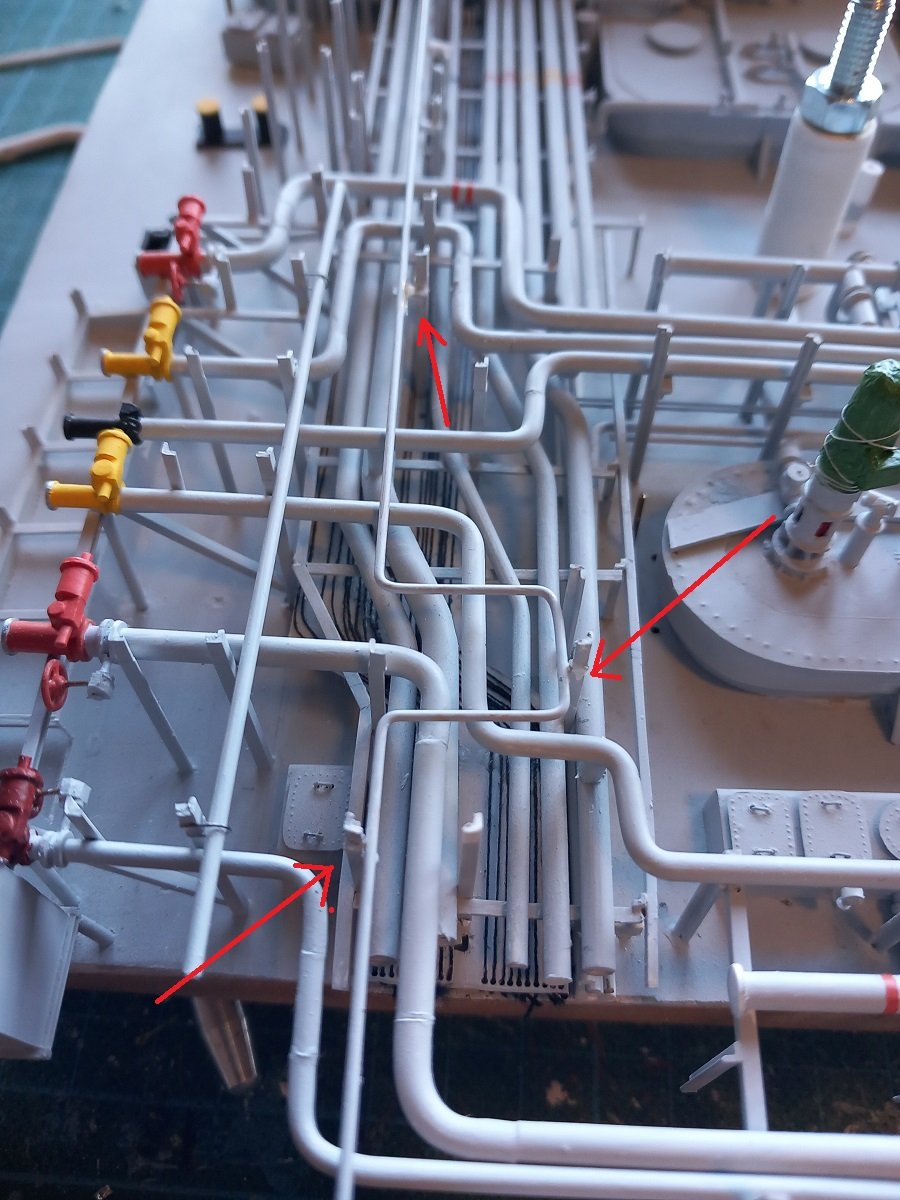
Hi @KeithAug, Full load weight would be around 30kg (66lbs), but normally I sail with around 22kg (48lbs). I have indeed also seen converted aluminum ladders with a rope/chain hoist system that would lower ships to the water etc. However with this kind of weight it would be difficult to use that option. On the other hand, considering how she turns out, I doubt I'll be sailing a lot with this one. I need something more maneuverable for the future (that's going to take a while though). So exciting times (for me at least). I've now completed the top layer of pipes. Not without hurdles though. The deck, and mainly the hatch, has warped a bit, so it's difficult to get things straight and at the correct height. After the usual dry fitting etc. I painted it all, to then figure out that the pipes looked a bit too bent to my liking. It dropped down considerably towards the forward part, with all the straight vertical supports, it was a bit too obvious. Looking at it again, I actually had to drop the backside a bit. So I decided to do some surgery, cut off 3 supports on the aft and lower the aft end of the pipes a bit. Quite a stressful surgery since I had to cut with my knife in the middle of the forest of pipes and support. First dry fit. In following 3 positions I had to cut off the supports and realign the pipe (I removed one of the 2 pipes before cutting as well). And then, after this was successfully performed and all reinstalled, it was finally time to determine the level for the catwalk. I first had to decide the highest point of the piping. I then put my steel ruler on that position, resting it on some of the supports and leveling it out transversally. As you can see, I used a 0.5mm piece of styrene on those supports to level it out. I have a certain margin since I'm using L brackets (like the real thing) to level out the catwalk. The L-shape allows me to go up and down a bit on the vertical supports. I then glued the first transverse support on the portside. Once fixed, I glued one on the starboard side (arrow, underneath the ruler) And once I had the level at the highest point, I continued aft. I used a large diameter styrene tube as a ruler, since it's big/long enough, but doesn't weight much. I did the same in this direction, mounted the tube over the supports, resting its forward end on the new transversal PS support. Then leveled it out using a spacer on the aft supports and then glued the first L-shapes along the length. Forward part of the tube on the fixed support. And the aft end, with the first L-shapes glued in position (arrows) After contemplating several ways to make those catwalks, I decided to make them off the vessel and mount them when complete. The alternative would be to put L-shapes on the supports and later on put the gratings in. However, I'm afraid this way I'd have waved catwalks, also mounting the railing will be difficult, certainly around that deck tank etc. So the idea now is to measure everything out, make a template from cardboard or paper and then build the catwalk, including railing, on a flat surface. I'll then mount it and probably add the last transversal supports when the catwalk is ready. The catwalk construction will take a while I guess.