


Javelin
-
Posts
632 -
Joined
-
Last visited
Content Type
Profiles
Forums
Gallery
Events
Everything posted by Javelin
-
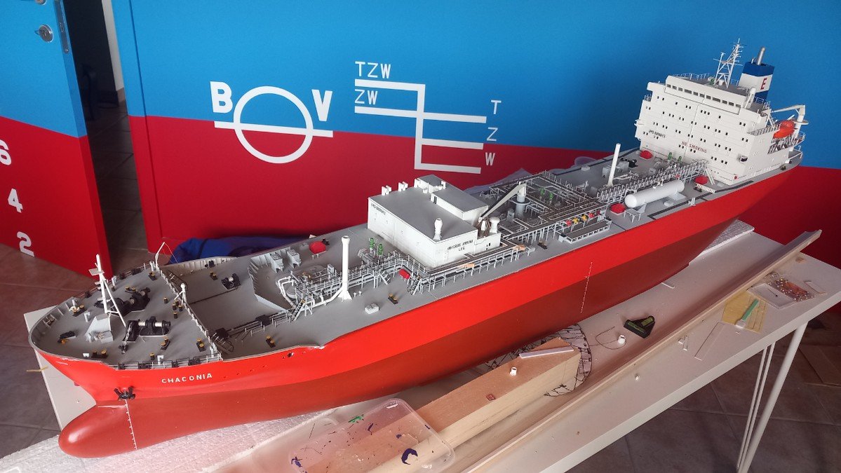
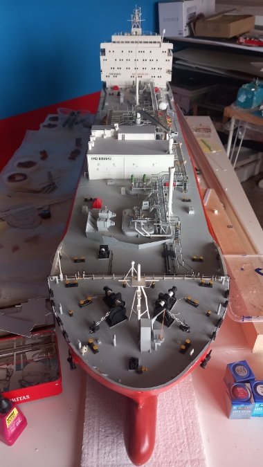
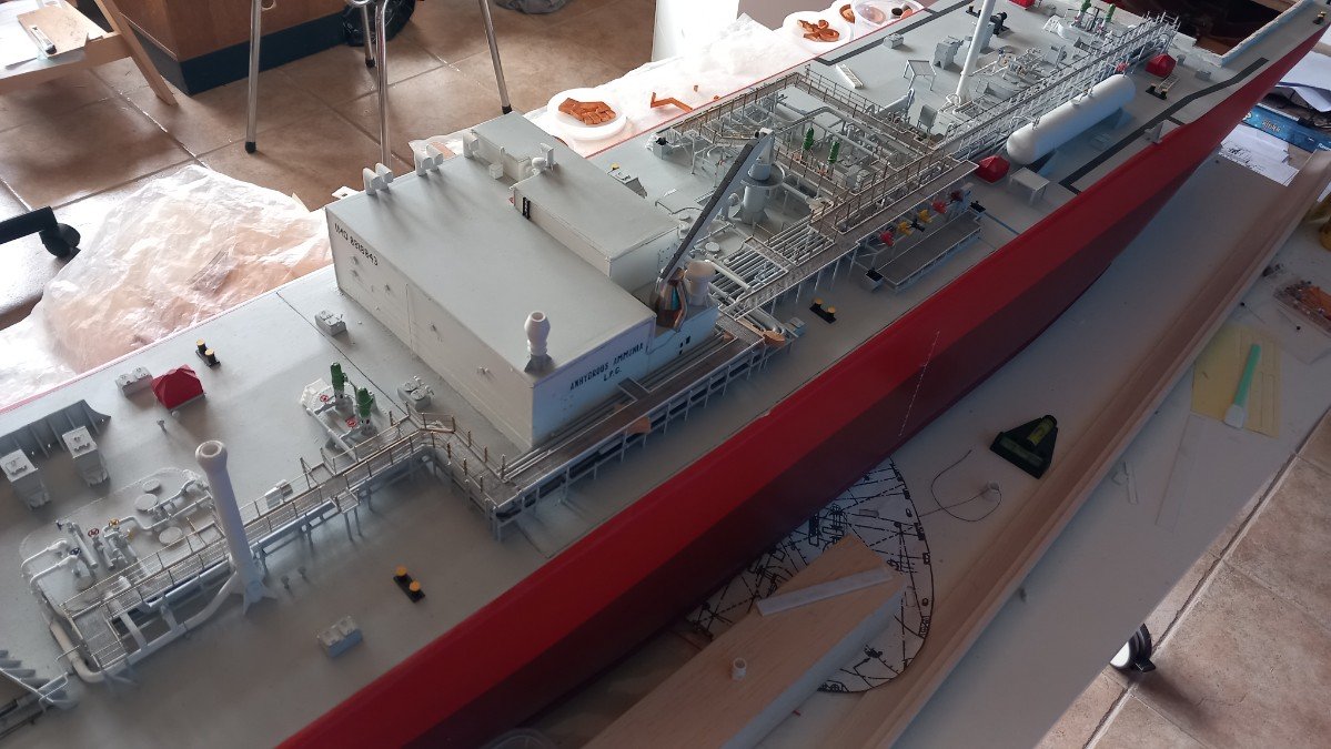
 Thanks Paul, I must admit these overviews force me to take pictures from bigger distances due to her large size. A lot of her imperfections are therefore not visible on these pictures. I'd even go as far as saying I'm probably one of worst builders in this scratchbuilding part of this forum. I never quite succeed in getting things straight, always use too much glue and painting is mediocre at best. I have improved over the years, but I can not undo what I did 14 or more years ago. On her portside bow and foremast you also see damage from a collision with a bridge. Paint missing, mast severely damaged. I decided to treat that repair as a seperate project and first finish the ship. I wanted to mention that because for once it wasn't a construction or painting error by me. 😄 (it was a manoeuvring error by me though 😆) One advice for anybody building a ship this size is use of a movable table or at least a set-up that allows you to move around the model. You can't see it in the last picture, but the table feet are from Ikea and end in swiveling wheels (with brake). This allows me to turn and shift the model anyway I want and allows me to bring certain parts of the vessel closer to better lighting or powertools when required.
 -
Incredible piece of work Keith. That dollar bill is really showing how brilliant this build is. Not only the building, but also the painting of such tiny pieces with such a sense of realism is simply outstanding!
- 457 replies
-
- 5
-

-

-
- sternwheeler
- Hard Coal Navy
- (and 1 more)
-
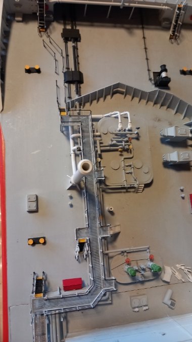
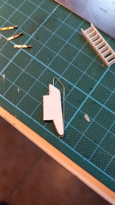
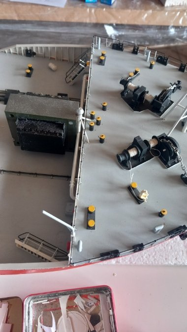
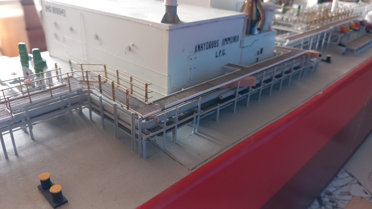
Thanks, happy to hear someone might have a use for my posts. The jig was built 10+ years ago, I guess I was clever back then. The jig for the railing is however the 2nd version. The first one ended up being cut up and used in pieces in another build. I didn't really think of continuing this build I guess. In any case, the forward PS part of the ship is also finished. The ladders aren't glued though. In this top view you can see the railing on main deck that connects the catwalk stair with the stair to the foc'sle. I did have some time remaining, so I also built the 2 small stairs and 1 long one on the SB side of the catwalk (without railing or paint for now). And an overview:
-
Late to the party as ever. I've contemplated drilling holes in bottles for past projects, but always considered it cheating, just short of heresy. That said, and for the great purpose you have in mind, I fully approve of this hole and I'm glad you tested this because I was certainly curious whether it could be done without wasting a bottle. I love this project. Perhaps you could use cotton wool (perhaps coloured) around the leds to simulate fire? Should not be too difficult to get into the bottle as well. I have a cotton wool smoke trail of a missile that hasn't lost its shape in nearly 20 years and I didn't treat the wool with anything. Not really sure how it will spread or "contain" the light though...
- 156 replies
-
- 3
-
-
- Queen Annes Revenge
- bottle
- (and 1 more)
-
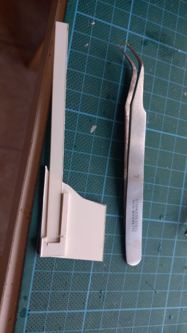
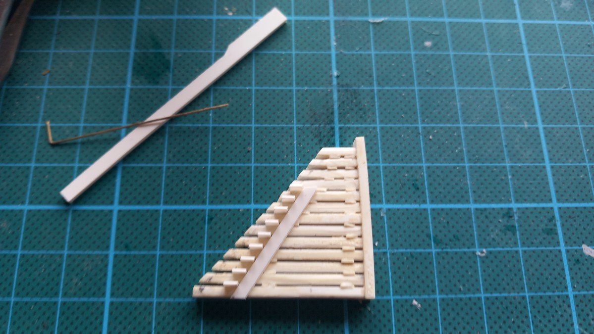
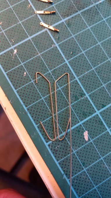
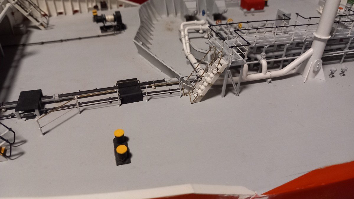
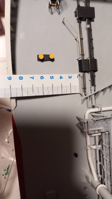
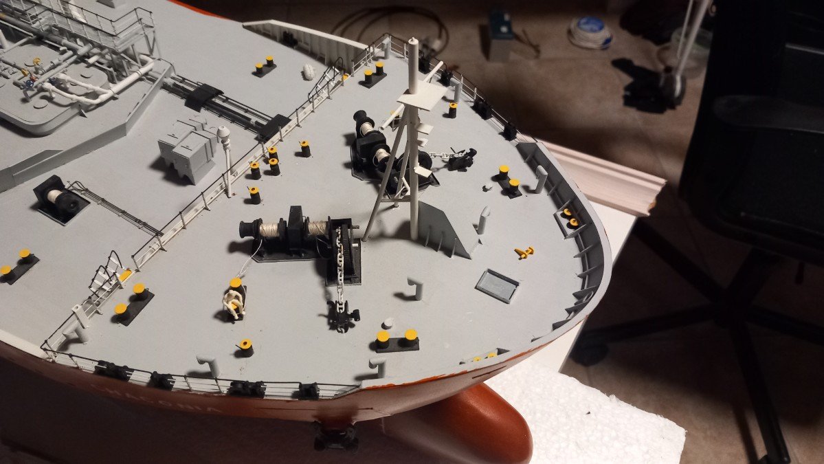
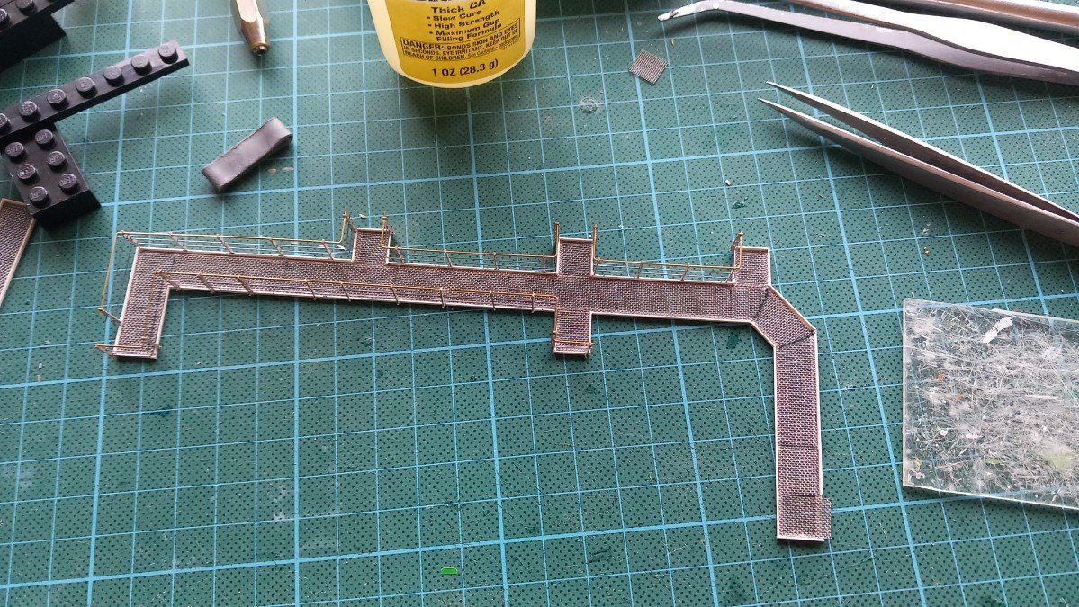
First I finished that forecastle by adding the bosun store hatch and associated davit. For the davit handling rope I used normal orange sewing thread to replicate the commonly used orange polypropyle rope. The experience of actually finishing an area was quite addictive, so I decided to move just aft of the forecastle and finish that area first. Truly finishing it, also means creating the stairs, a task I'm not looking forward to. There is really a huge amount of stairs on this vessel and all are different. I was planning to leave them for last, but I believe this may have resulted in me not making them at all or ending up with a builder's block. So now on to the forward part of the deck, where I just installed the catwalk. First stair steps. I made a new jig for the steps. I already produced a lot of steps for the future as well. Then they go in the jig. And once we have a stair, I produce the handrails, also with a jig. This jig has both sides of the rails, but the length is not fixed. So I make the sharp end (upper)first, the check the required length with the stair. Then I mark it and form the blunt (lower) end of the rail. There are 4 long and 2 short stairs on the part in front of the deck house. Here is the forward most stair. You can also see part of the railing on deck level that goes from that stair to the forecastle stair. This is another part of the "safe acces to tanker bows" as required by regulations. And here is one of my secret weapons: I use a lot of these free paper measuring tapes from Ikea and other shops. Their flexibility comes in handy, from time to time I also cut them in smaller pieces for easier use.

-
She definately looks good. And what a pace of construction, from January start till finishing now! It takes some sacrifices to a model's quality to make it RC if you're not willing to continuously repair it. However on your model there are few visible compromises! What I don't like too much about such ships is the single prop/rudder configuration that limits the amount of manoeuvering one can do and increases the minimum required pond size to comfortably sail around.
- 51 replies
-
- 2
-
-
- Puncher
- escort carrier
- (and 1 more)
-
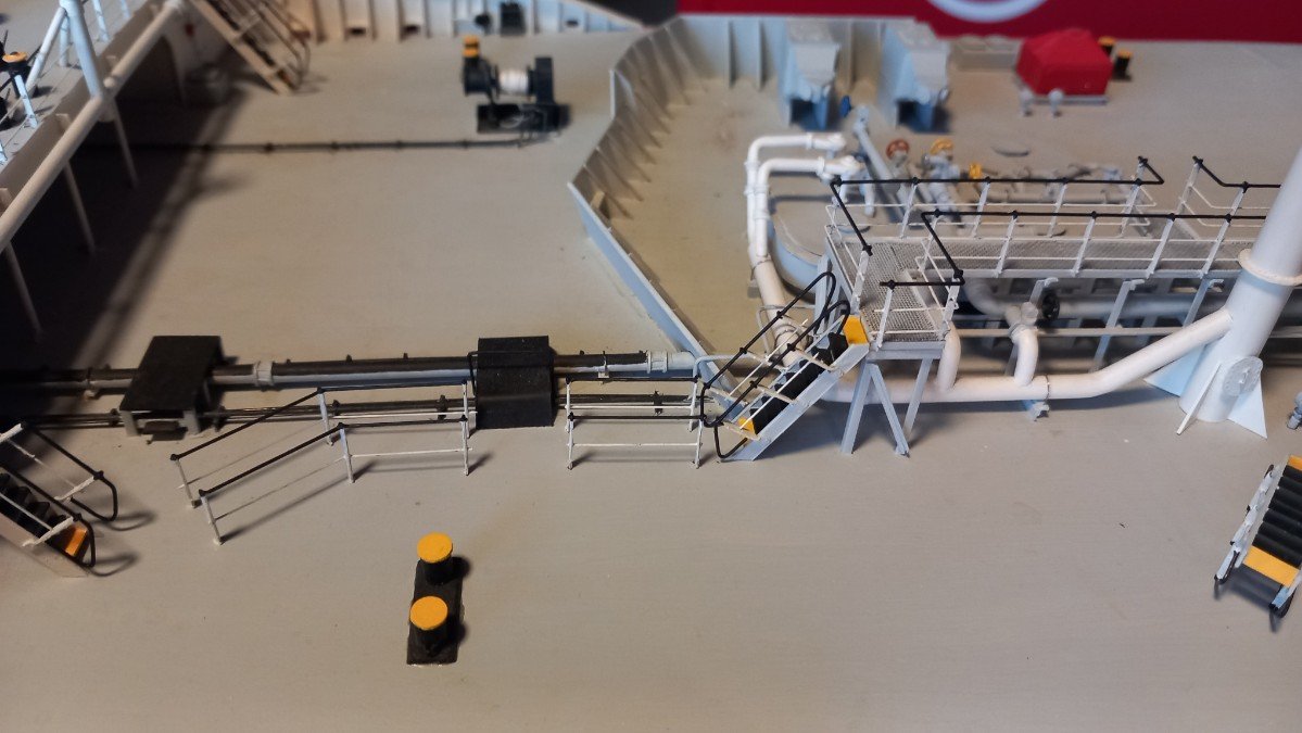
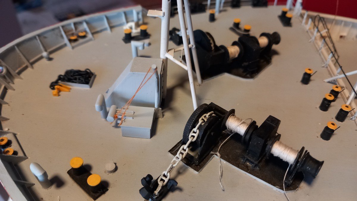
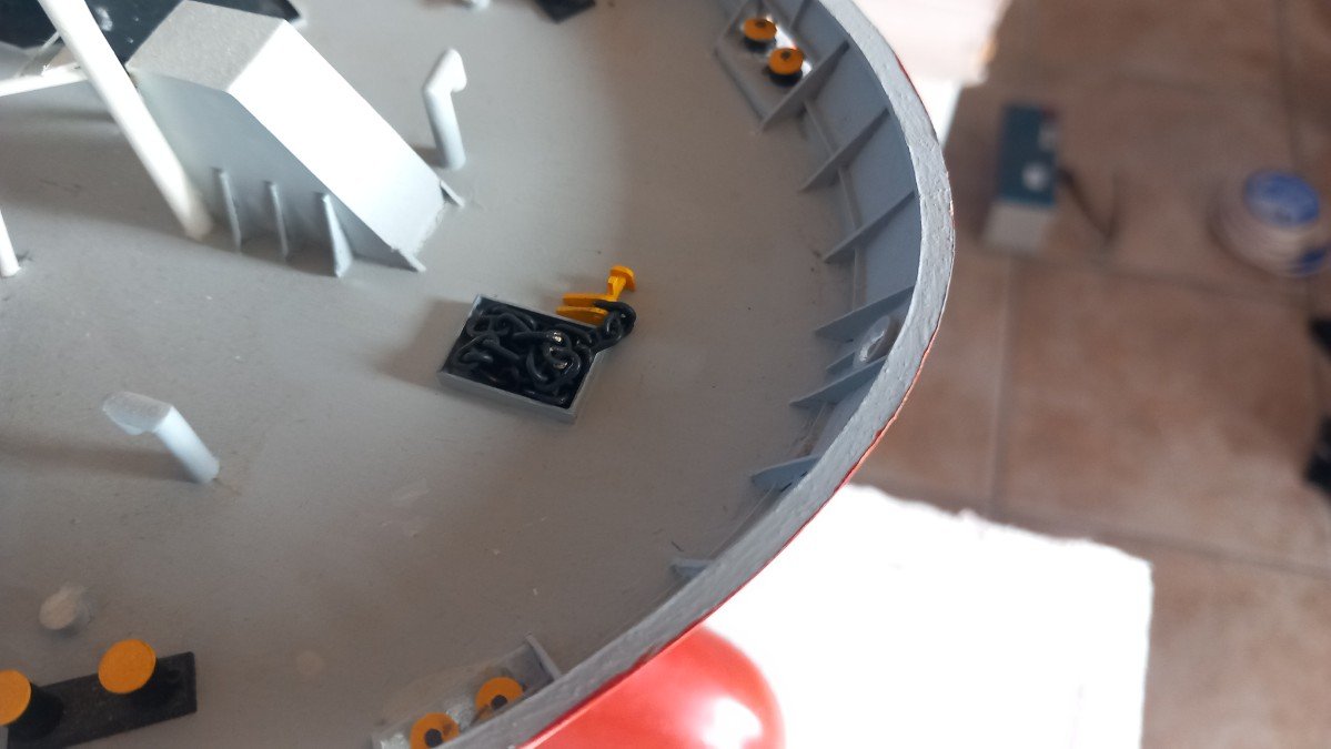
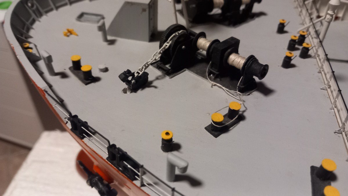
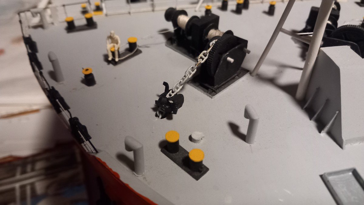
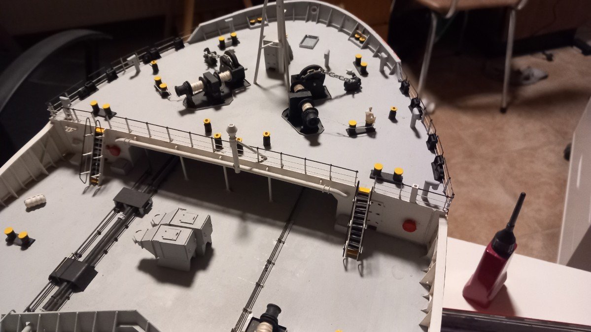
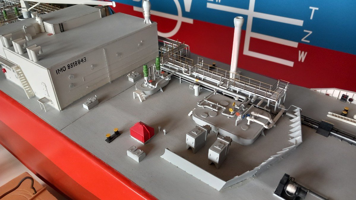
I'm really short of time nowadays, so not much progress. Also wanted to add pics of the real ship, but having some hardware issues, so I'll just show some progress pics. Started by painting (and currently mounting) the forward catwalk. During the painting process I decided to finally continue that forecastle. First was the Chafing Chain. It's part of the obligatory Emergency Towing System of tankers. Small tankers only have one forward, larger ones also have a system aft. The forward system consists of a Smit Bracket (yellow thing in the pictures), with a chain connected. In an emergency, the chain is led overboard through the Panama fairlead by either the tanker's winches or the assisting tug's winch and then connected to the tug for emergency towing. Due to a chain's strength it survives the chafing of towing in heavy swell etc. Steel wires aren't so good for that and wires deteriorate much faster than chains. The heavy chain was connected to the bracket and stowed in a small coaming. On most ships it's also covered with canvas, but invariably it ends up as a pile of rust... I also still had the chain stoppers to do. They transfer the forces of the anchor and chain to the vessel structure rather than keeping it on the winch brake and/or gearbox. I've seen about as many versions as I've seen windlasses, so no real standard there. Generally it's a big block that's hinged between two shackles of the anchor chain with a counterweight to aid in removing it when the anchor is hoisted again. Once it's in place, the chain is lowered so that the next shackle rests on the stopper block (transfer of forces, windlass loses tension). I also finished the stairs to the forecastle, first stairs to be finished in over 5 years!
-
I may have missed something, but in the pictures, I only see black smoke being emitted from the main funnel. That would be the exhaust of coal being burned in the boiler. I do not see any white steam being emitted except from that small pipe in some pictures. That said, with such small space, placing a condenser etc. wouldn't be very practical. On the other side it would require a lot of fresh water stored in tanks... All in all, a very fine build! Love that subtle weathering, a difficult task at such scale.
- 457 replies
-
- 5
-
-
-
- sternwheeler
- Hard Coal Navy
- (and 1 more)
-
Seem to have missed this. Glad to have been of any help on this build. She truly came out gorgeous! Despite your issues with the sails, I'm happy you went through and added them. The outcome has a great array of colours and contrasts. Although today they are generally engine powered, from time to time you still encounter some under sail in the Gulf.
- 65 replies
-
- 2
-
-
- sultan
- Artesania Latina
- (and 2 more)
-
Hi Brad, how much does she weigh at the moment? And I noticed decals on your air det, aren't you scared they'll come off in her wet environment? Or do you varnish the whole plane when they're finished? Overpowering a model is easy, but it's also necessary. Wind nor water scale down and nobody's going to make any mooring manoeuvers in an 11Bft gale... That said, seems like a fun boat to run. Not too large nor heavy.
- 51 replies
-
- 2
-
-
- Puncher
- escort carrier
- (and 1 more)
-
Great job and I'm happy you decided to install that rigging, it really adds to the stunning result!
- 288 replies
-
- 8
-
-
-
- Card
- Pre-Dreadnought
- (and 3 more)
-
They sure loved round holes.... Beautiful job on one of these handsome ships. Loving every post of your build log!
-
Having much less power astern than forward is quite normal in real ships as well. Propellor shape and pitch are optimised to move ahead, not astern. The main reason a rudder manoeuver is always preferred over a telegraph one. The turning radius is always much shorter in advance than a straight stop. Also reversing props makes you lose any rudder effect/use. That's why sailing isn't as easy as it looks, you need to look well in advance. Real ships also have a lot less power available than any model. That said, I understand that on a pond a short stopping distance is preferred, certainly when other ships are involved.
-
With two identical props you will have a stronger propellor effect when reversing. With counterrotating ones this balances out. Depending if you go for right or left handed props, the bow will very strongly move to either port or starboard side when reversing. Which then means that whenever you'd want to reduce speed, you need to take into account a heading change and turning of the vessel. Rudders don't work when props run backwards, so you can't compensate for it either. That's the only disadvantage I can think of. Perhaps also vibrations that will increase instead of cancelling each other out, but that's difficult to predict. She's looking sharp!
-
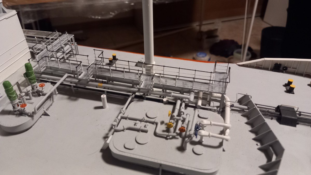
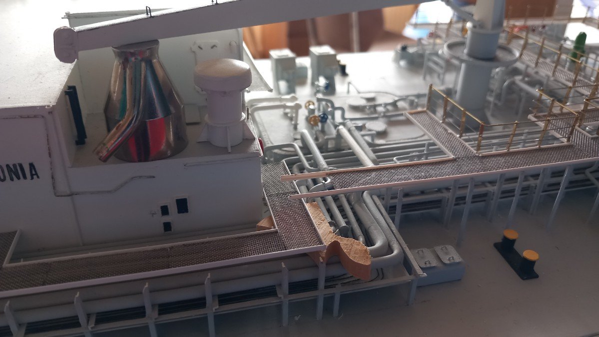
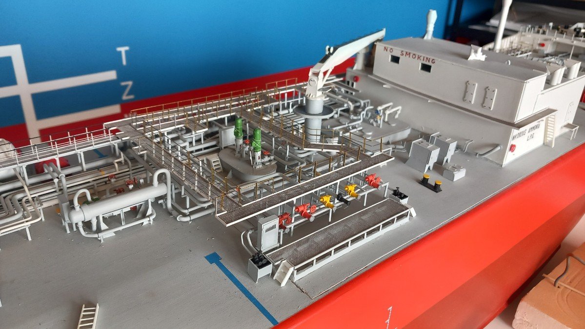
And time for an overview: next steps: - fix some issues with the piping edges at the forward edge of the hatch and piping issues forward of that edge - level out forward catwalk since it determines the height of the next part along the deckhouse - complete the piping connections to the deck house - finish and fix catwalk next to deck house - finish forward edge of manifold catwalk where it makes a step to the part next to the deck house I believe after that that I will proceed with finishing the deckhouse (finally put the real crane jib support in place instead of an airbrush jar) and railings on top of it. And together with that, start making the stairs to the catwalks. Only the aft catwalk is glued, all others are just dry fitted. I will first put some transverse beams, paint those and also the catwalks themselves before gluing them, same sequence as I used on the aft part.
-
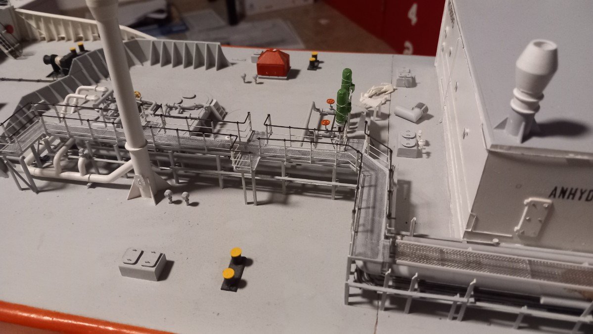
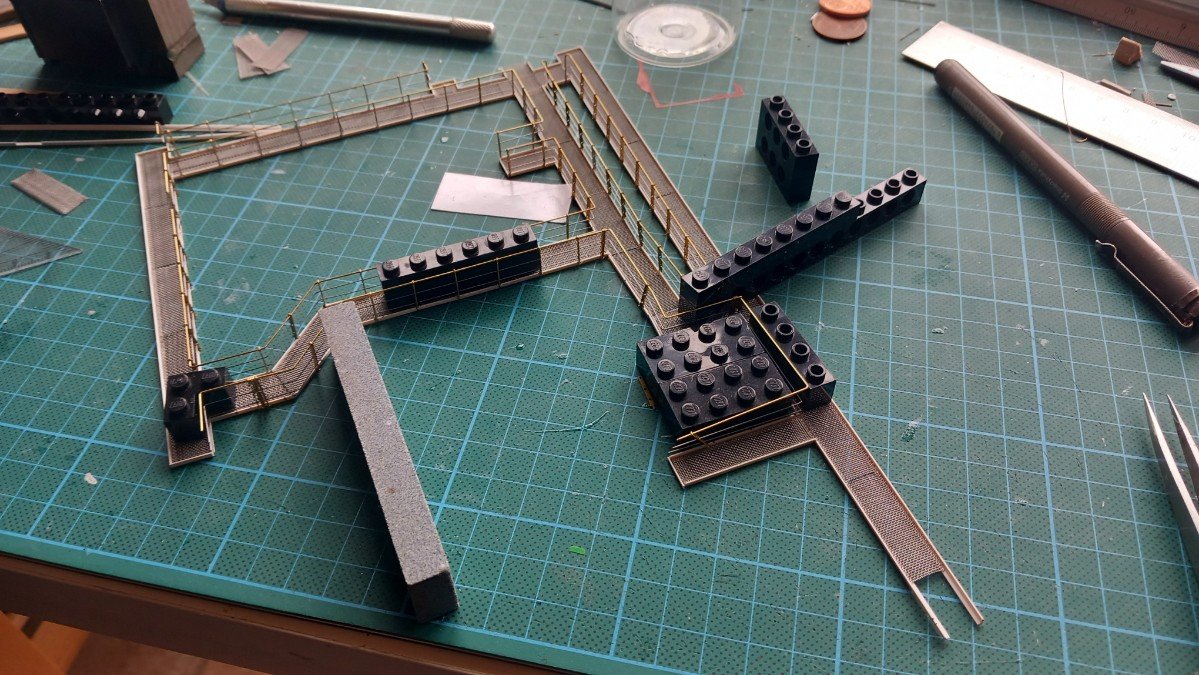
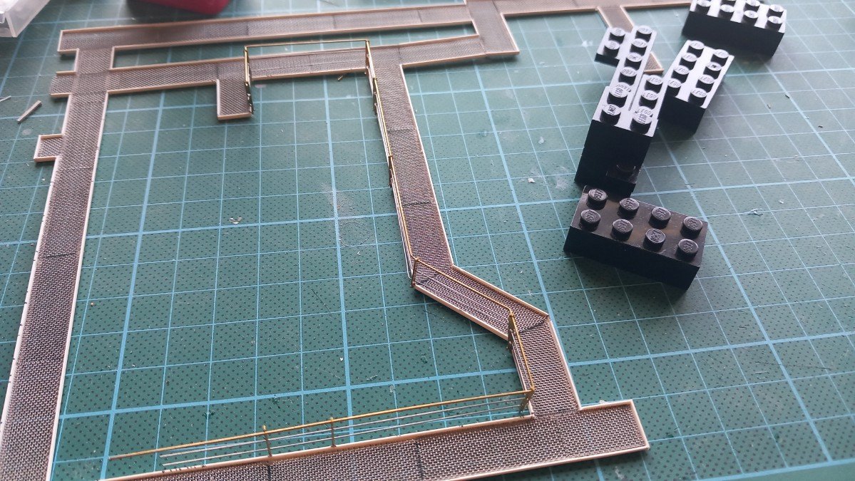
I did not have much time in the last couple of months, but did manage to do more than anticipated the last two weeks. I haven't made any updates since it's simply more of the same... I finished the forward part of the catwalk, including railing. Currently working on the railing of the manifold part and simultaneously building the last part of the catwalk, the part around the deckhouse. As you can see, the Legos have made an entry for keeping things in place and straight. Picked up that trick over here. Of course I need to be carefull since I'm using glue for styrene, so I don't want to glue the blocks to the catwalks...
-
For what it's worth, the bearing device is called a pelorus. The stand itself is called a binnacle or compass/gyro repeater. I'm however not certain if in that time they actually had repeaters or if it was a fixed rose that would give relative bearings (relative to ship's bow that is) rather than compass bearings. Nowadays we take gyro bearings with these things. Sorry for interrupting. You're doing an excellent job. Quite an improvement over your original version!
-
Fantastic job on that paint! Something to be truly proud of, certainly if you're not used to do such things. I wouldn't even know how to get started on something like that. (well I'm a bit closer due to your explanation)
-
But the question is: what about the moss-idea??? Loved the Zen garden too, but as mentioned before, it would probably take some of the focus away from the bottle...
- 106 replies
-
- 2
-
-
- Kentoshi-Sen
- bottle
- (and 1 more)
-
Haven't been too active around here, but a great job on this SIB Glen. I'd also go for the second one, however I'd try to crudely break off the left part that sticks out towards the front. This would create a more compact contour. Love the moss idea as well, but it's up to you, the "hard line" doesn't really bother me, but the moss would add some colour.
- 106 replies
-
- 3
-
-
-
- Kentoshi-Sen
- bottle
- (and 1 more)
-
Late as ever, but you can count me in! I'd say that small pipe is an overpressure vent from the boiler. Based on the white colour of the smoke in your last picture as well as the fact that she is manoeuvering with that barge near the quay in that picture. She'd be reducing and/or reversing her engine at that time, which would create an imbalance with the steam production/consumption in the boiler. In those first pictures, she's made fast on the bow, but keeps pushing forward against the quay to keep her in position, which would create a steady steam balance and no need for venting any overpressure. Just my 2 cents, I'm not a specialist on steam systems of that age. I'll be happy to follow this build, lots of opportunities for weathering!
- 457 replies
-
- 4
-
-
-
- sternwheeler
- Hard Coal Navy
- (and 1 more)
-
Not exactly my subject of choice, but I recognise a professional at work! I'll simply follow along with great admiration because of your professional approach, workmanship and tricks. Great and very sharp construction!
-
"Astonishing" is all I can say. That last picture with your duckgratings in place really looks like the real thing. That weathering is brilliant. It's only the lack of finer detail in that picture that shows it's the model in progress rather than an example of the real thing!
-
USS Constitution by mtbediz - 1:76
Javelin replied to mtbediz's topic in - Build logs for subjects built 1751 - 1800
I second what DAR said above. She's looking brilliant.
