HOLIDAY DONATION DRIVE - SUPPORT MSW - DO YOUR PART TO KEEP THIS GREAT FORUM GOING! (Only 75 donations so far out of 49,000 members - C'mon guys!)
×


Javelin
-
Posts
625 -
Joined
-
Last visited
Content Type
Profiles
Forums
Gallery
Events
Everything posted by Javelin
-
 The question is, does the veering off course happed due to wind or simply due to minute differences in the oars? If it is the latter, you might add a longitudinal skeg on the bottom, the length of the keel. This would make her more "course stable", however it will make her less manoevrable as well. I don't really expect a real issue when really turning on the oars though. The rudders will have even less effect if you do this. It could however reduce the veering off-course. On the other hand, if she just gets blown sideways, this will not help too much. If it's of any comfort at all, I'm also having issues with the wind on Chaconia, I really need a big calm pond to sail it as she doesn't have a bow thruster and the turning with the wind gives a very large turning radius.
- 536 replies
-
- 3
-

-

-
- Quadrireme
- radio
- (and 1 more)
-
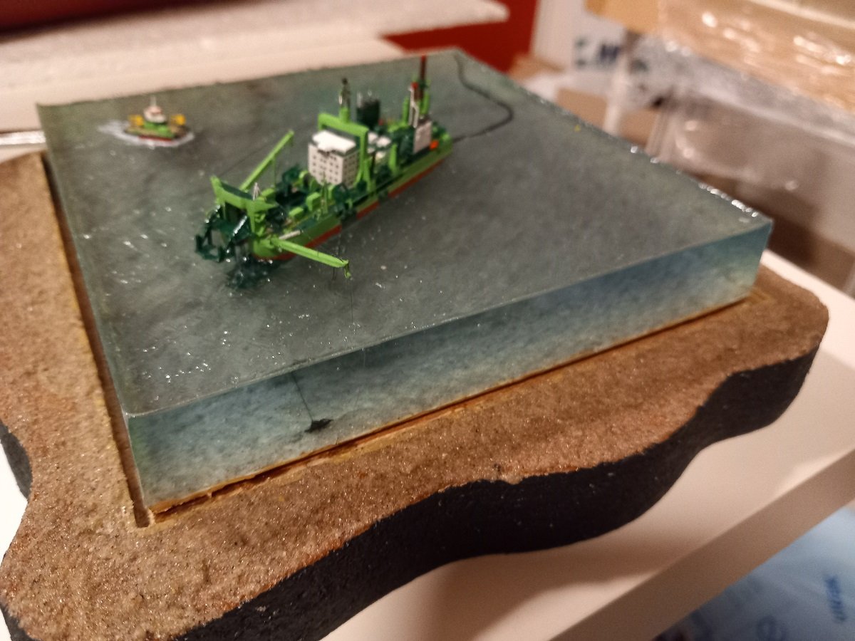
Mr McGuire that's a brilliant piece of water. Great call on the grey wash between the layers!
- 235 replies
-
- 5
-
-

-
- Banshee II
- Bottle
- (and 1 more)
-
Well actually... This is quite normal on workboats. Tugboats nowadays can work both directions, some even have 2 sets of portside and starboard side navigation lights to shift. On cutter suction dredgers it's also often like that (Spartacus being an exception to that rule, having her gantry forward). They use "navigation SB/PS" and "dredging SB/PS" or just SB/PS for regular vessel and left and right for dredging direction. On top of that, there is an icebreaker called Baltica that has an assymetric hull and breaks the ice sailing sideways That said, great job on this pile driver and the boiler Keith. Making great progress. Curious about the supporting vessel already.
-
Very sorry to hear that Ian. Not unexpected though, normal rudders on ships also hardly work when the propeller is stopped, regardless of the speed the vessel is making. The skeg idea is unlikely yo work though. Ships rotate around their pivot point, which, at full forward motion, lays around 2/3 forward of the stern. It is the point that makes a circle in the water, yet the vessel rotates around it. When stopped, that point moves to the center, when moving astern, the pivot point moves astern of the center. So moving forward, the rudders have a very good mechanical moment/arm to rotate the vessel (but bow thrusters are limited in effeciency to a speed where they become truly useless). When moving astern, a rudder is almost useless, but a bow thruster gains in efficiency. Adding a skeg midship is not going to change the behavior of the pivot point. I believe enlarging (clip-on perhaps) the rudder surfaces or angle might be more beneficial. Regardless if everything is on scale, unfortunately "water" does not behave on scale (Froude number et.). That's also the main reason manned models for navigation courses are in scale, but prop and rudder are way out of scale to get to a realistic manoeuvering characteristic. This is not to discourage you and if you can test the skeg in an easy way, I'd be happy to be proven wrong. I just don't want you to have too high expectations of that solution and encourage you to think of plan B and C to get this to work. She does look awesome after all!
- 536 replies
-
- 5
-
-
-
- Quadrireme
- radio
- (and 1 more)
-
Thanks for the clear explanation. Even if the waves/ripples wouldn't hide creep up, for sure they'll merge the front pilings with the water surface. A very sharp result and good reference for future projects.
- 235 replies
-
- 6
-
-
-
- Banshee II
- Bottle
- (and 1 more)
-
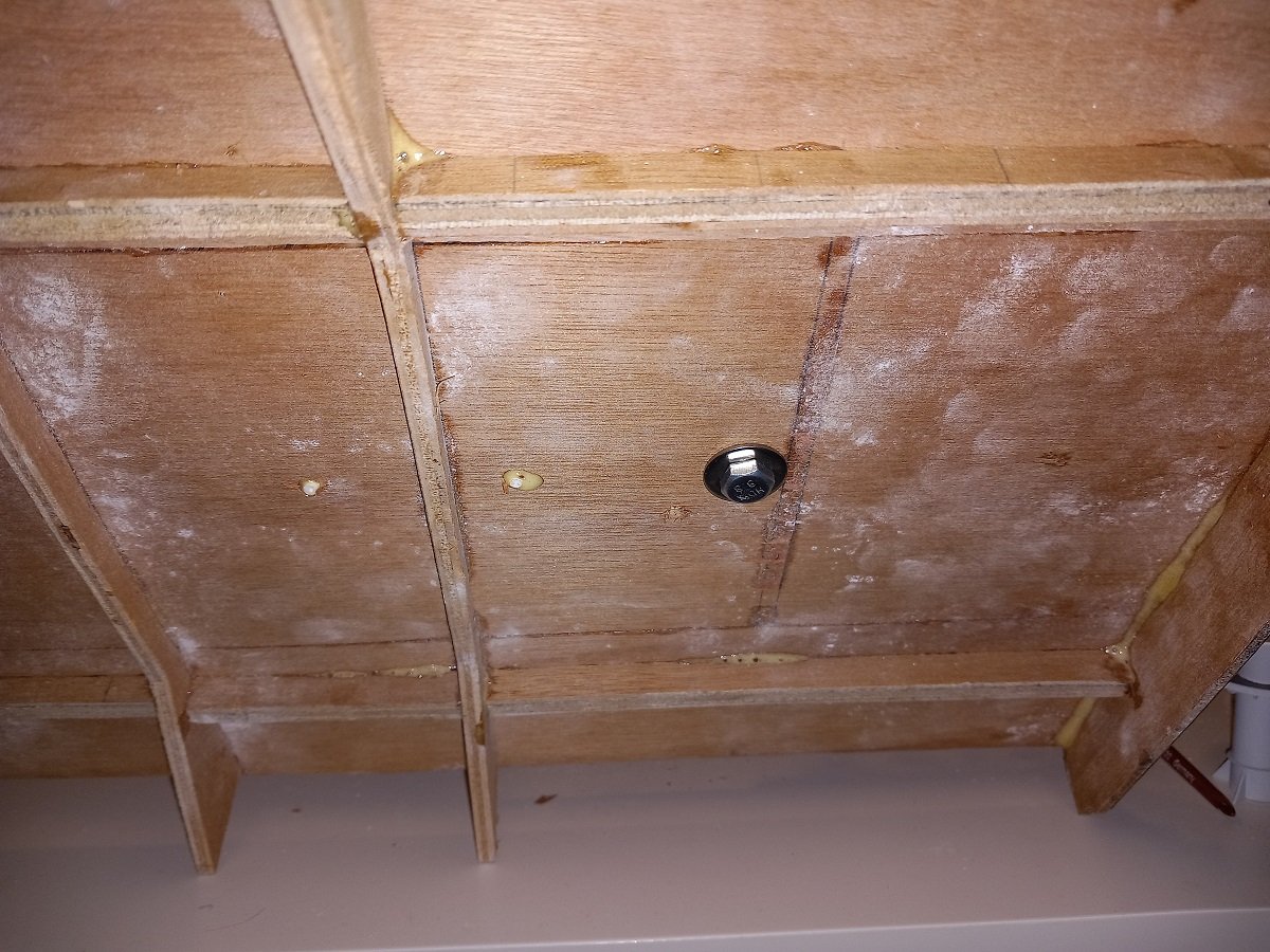
Those front pilings are a great solution to the creeping epoxy, but how did you fix them? Drill a larger hole and then used some epoxy glue? Or is it simply a tight fit and did you only glue the bottom of the piles? And does the epoxy glue you normally use also have a tendency to creep up? Great job overall. Looks very sharp.
- 235 replies
-
- 6
-
-
-
- Banshee II
- Bottle
- (and 1 more)
-
Incredible work Igor. I wouldn't even know how to start something like this. I love the way you pour the epoxy early on and add partially submerged objects later on.
-
You have your first follower. Just a minute ago I posted in your Alert log and my curiosity is already satisfied. If this will be even just near your Alert quality, it will already be a very impressive model. That said, it's going to take a while to complete, since scratch building is going slow, but so much more satisfying for the builder.
-
What a great result. Nice to see what can be achieved from a kit. Yet as a first build, this is pretty awesome. That paint job on the stern and sharp rigging really make it stand out. Curious about that next build as well!
- 562 replies
-
- 3
-
-
-
- vanguard models
- alert
- (and 2 more)
-
I believe @KeithAug is talking about stability rather than keeping the ship level. Indeed with such a small beam and draft I also thought this would be tricky, considering the height of that tower. On the other side, the center of gravity and weight of the pile wouldn't be that high up... The machinery above deck doesn't help much though. Interesting concept in any case. Great job on the build so far. Love the choice of wood, the colours are really matching.
-
One of the SIB masters has returned! Your builds are an inspiration and I'm happy to see a new build. Great job so far.
- 51 replies
-
- 3
-
-
- LAK
- St Nicholas
- (and 2 more)
-
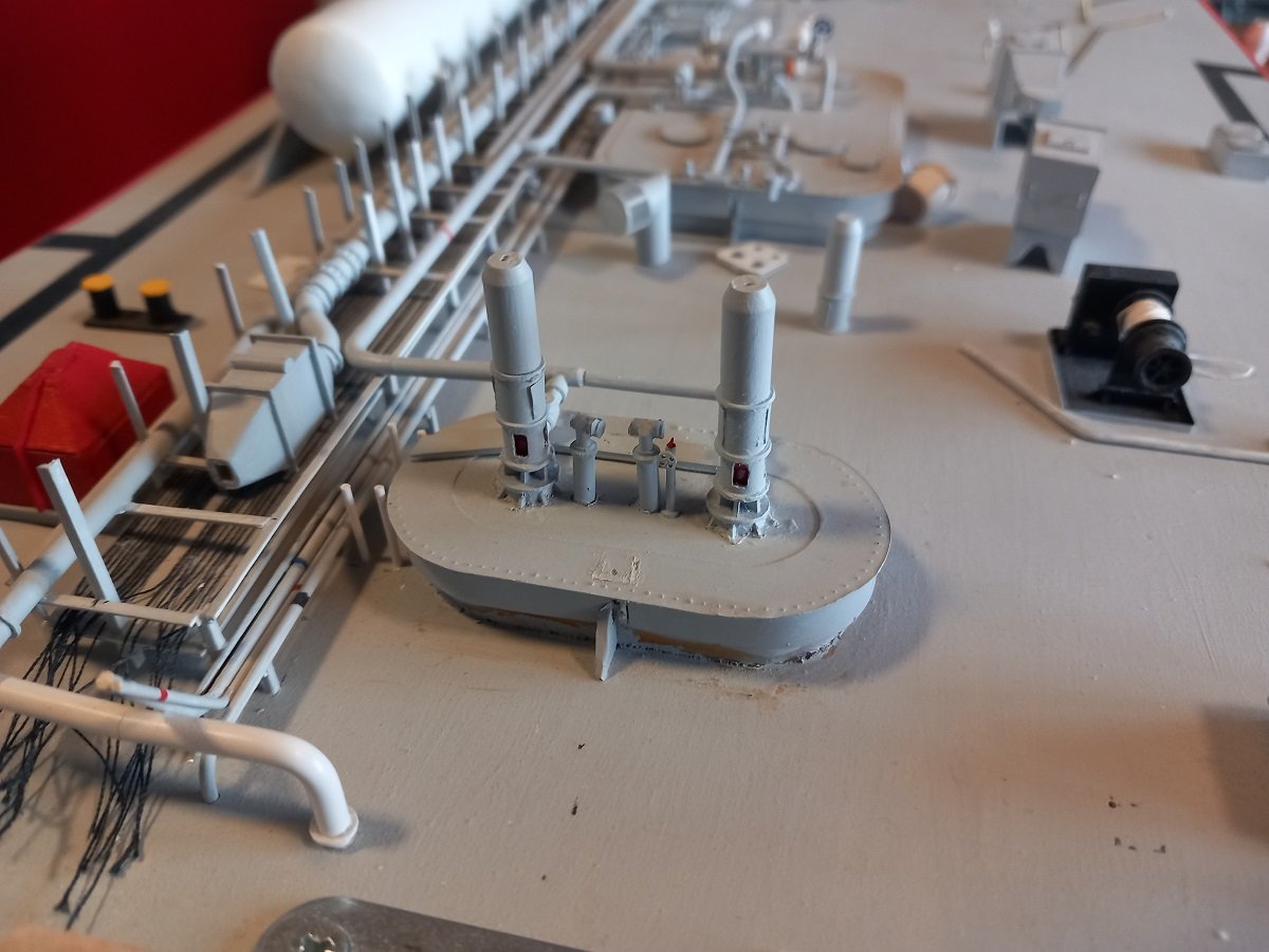
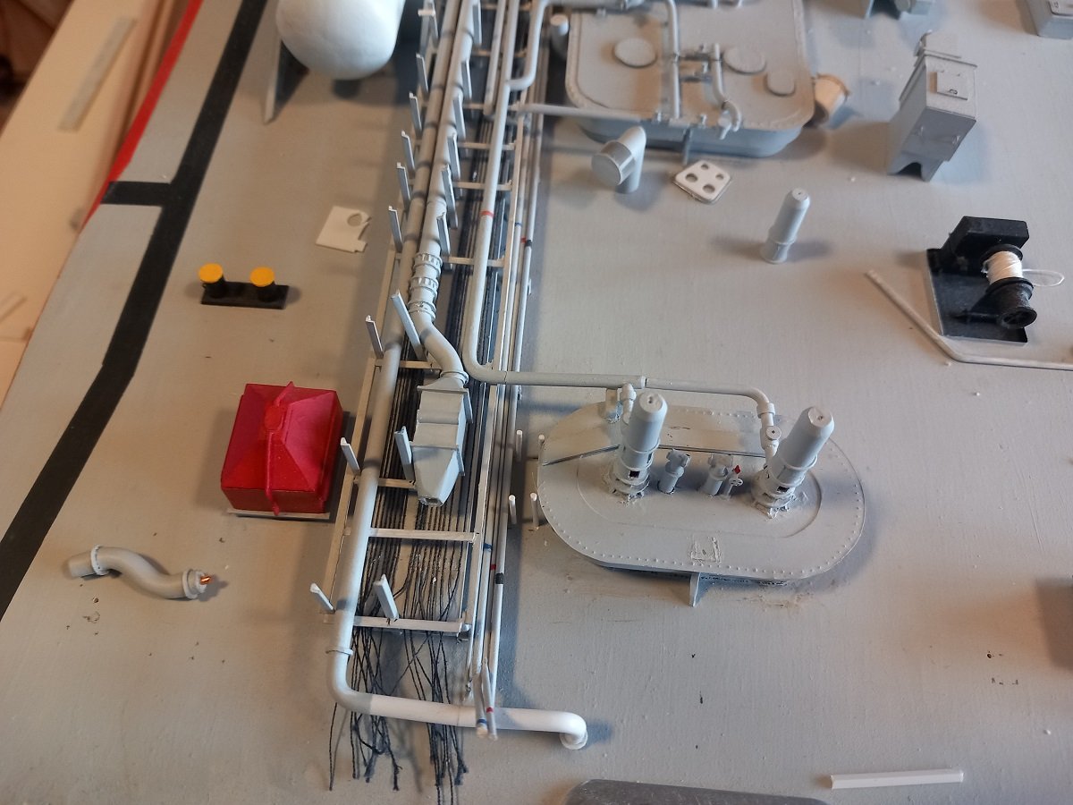
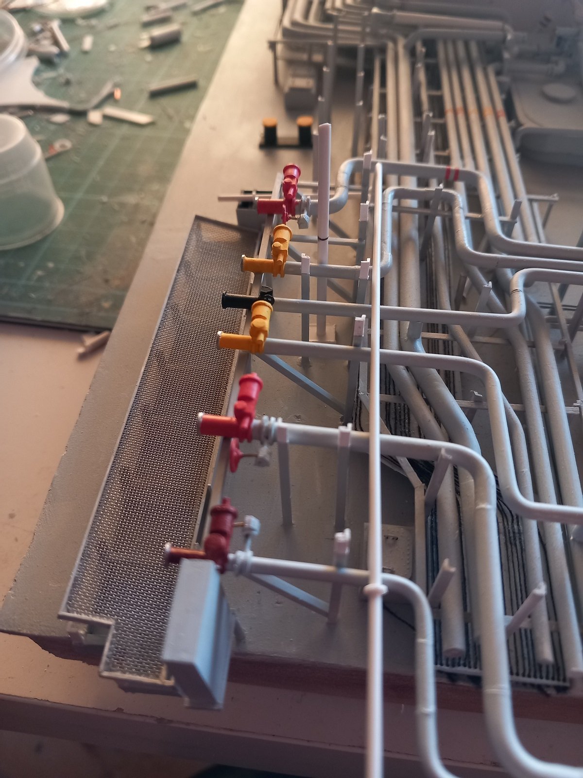
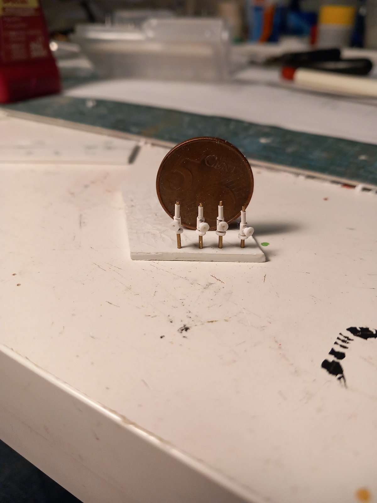
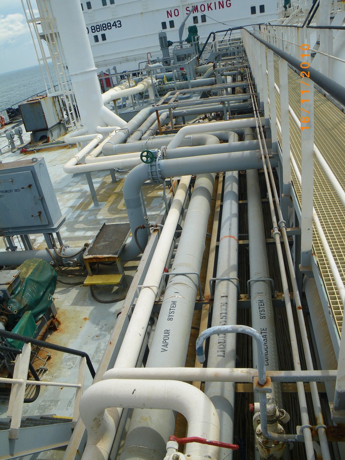
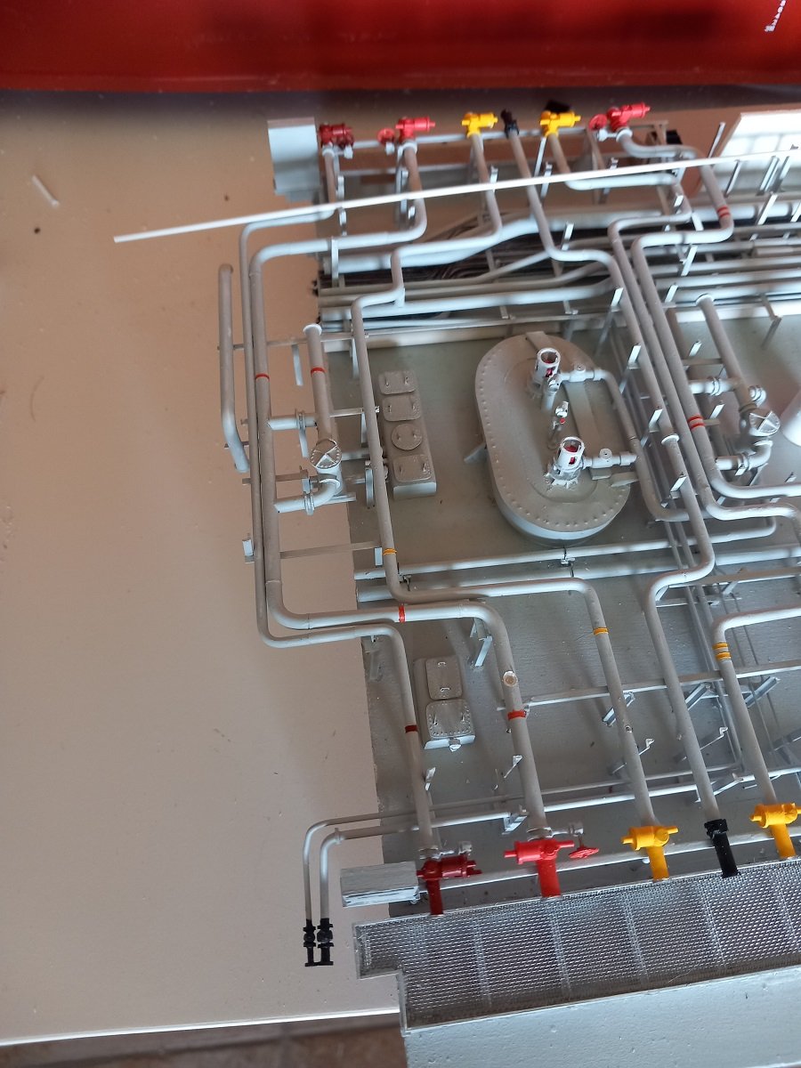
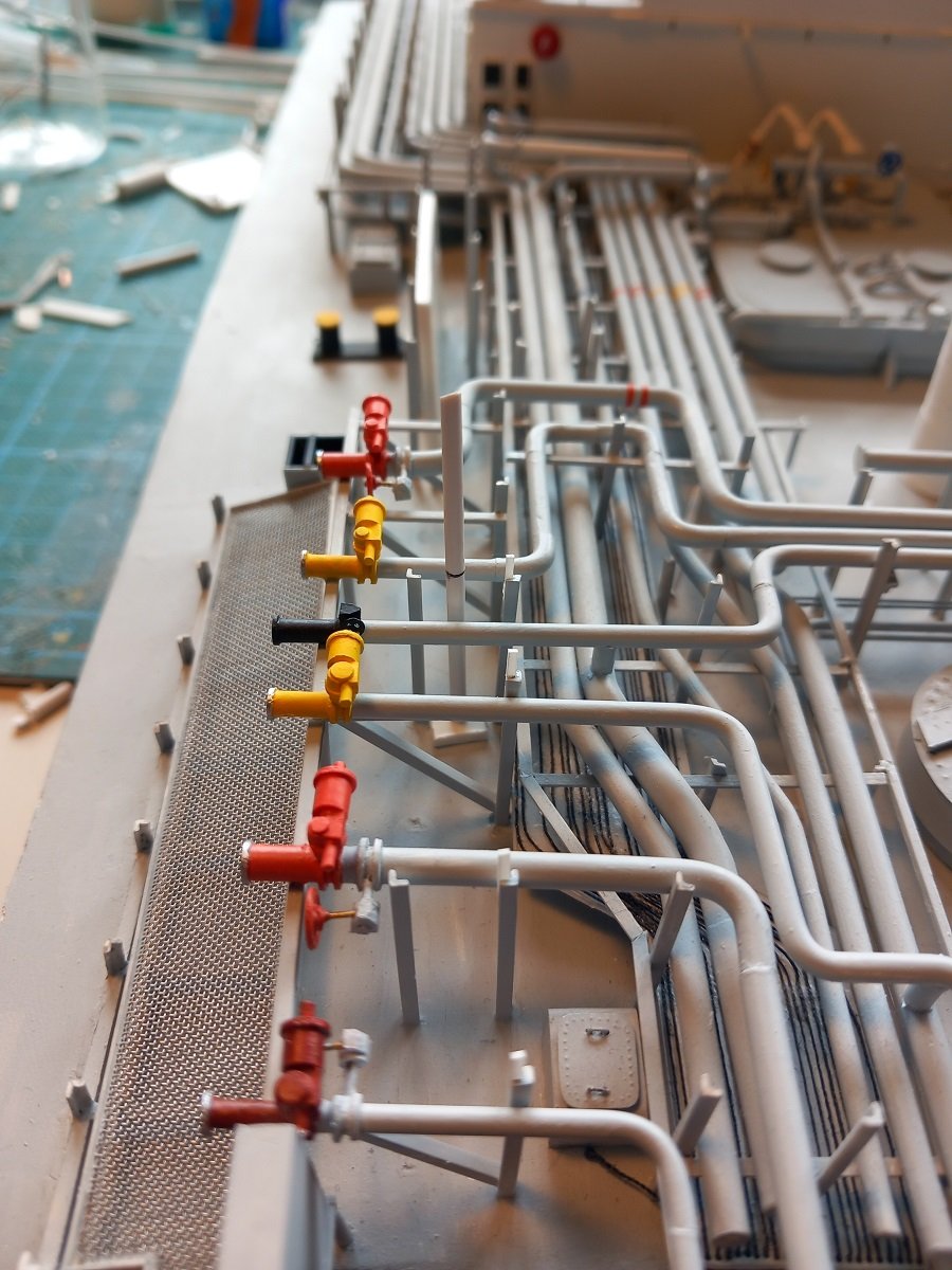
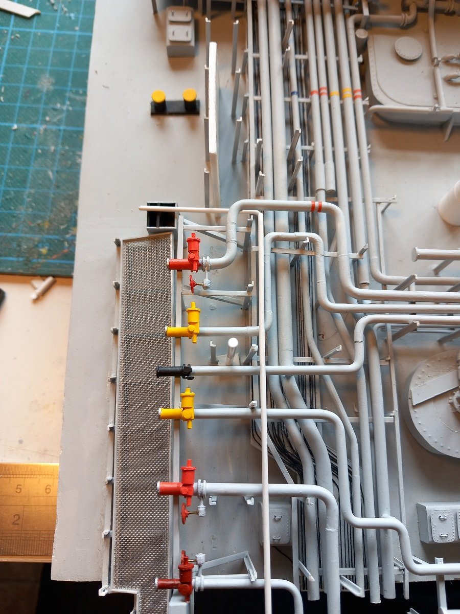
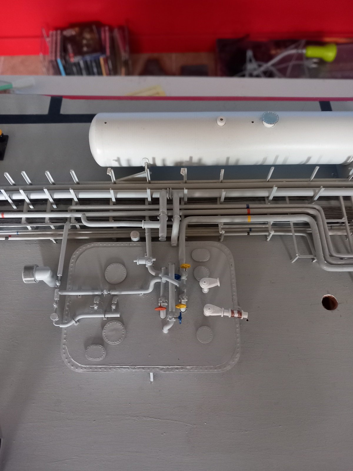
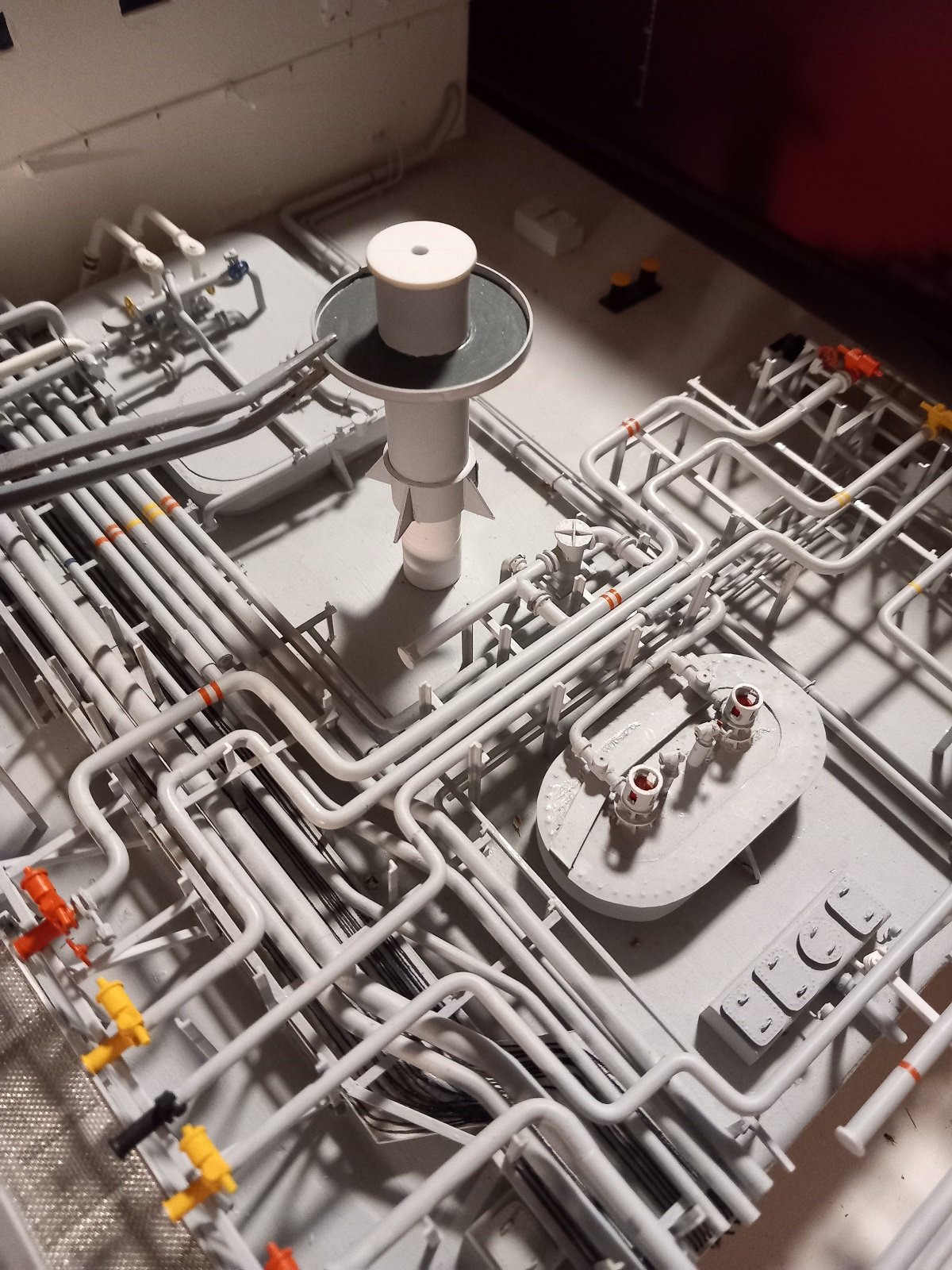
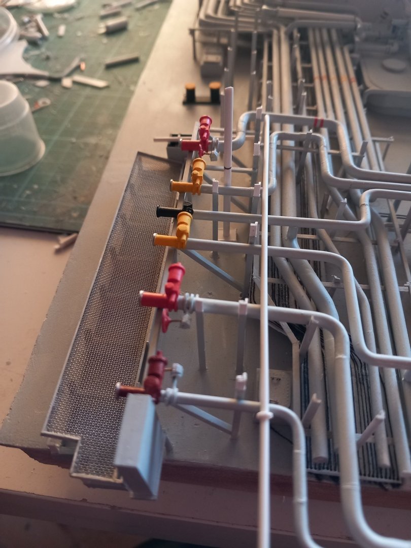
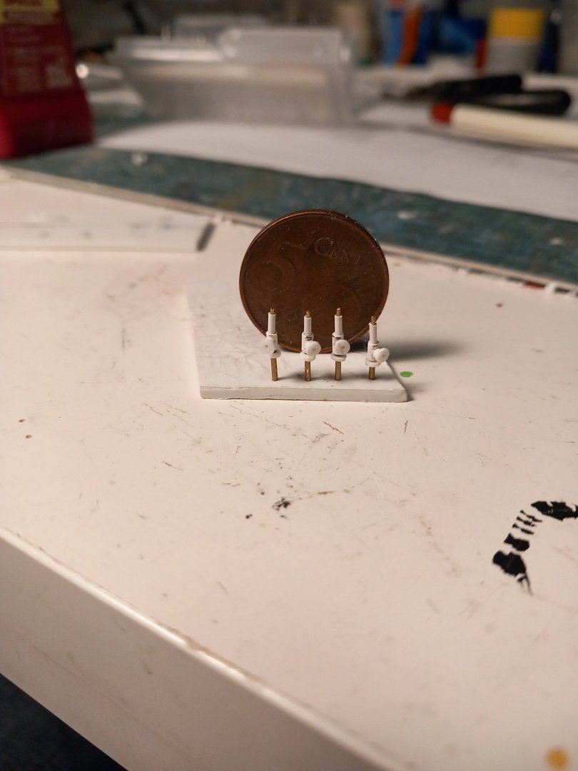
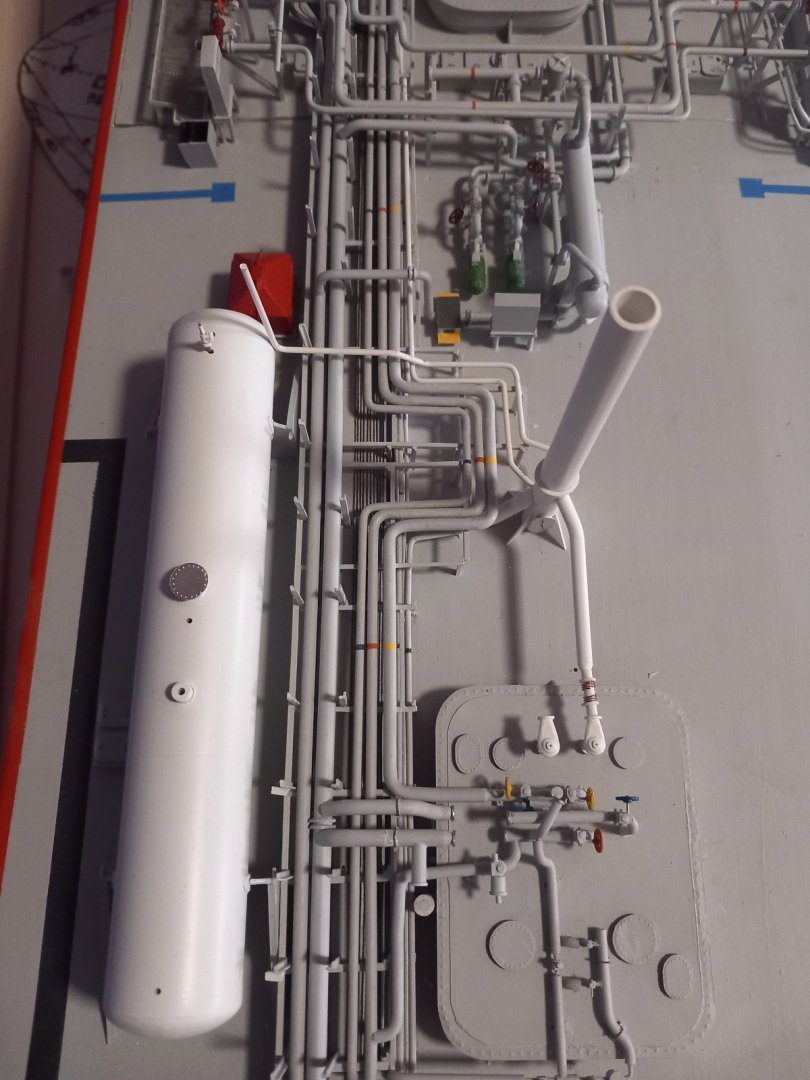
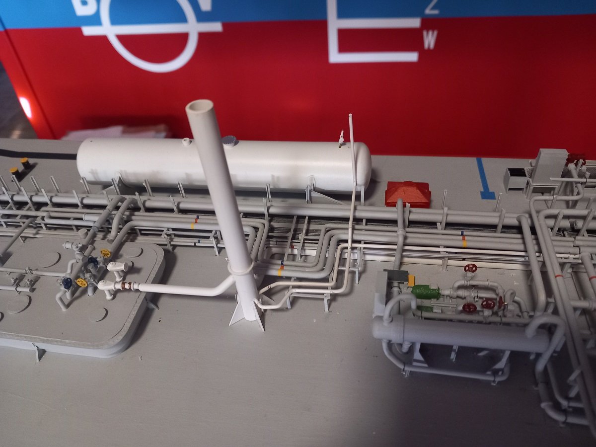
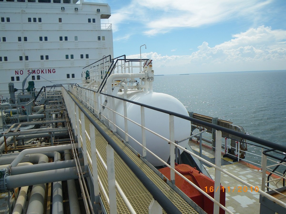
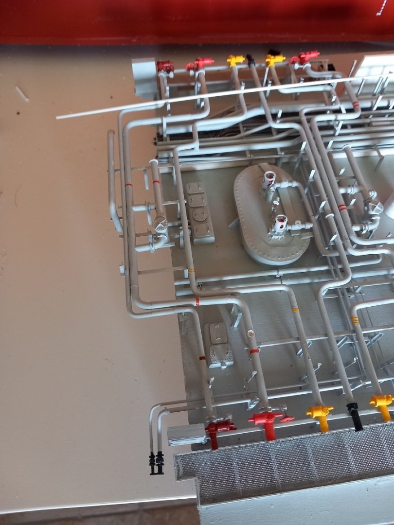
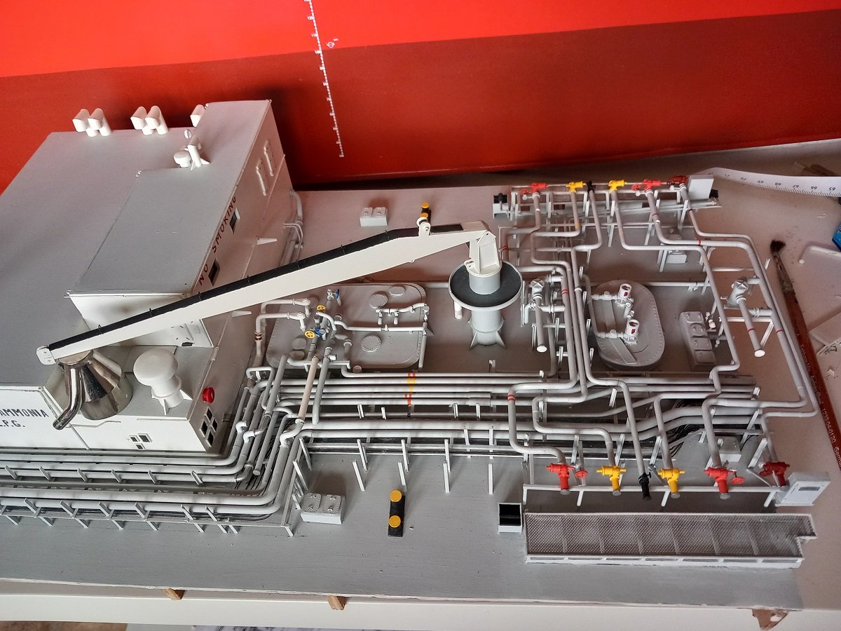
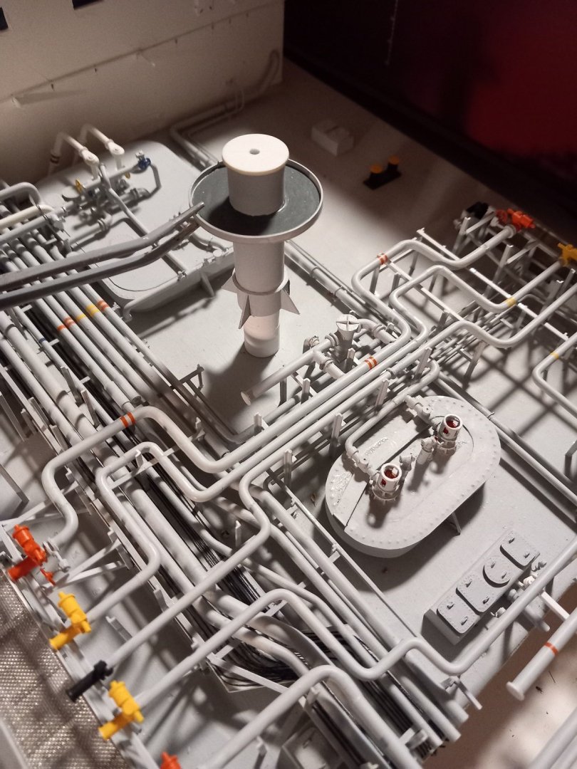
@Glen McGuire, @Rick310 and @KeithAug, thanks for the comments. Everyone thanks for the likes as well. Keith, I'm not exactly sure... After sailing on those gas carriers I went to dredging. There's a lot less pipes there. On the other side, they are much much much larger, so I'm not sure if that means I'm in rehab or if it's getting worse. In any case, I guess what comes next will confirm your verdict. It's the voices really, can't argue with them... So what happened next, well, progress wasn't exactly as fast I imagined it would be. Mostly due to garden chores and summer holidays for the kids. However, I got to a rather complex point. I installed the extensions of the stanchions and that portside bunkerline (part of it anyway). Aparently I didn't take a picture yet of the finished thing. I'll do that soon. However, I wanted to finish that bunker line with the aft part (mounted on the fixed part of the ship, not on the hatch, when I figured out I had to cross some lines etc. That's where I found out I had to cross the safety line. That's basically a line that connects a whole bunch of overpressure valves to the vent mast. Each piece of pipe that can be blocked in between two closed valves is required to have such a valve mounted on the pipe. They are small, mostly spring loaded, valves that relieve the pressure when the closed-in liquid or vapour starts to expand by temperature. Whatever that is released is sent either back to the tank or to the vent mast. I was not really intending to build it when I started this build due to its complexity and varying sizes. I was also "allowed" to leave that decision for the future as it's location is on the outside of the pipe rack and it would therefore be possible to add it later... That said, I guess it wasn't possible to postpone that decision anymore and something would definitely look amiss if I left it out completely. It's a rather large line and it's painted white, a nice contrast with all the grey around it. So off I went. Here's a picture of the real safety lines. 1 is the long one, the other crosses it and comes from the deck tank overpressure valves. And the deck tank with its safety valves. So I decided to start with the hardest part, some overpressure valves/ safety relief valves. These are just dry mounted, flanges and valves aren't yet glued to the brass wire below them. I decided to only partially install the safety line on the vessel. At least it won't look like something's missing, it just won't be complete. These safety valves are the largest onboard, all the others are 1 or 2 sizes smaller and would be very difficult to build properly. And then came the lines themselves. Haven't completed them yet, but it looks like it's heading in the right direction. This however also forces me to paint and fix that aft vent mast in place, something I'd prefer at a later stage as I still need to work in that area for the deck tank piping and catwalk. That said, it is what it is and I'll have to work around it. She's slowly getting as crowded as the real thing by now.

-
Great job Glen. That funnel was soooooo recognizable. Twisting stuff in tweezers by very slightly releasing your grip until it's just enough, or it just drops out Those side wheels were a nice example of my earlier statement, working out of the centerline with tweezers isn't easy. You can't align pieces with the ship when your tweezers are under an angle from the centerline. You did handle that nicely though. Second funnel really went smooth. Awesome job overall !!!
- 235 replies
-
- 5
-
-
-
- Banshee II
- Bottle
- (and 1 more)
-
Very impressive build. Echoing the above, the crew really brings it to life. The sharpness of your construction keeps amazing me! Splendid work!
-
Good to see another project. Work boats allow for so much more to show than regular navigating ships. They interact a lot more with their surroundings which kind of forces you to build the environment and show their main activity. I'll be following along to see where you are heading with this one!
-
That sure is a challenge. Setting the bar higher once again. Assembly into bottles is much underrated given the blocking effect of the bottleneck on tweezers.
- 235 replies
-
- 5
-
-
- Banshee II
- Bottle
- (and 1 more)
-
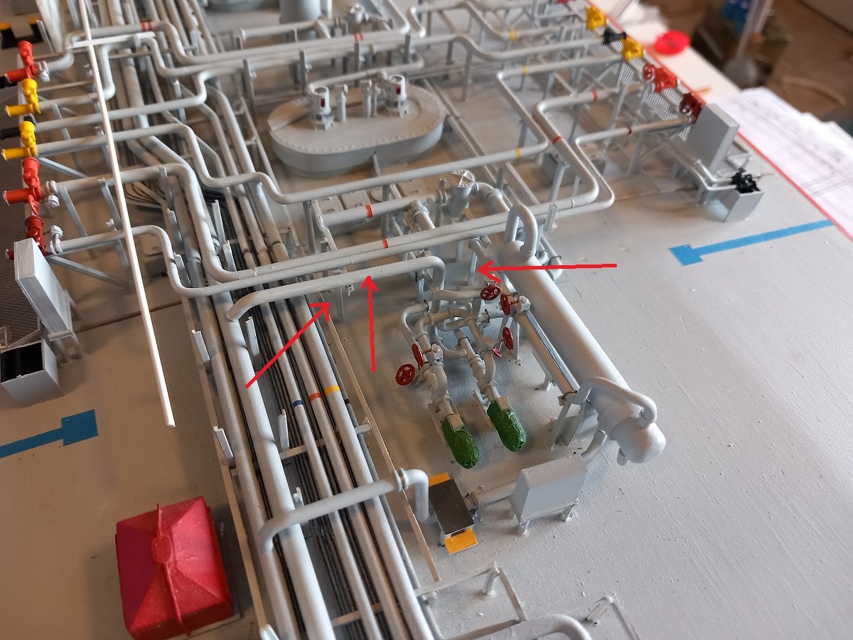
Well @Ian_Grant, that layer is actually not that much. Sounds like a complete layer, but all in all it's just the bunker line on PS of the manifold. It runs just on top of the cargo piping and therefore represents a "layer". On the rest of the vessel that layer is not present. There is one more layer and that is the deck tank piping, this runs over that PS bunkerline and therefore is considered a new layer (by me). So sounds like a lot of work, but all in all the piping is mostly done. I also still need to connect the cargo piping to the deck house, which is probably going to take me a while as well. In the meanwhile I've been stalling over those stanchions... Finally finishing my Spartacus diorama didn't happen by coincidence last week. I really did not look forward to extending all of those stanchions and was really upset that I could have avoided this from the beginning. I did however discover how it happened. I started with those stanchions on the fore part of the ship then going aft. I forgot that there is a step in the catwalk just aft of the deck house. This also means that at least all those stanchions next to and in front of the deck house won't need extending (yay). That said I needed a grip on this issue and get a hold of a starting point. I started with some left out supports on the aft part of the manifold. They had to be built top-down since they'd be hanging over the edge (see pics below). Those stanchions were attached to the piping on top and then I had one hovering pipe that was halfway supported by those supports as well. That one needed to be placed first as the PS bunkerline is adjacent to it. That bunkerline, along with the deck tank piping are the determining factor for the minimum stanchion height for the catwalk. So that was my starting point. I put some arrows in below pic to show the new parts as nobody would probably figure out what was new and what wasn't... I didn't mark all of them, but you get the idea. As mentioned it's a hovering part, a lot of installing and removing of the hatch. It also forces me to adjust the edges as I still have occasional collisions when installing the hatch and that should go smoothly. I must say this spaghetti does hide the edge of the hatch quite well. Then came the initial bunker line (unpainted, white) with its bends and the extensions. I decided to go the more labour intensive, but more correct way of making small strips that fit inside the L-shape of the supports. I will then add small lengths of L-supports to extend the originals. The other idea, which would have probably been easier was making inverted U-shapes and glue those in the edges of the supports without adding L-pieces, but it probably would look very odd. I then made a small measuring tool, a piece of 2mm rod with a marking (also carved) and a small foot to keep it standing. I then add the strips to the correct height. Later on the L-support will follow until I attach my bunker line. Once that is approved, I'll do the SB side supports and have a steady level to extend the rest in between. Bear with me, it's going to take some time. I'll probably do some jobs in between as well, like finishing those cargo pumps, adding wheels to the discharge valves of those pumps, perhaps do the deck house piping etc. to get some distraction from the tedious strip cutting and installing.


-
Great job again Glen! Very instructive. Continue like this and you'll create a whole horde of SIB builders over here!
- 235 replies
-
- 6
-
-
-
- Banshee II
- Bottle
- (and 1 more)
-
She's finally finished. I put some pics in the gallery. Thanks Mike. Hope somebody can learn from my experiments. I guess in most cases it's not such an issue since the epoxy stays in the sturdy box/bottle in which it is poured. I removed the bounderies, which was perhaps done too early, creating this bending. It's not a disaster as I could still hide it with the base, but I'll take it in consideration for future builds.
-
And finally found some time for the pictures of last week's work. Small reminder of that crane, not entirely finished, but gives an idea of how great an idea it was to use it as a handle to lift that hatch... Now on to the solution. I used a bolt with washer, M6, since I didn't really find an M4 in the store, and M6 would still fit after all. I then decided to basically do the same as my original idea, except that in this case the crane pedestal would be the cover of the assembly. This does mean I need to remove the crane for lifting the hatch, but I believe it's safer for the crane's integrity. Since the top and pedestal will be glued together and the jib will rest in the jib rest, the direction of the pedestal will be correct as well. Due to the relatively long piece below the nut, the crane pedestal will fit snugly on top and will not move when the vessel is underway. I had to machine that part a bit to make it fit, but it's now both tight, yet loose enough to comfortably lift the crane off. In the first picture, with the full crane, it's actually already mounted on top of the nut-bolt assembly. So in order to remove the hatch, I will now grab that piece of threaded bar to lift the aft side of the hatch. (still need to test that though). And finally I also installed the branches of the IG line towards tank 3, meaning that part is finished as well. Time to start extending all the stanchions for the catwalk. Not something I look forward to, but has to be done before going to the next layer of piping.


-
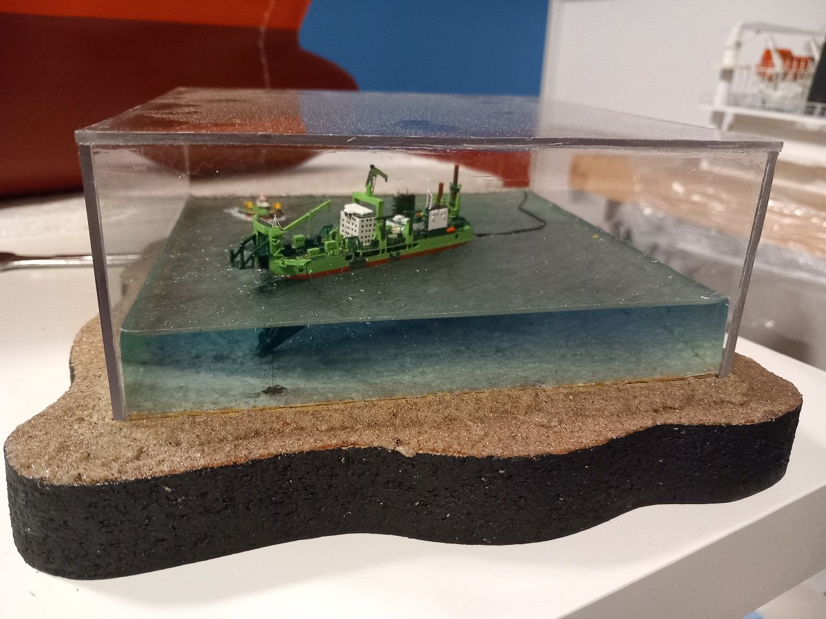
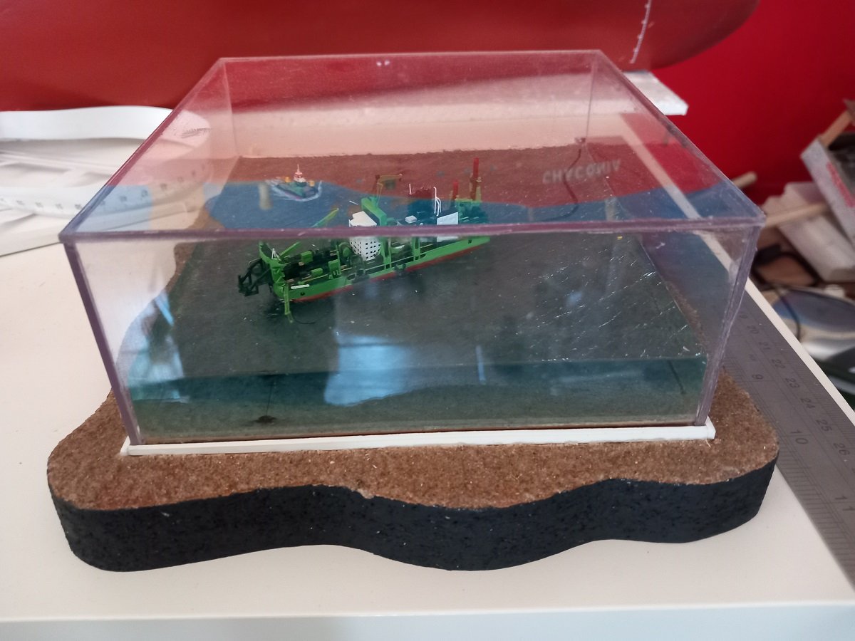
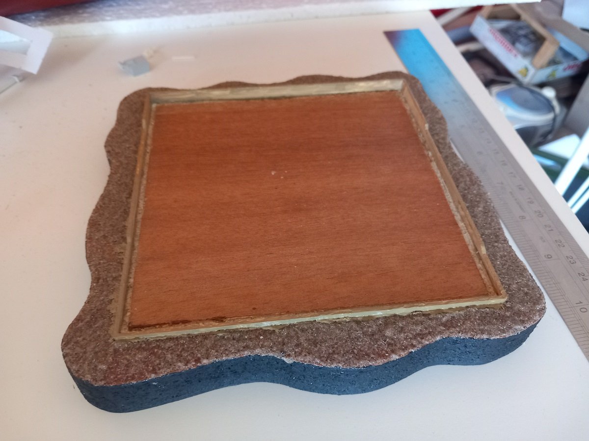
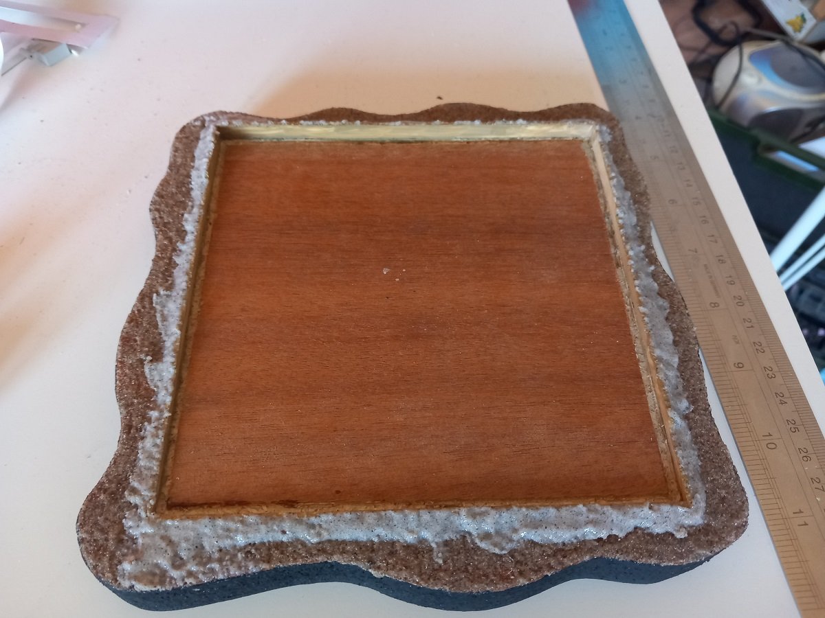
As you may have noticed, those last bits really are tough for me... Finally took a decision on finishing this one. As you can see in one of the last pics, the epoxy seems to have lifted the corners of the dio, not entirely sure where that shrinkage came from, since in older pics you can see it was nicely flat on the bottom. That said, I had a few options, one of them was to place the casing, then follow the edges of the dio bottom while applying acrylic-sand mixture on the casing walls. The other option, the one I actually used, was building up a border around the casing, with the border following the contour of the dio bottom and then filling up to that edge with acrylic-sand mixture. This option would be a bit more difficult, but would allow the casing to be removed (and replaced if required, not too happy with the whole thing, few glue accidents etc. on that case). So once it was decided to go for that border, I built it. Then painted the inside brown (ochre with some black) and applied a mixture of acrylic gel with ochre-black mixture. The reason for the difference is that I didn't want to put the sand/acrylic on paint, with the shrinkage of the acrylic, it might loosen the paint from the border. By mixing the paint with acrylic, it would be an acrylic-acrylic adhesion which seemed less risky to me... I wanted some colour on the border as I'm not sure the sand would cover everything, and with a white styrene background that would be too obvious. And then applied the mixture around it. And now the curved bottom is a lot less obvious and the case is still removable. I'm already a lot happier than before. One or two more coats of the sand mixture to blend the whole thing in and then a nameplate. I decided, with help from my better half, to cut a negative stencil to apply on the forward black edge of the base. Not sure which colour I'll use for that, probably yellow-green or blue, with, due to the background, black letters. The curve on the forward part are not that extreme that would interfere with the readability of that text. As you can see in above picture, the case has caught a lot of dust already since it's still standing in my workshop close to the Chaconia, which I'm currently building. Hopefully soon a set of final pictures.
-
Thanks guys. Took her out for a spin last weekend, finally some better weather over here. All is still operational, but no pics since I was too busy controlling the vessel with some wind in very confined waters. I did discover some issues though. First I didn't remember how to mount the ballast, so I need to mark it for next time. That wasn't the biggest issue though. The hatch went on and off quite ok when setting everything up. However I had the habit of going with my arm through the hole below the accomodation block to pop the aft edge of the hatch up and the tilted it out. When she's in the water and ballasted, I can't pass that way because the ballast and battery are in the way. In the past I grabbed the compressor room, slightly lifted the hatch and then grabbed the aft edge, with the new detailing, that became quite risky. I had a small hole foreseen underneath the crane pedestal with the aim to put an M4 threadbar through it, squeezing the deck and pedestal together, with the nut inside the jib base at the top of the pedestal. This way I'd be sure it was strong enough to lift the hatch without solely relying on glue and plastic. This has proven impossible, since the jib base is off center and too small. Using the reinforced detailed crane as a handle to lift the hatch probably wasn't such a great idea anyway. I came up with a new idea, which I'll show soon. Didn't have much time to continue construction last week, but did make some progress.
-
Gorgeous work Ian, such vessels have sparked my interest in shipping during my childhood. Love your solution for the rudders, looks very convincing. Perhaps a coat of matt varnish would solve the satin issue? However I like the satin finish, nothing really wrong with it.
- 536 replies
-
- 4
-
-
-
- Quadrireme
- radio
- (and 1 more)
-
Thanks for the comments and likes. How do I keep that straight? One of the most important tricks (but I hadn't applied it from the beginning unfortunately) is not going progressively from one side to another, but instead doing first one side, then the other side to get two fixed points. Afterwards you use a ruler or something straight to line up everything in between. I used that in several different iterations on the manifold area. I first did the support beams and then used straight lines to mount the supports in between. Similarly I first fixed the liquid manifold lines and used those two flanges to line up all the flanges in between. This week it's a small update. I had to build the level gauges for the tanks as well as the bulkhead valve handles, all for the pump domes. As mentioned somewhere before, the tanks are in fact mostly split in two, a Portside and Starboard side on each tank. They can be connected by a valve at the bottom, the bulkhead valve. This also means both halves have their own level gauge, which makes 6 in total. 10 years ago I had made 1 level gauge, then made 5 supports, but never got to finishing them. Lucky for me at this point, since I had less job to do to actually finish them. I did decide to go for some additional detailing now. The bulkhead valves I wanted to leave off entirely back when I started this build. Now I did decide they 'd make a good addition to add to the clutter (and therefore realism of the model). You can see the level gauges and bulkhead valve handle between the two pumps. The pumps themselves are just shapes for now. Dry fitted. Since I've moved up to the top layers on the manifold, it's time to also go up on the rest of the vessel. The pumps and pump domes themselves are now the next point of attention to finalize. You can also see a lot of pencil marks on deck, that's not sloppiness (for once), they are actually marks for additional details. Most of them were already built, but I'm keeping them off to have more space to work (mostly to rest my hand/fingers during installation of other parts). I suppose I'm nearly at the point where they will be installed. The last major point on the cargo system is the Inert Gas line. The forward part was finished, but not the aft part. There is big blower with heating on the aft. Bending the pipe with this kind of diameter is difficult, that's why I probably didn't finish it in the past. The blower was made, the straight piece of IG line was made, but nothing was connected. I was lucky I didn't fix that long part of pipe, since I had adjust a few things to make it all fit. Once this part is fixed, I need to make the connections to vapour dome 3 and then it's finally finished. The damage mark on the aft of the tank dome is from a detail that got knocked off long ago. It'll be mounted again once the pumps are installed, since again I will need some access to the aft of those pumps. I will now admit what I know for quite a while now. The stanchions for the catwalk are all too short... I noticed it when I was building the manifold upper layer. There should be more space between the catwalk and the upper pipes, some other pipes need to be on top of those pipes, below the catwalk, and as it is now, that's not possible. Additionally the manifold valve actuators should be lower than the catwalk bottom and as it is now, they aren't. The difference is around 3-4mm, so can't be really ignored. I've been devising a solution where I will install reversed U-shapes on the inside of the L-shaped supports, but haven't gotten too far in planning that. I'm also slowly changing my mind and I'll probably build the catwalks up on the vessel itself instead of building it off the ship and try to install it as one piece.