Javelin
-
Posts
632 -
Joined
-
Last visited
Content Type
Profiles
Forums
Gallery
Events
Everything posted by Javelin
-
 Paint for the upper hull and coppering for the bottom.
 -
Forgot to mention, thanks for asking. Plank on Bulkhead, I won't be trying my luck too much.
-
As the title says, I'm preparing for a first wooden ship and decided to go for a scratch build. The odd reason perhaps, is that I'm used to build from scratch and want to see where it goes. I find it easier to toss one of my builds in the bin rather than a 30% finished (expensive) kit. Now while preparing I've been gathering a lot of info here on thicknesses and types of wood, but I do have to take in account what I have available to me. The basic question is: Do I use ply or MDF for the frames and keel? I've seen some opting for MDF because it holds pushpins better, but that's just one argument. And second question, my main store has poplar and birch ply, so if I'm to use ply, which one would be better suitable? I'm preparing a document with sequence of construction and needed materials, so I can make an order list for the first phase. As mentioned before, if the hull fails, there's no need to purchase equipment for masts, fittings and rigging, which is not an option if you bought a kit... (considering my past experience and wealth of information here, I'm rather confident I can make it work, or I wouldn't start it in the first place 😄)
-
Hi @Glen McGuire, we don't really use much piping like that onboard, most of it bolted or welded. Bolted flanges maked things easy to remove for repair or replacement. There are not many things that survive long on a dredging vessel. I've somewhat settled on the US M53 or M54 aerial depth charge for the name card. Why? Well, because I have good drawings of it and the beam/length ratio is good for writing the name of the ship and scale on it without becoming too large and overwhelming compared to the ship and rest of the base. I'm thinking about partially covering in sand or weathering it differently.
- 70 replies
-
- 4
-

-
- Scheldt River
- Dredger
- (and 2 more)
-
Gorgeous piece of work. I agree to all of the above! Looking forward to your next project!
-
So they're calling you an Apprentice now... I wonder what the Masters' works look like then?! That crack makes me bit sad. Looks a bit like you made the model and inserted it through the bottom, gluing the cracked part in, together with the ship. Nowadays anybody can photoshop the crack away and state it's a "before" picture 🤪. In all honesty, I really am sad and can't imagine this happening to one of my builds. I hope it's not the result of differing temperature expansion factors between the epoxy and the bottle (perhaps in combination with a small impact?). That said, the Jenny does look awesome. Love those sails!
- 301 replies
-
- 4
-
-

-
- Constitution
- Bluejacket Shipcrafters
- (and 1 more)
-
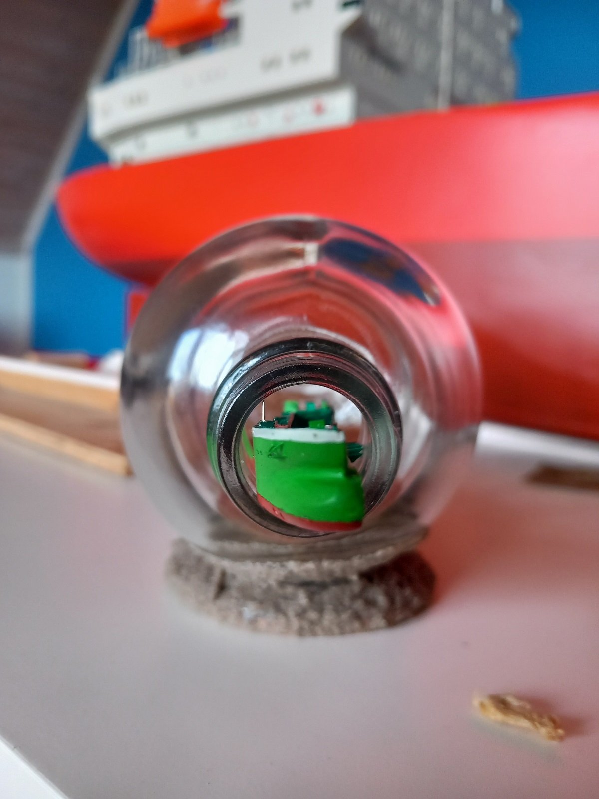
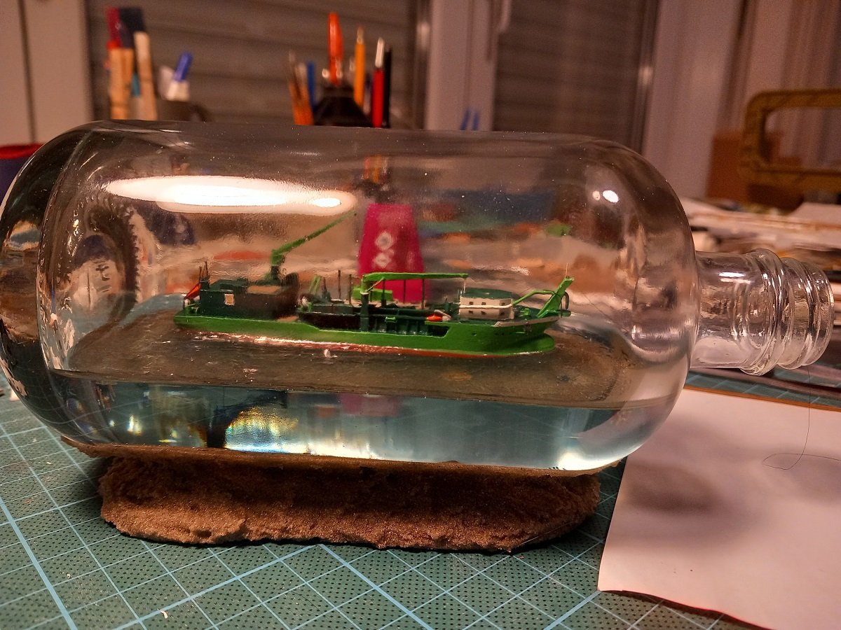
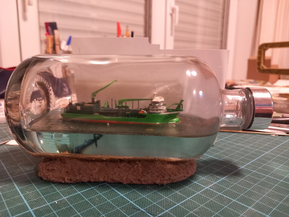
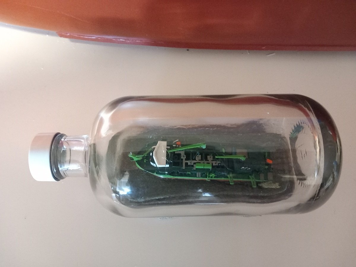
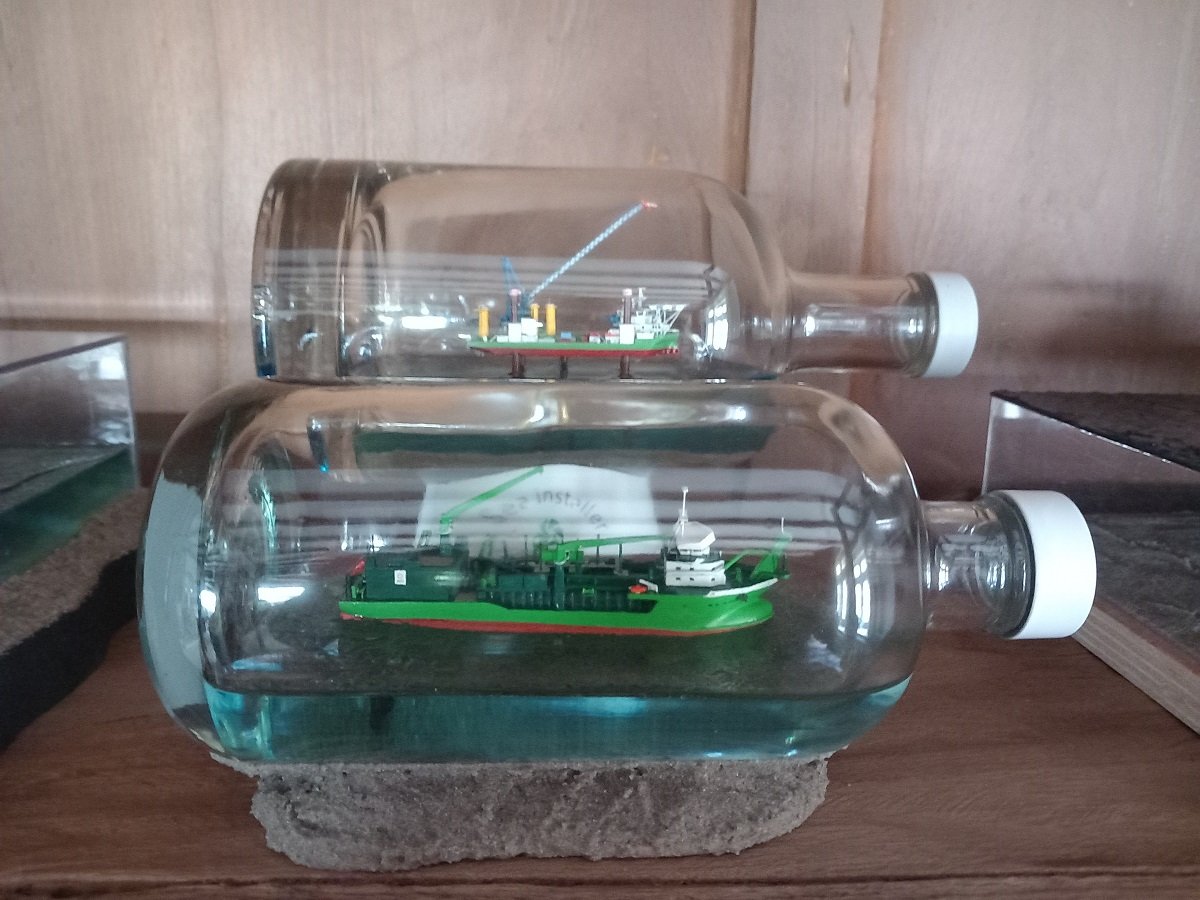
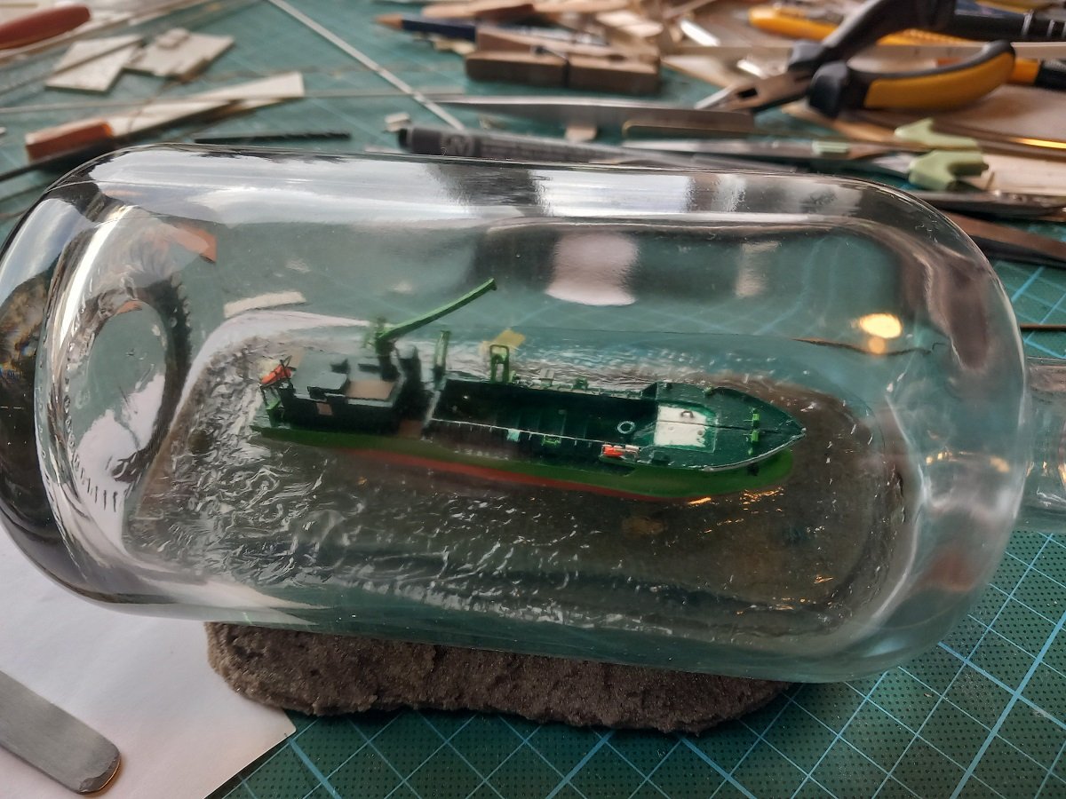
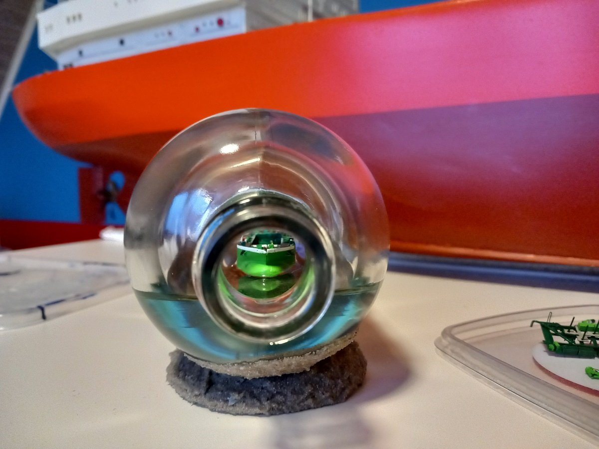
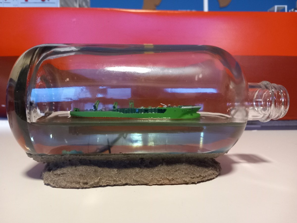
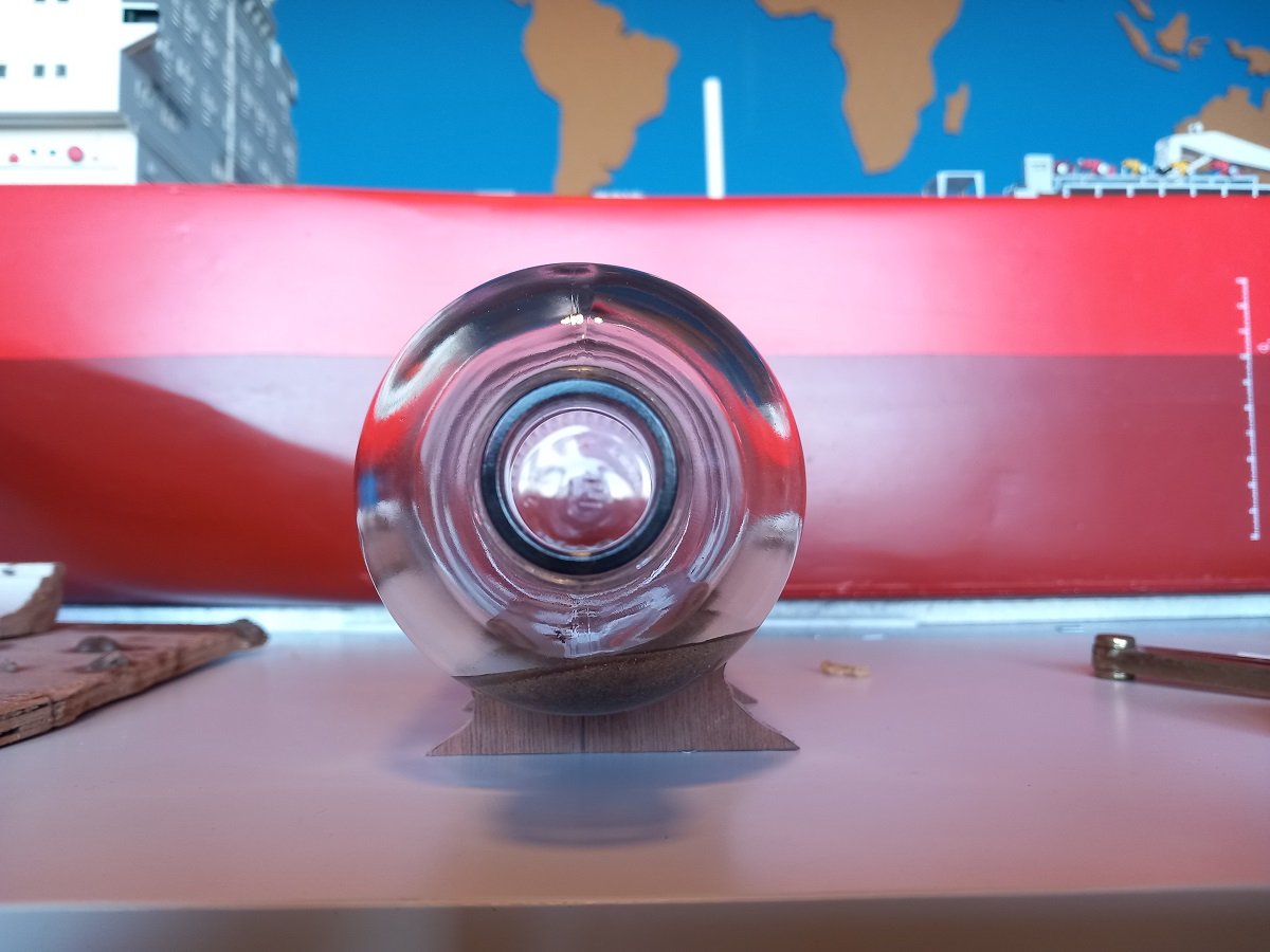
Takes a gas carrier guy to think of such things ;). Changing atmosphere in gas tanks is done in the same way, except that those pipes are fixed of course. @Glen McGuire, I didn't put too much pattern in those waves since I knew it would shrink that much. In this scale, the shrinkage of the gel is actually an advantage. Time to finish this up, there really weren't that many manipulations to do anymore. As mentioned yesterday, shouldn't forget to pass the unicaenis through the bow connection before inserting, otherwise it would get really hard to pass it inside that bottle. There was a slight bend in the main part, with either the accommodation or the aft end wanting to come up. So eventually I glued the forward part first and had to get creative to hold the aft part down while the glue was setting. What are you looking at? Well the aft end of the tweezers is resting on a cup, while the bottle is resting on the center of the tweezers in way of the bottle neck and the open end of the tweezers is pushing down the aft end of the main deck on both sides using the weight of the bottle... I'm not good at holding such a position manually for longer periods of time, I'd probably crush the model or release too early! Hence this idea to let gravity do the work. After some testing when still outside the bottle, I found out that mounting that bridge without knocking the forward crane boom off its support was quite hard. So I decided to glue that boom quite well to its support and I also found out the correct way to mount the bridge to avoid getting stuck on that support. Luckily my ideas worked out the way they were supposed to. And the last action was adding a dab of glue to that bow connection, pulling the unicaenis tights and eventually cutting off the unicaenis inside the bottle. I don't like shiny bottle caps, certainly not with this kind of working vessels (shiny on a vessel like that means it's probably damaged). So I decided to make the cap white. I wanted to put the logo of the vessel on the cap, but apparently that ship doesn't have a particular logo. Here are some pictures taken from below the surface, where you can see that light breaking effect. Together with her predecessor. I don't have time to make a name card etc. I'm currently thinking of making a partially submerged bomb in the sand below the bottle, with the scale and name written on its side. Not too large, not too small. Not entirely sure though. A basic piece of wood seems too easy...

- 70 replies
-
- 10
-
-

-
- Scheldt River
- Dredger
- (and 2 more)
-
Now that's dexterity and patience! Great job so far Phil!
- 288 replies
-
- 6
-
-
-
- Card
- Pre-Dreadnought
- (and 3 more)
-
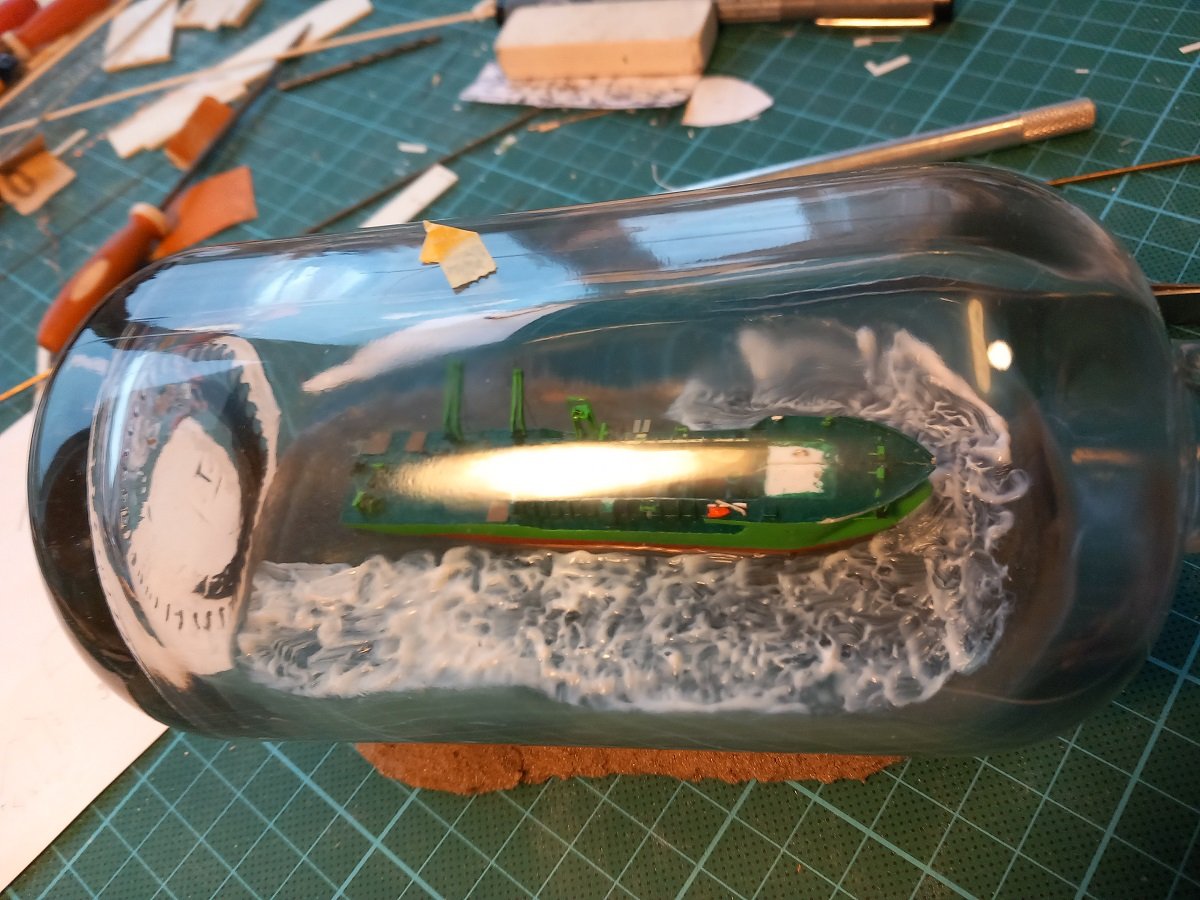
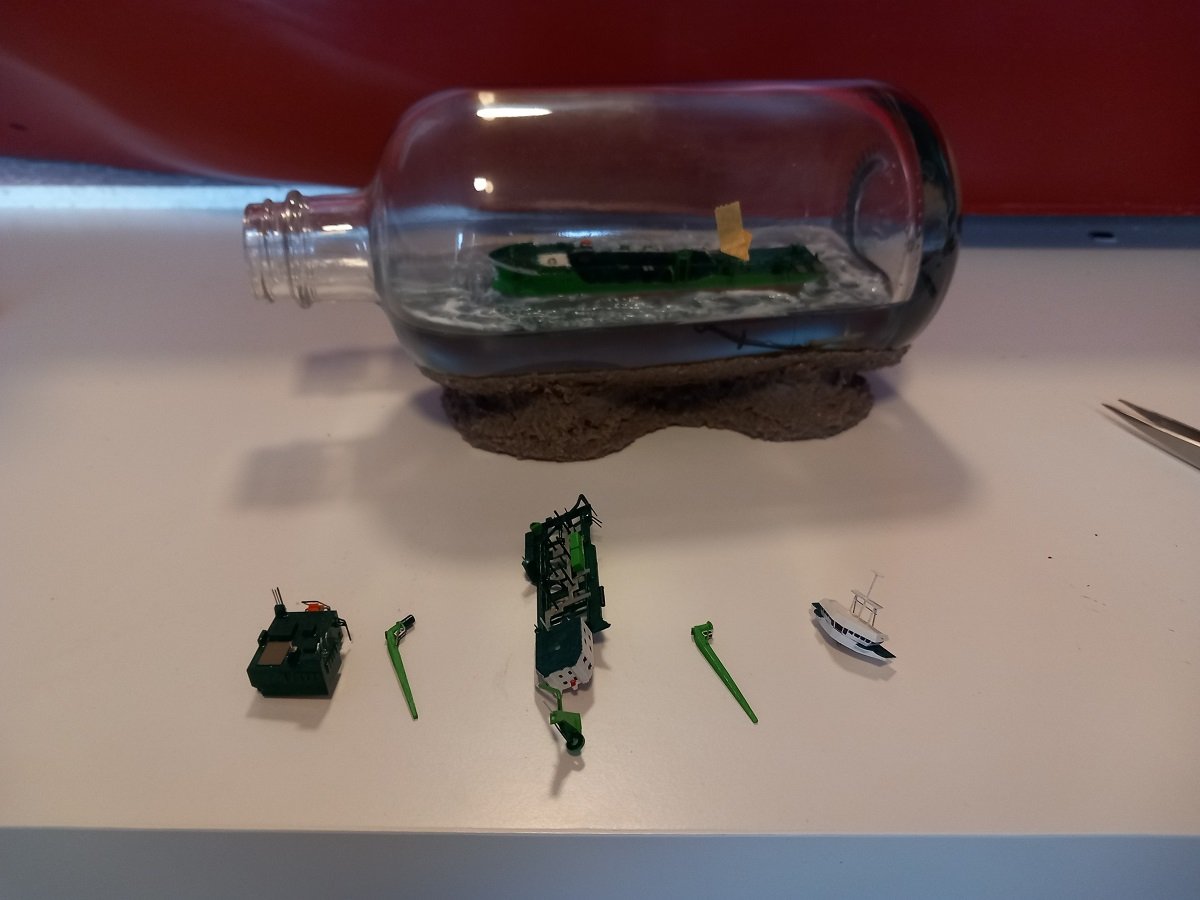
Hi Keith, on the home stretch now. For me the epoxy was something of a critical point. Everything past that should be easier. For this build I planned to make acrylic waves, so that was the next thing to do. The superstructure and rest of the vessel would complicate this if I did it later on. The main hurdle was of course getting around the hull and the pesky unicaenis, which I had to move around to stay out of the way of the paintbrush and other tools used for the acrylic gel application. The easy part first. I did most of this with an angled brush (I saw this trick from @Glen McGuire, but if I remember correctly he actually cut and glued the brush handle). I didn't cut and glue it since I was expecting to change the angle during application to get to all spots. This assumption was correct. Later on, when the angle became too steep, I actually had to cut the hair short to be able to pass the neck without getting all the gel stuck to the bottle neck... Further down the road the brush really became too short, so I took it with my long straight tweezers and used masking tape to keep it in place (you don't want to open the tweezers by accident, crashing the brush onto the ship or in the applied gel). Then came the drying process. I used the same method as I did for drying the acrylic-sand mixture on the Sea Installer build, using a long pipe connected to the air compressor to insert the fresh air in the back of the bottle and let the moist air escape through the neck around the tube. So when it looked hazy like above, I blew air into it untill the bottle was all clear of condensation again. Then I let it rest again and blew again until clear. As promised before, a picture with all blocks in sequence. So construction sequence will be from left to right on below pictures (or from aft to forward on the real ship). Due to the compressor and the thin coat of gel, it only too a few hours to dry the gel. So I started finalizing the ship. And that's where we are with this update. Hopefully complete tomorrow. The most difficult part will be the long part with superstructure in the front, since I don't really have a good hold on that one. I also shouldn't forget to pass the unicaenis through the bow connection before I put that block inside the bottle.
- 70 replies
-
- 4
-
-
-
- Scheldt River
- Dredger
- (and 2 more)
-
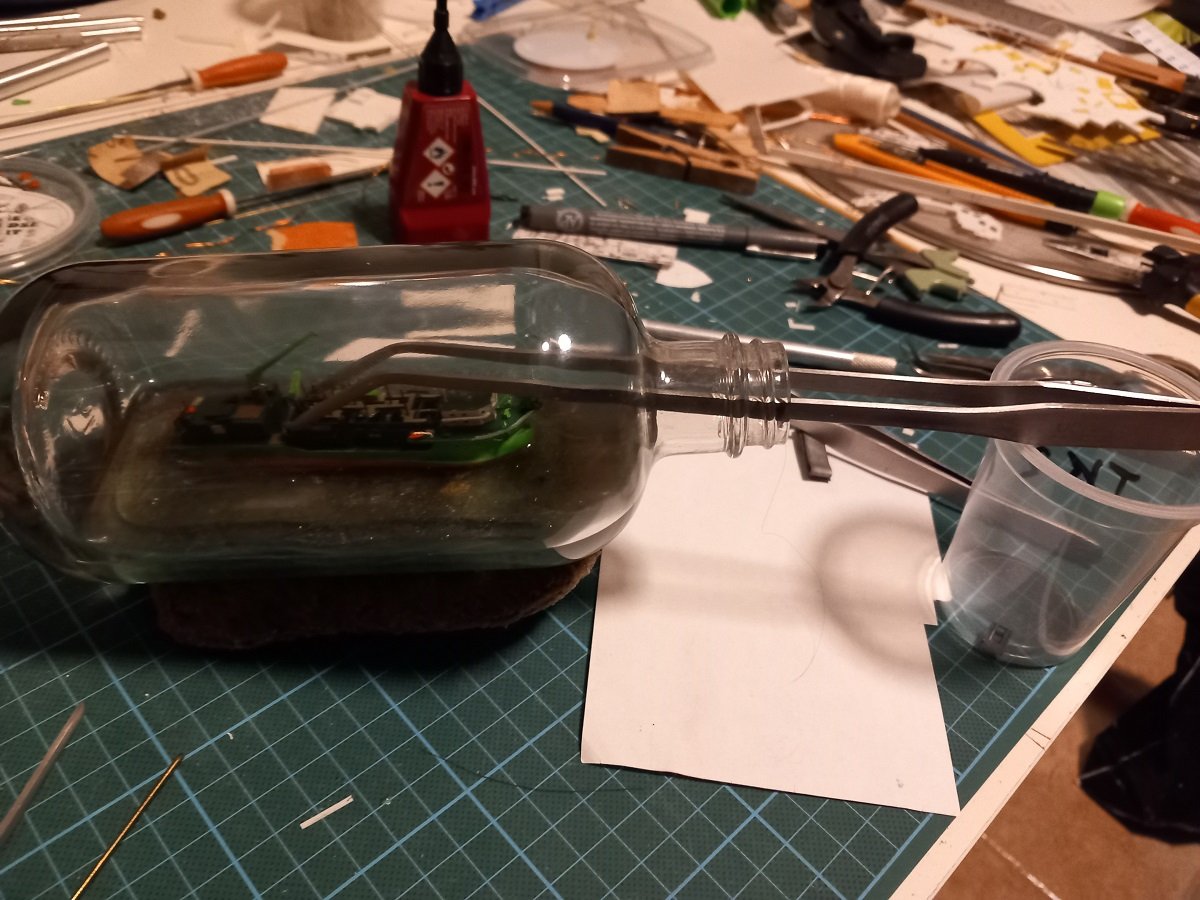
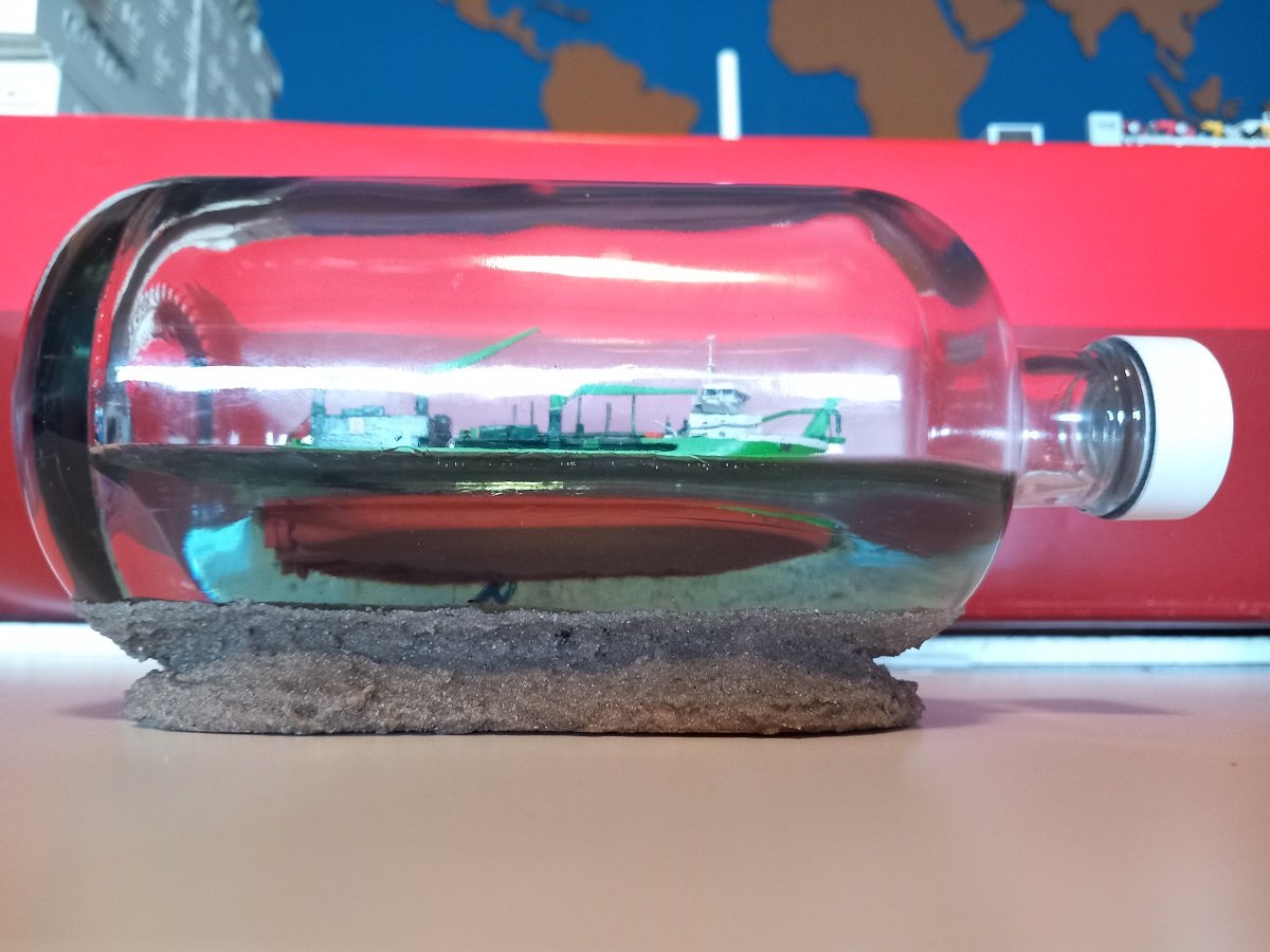
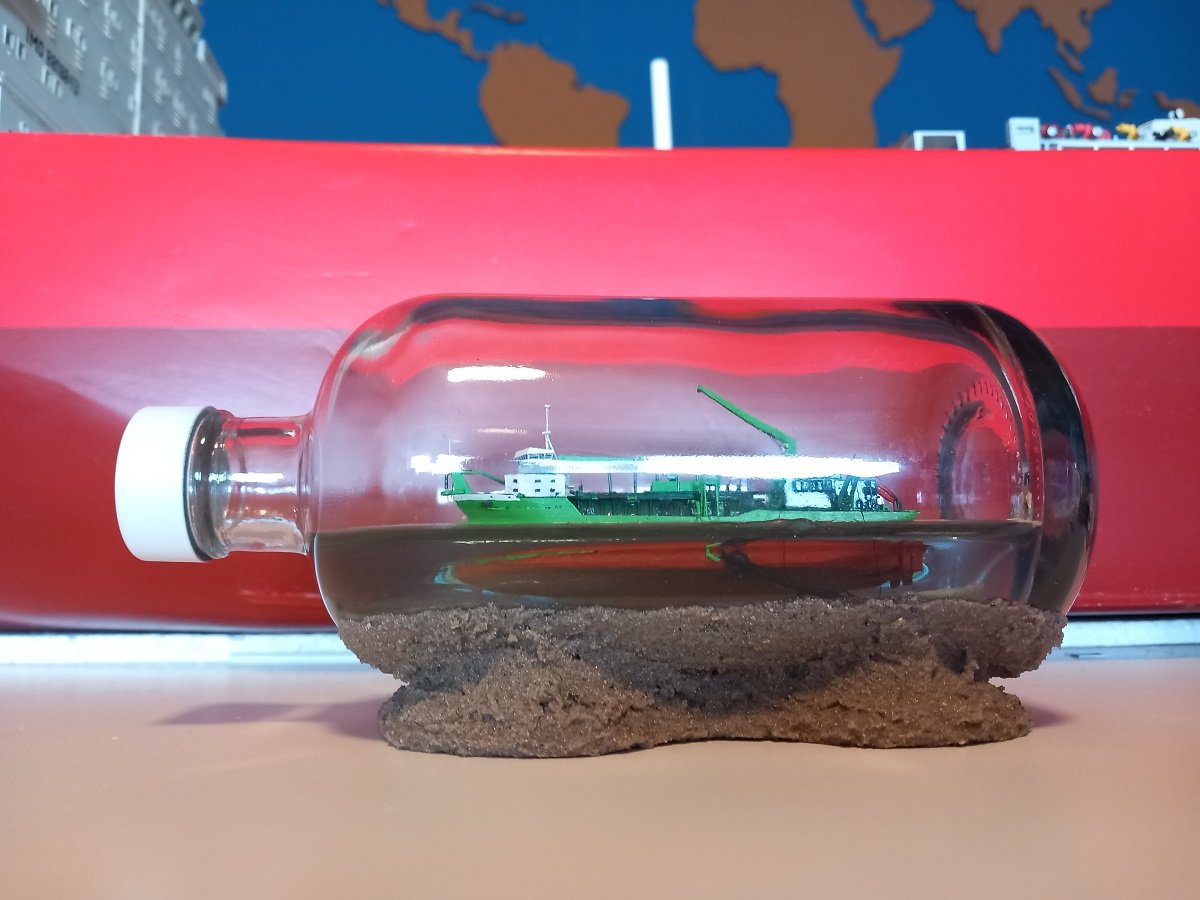
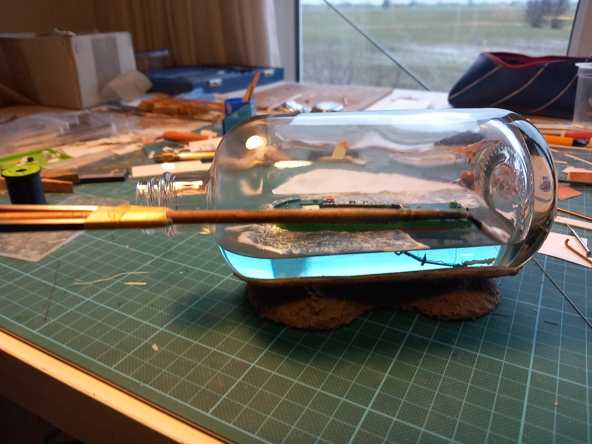
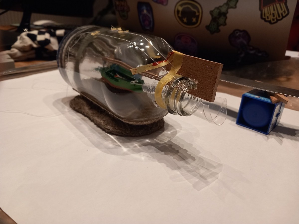
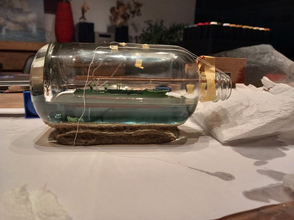
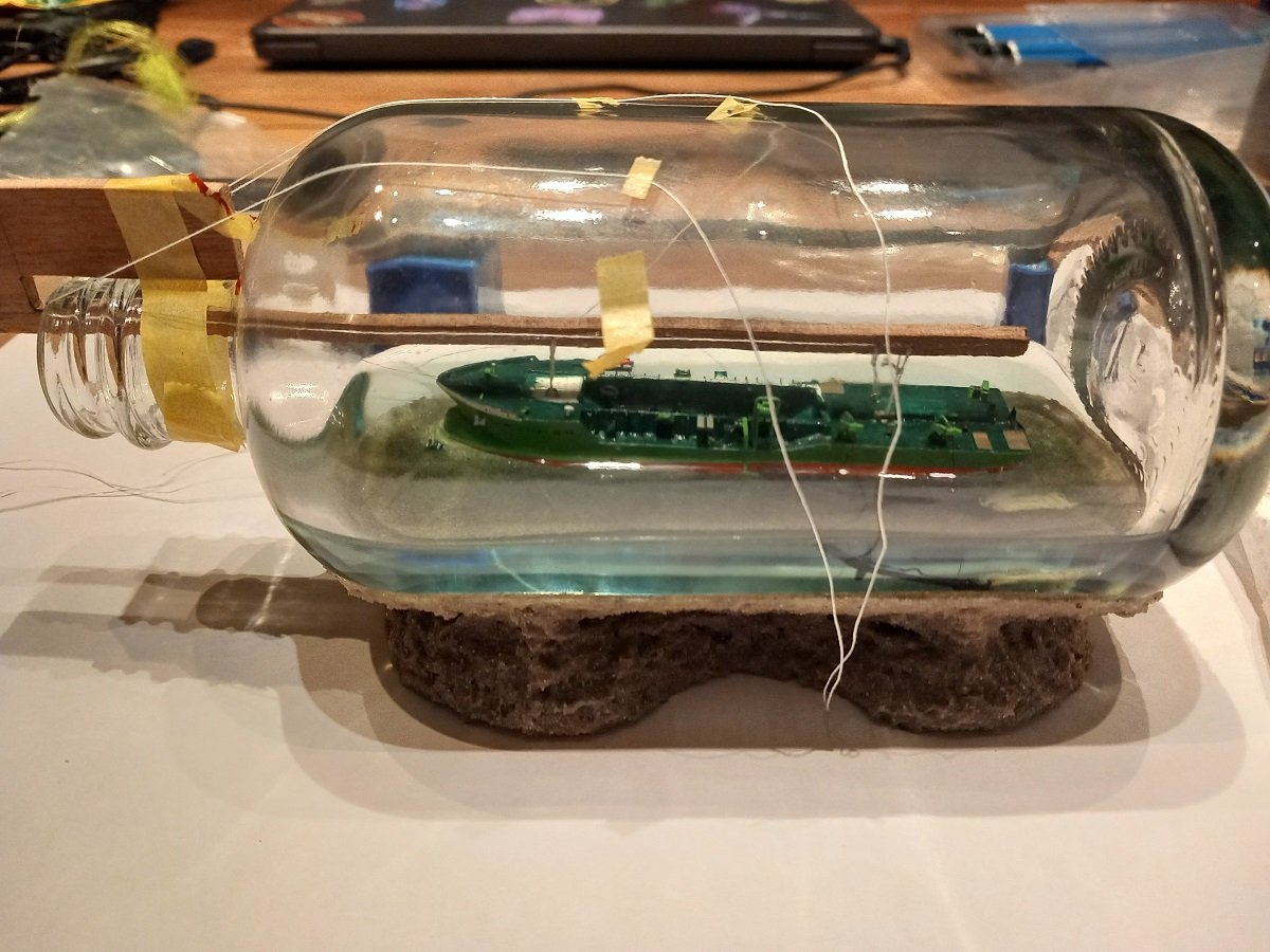
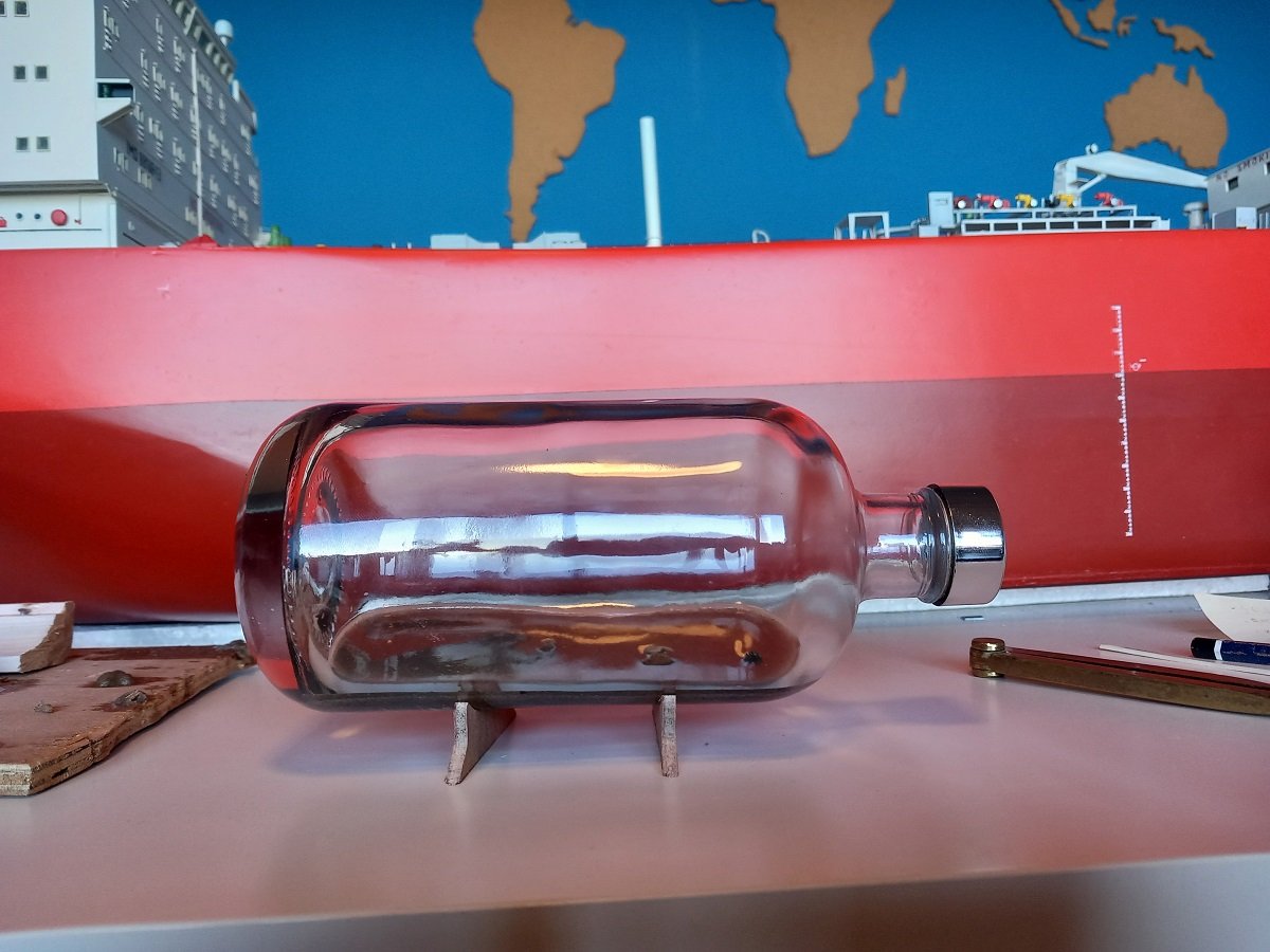
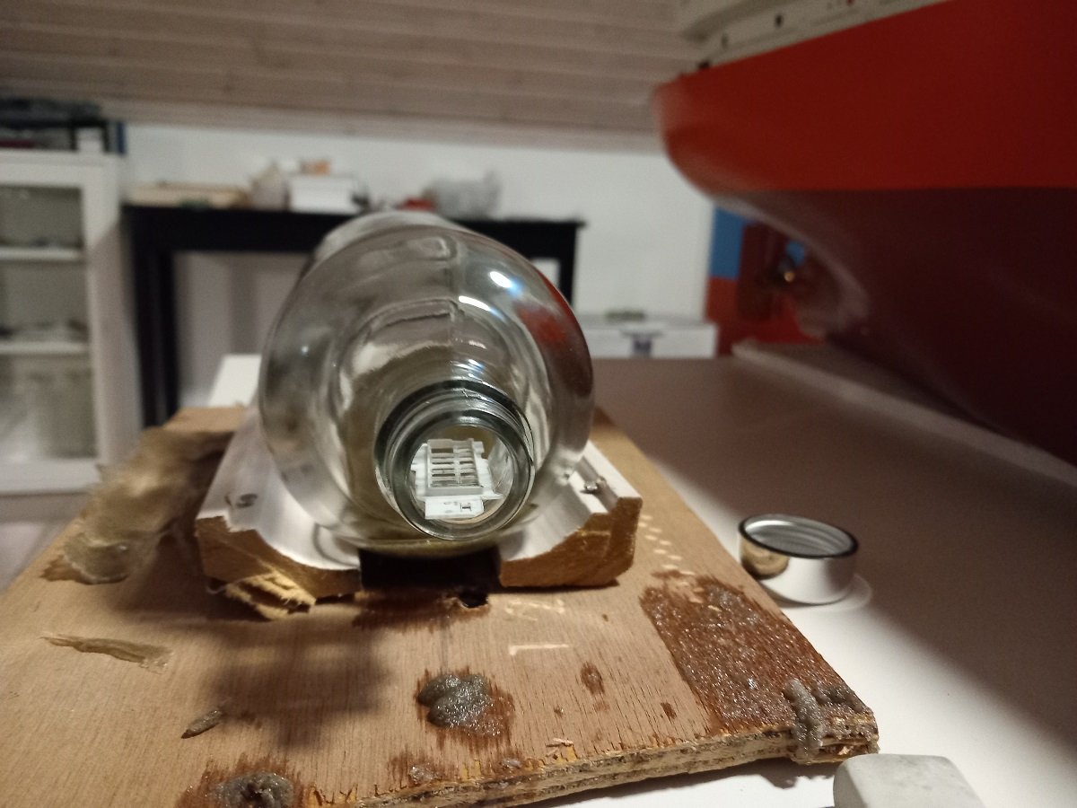
Thanks guys. So on to the pour. No use in leaving it hanging for a long time since I guess the ropes might slip. This has been one of my main concerns for this one. During the pour for the Spartacus build, I added the multicat Auxilia late in the process. When the resin was quite gelly. However the first thing I noticed was that it was sinking, even when the epoxy was already gel. When I pulled it back to the surface (it didn't go too deep), I noticed I really had to pull quite hard to get it out. So I believe it's the "creeping" effect of the gel actually pulling it down rather than simply the difference in densities. That's also the reason I took some strong ropes to hang Scheldt River up in this case. I really didn't want her to be partially sunk. Additionally when I was mixing, I noticed the density of Epoxy is way below that of water. Plastic floats on water, but the epoxy density really is about half that of water, so plastic does sink in epoxy, even without the creep effect sucking it down. For pouring I didn't want to use a hose, since it would be hitting the tool all the time with my clumsiness it would definitely result in the tool rotating and the ship dropping down.... Instead I thought of a slide, which also allowed me to control the outgoing flow better (to avoid the initial splash to end up on deck of the vessel). I used a cut-up cup to insert in the neck. I thought the regular down slide of the neck would be enough to avoid overflow, but it didn't. It was also a bit short, resulting in my pouring some resin on the tool (without consequences). Of course the last bits were tricky, since I really didn't have much allowance between too little or too much. The reflection/light bending gave some difficulty in correctly estimating it too. Looking from the neck would have been easier, but the slide was there of course. I was however well prepared with a big plastic covering the table and some rags stand-by to contain any spillage. In the end, what I learned is to use a longer slide and to give it more down slide and at least close the outside end to have less spill. I only removed the tool when the epoxy was fully cured for fear of seeing the ship being sucked down if it was still somewhat liquid (something I saw on that multicat as well, very late in the curing process). I use the leftovers of the resin to test if it is hardened and only then I try the epoxy in the bottle near the neck. This is to avoid having uncured epoxy on my testing tool, leaving a mark in the end product. What is quite obvious on the above picture is that the bottom disappeared... Somehow the light breaking on the bottle glass and resin, gives a certain light bending effect. Nothing of the sand-mixture bottom is visible unless you look from the top. Additionally when you look from slightly below the epoxy level you don't see the side of the underwater ship, but instead you start seeing the bottom of the vessel. I'll take pictures of that later on. The one remaining piece of masking tape is still holding the UniCaenis rope. The bottle is quite dirty from handling it, so it still needs some cleaning. One additional conclusion is that I didn't get bubbles during the curing process, so it indeed was that acrylic gel-sand mixture that created those.
- 70 replies
-
- 6
-
-
-
- Scheldt River
- Dredger
- (and 2 more)
-
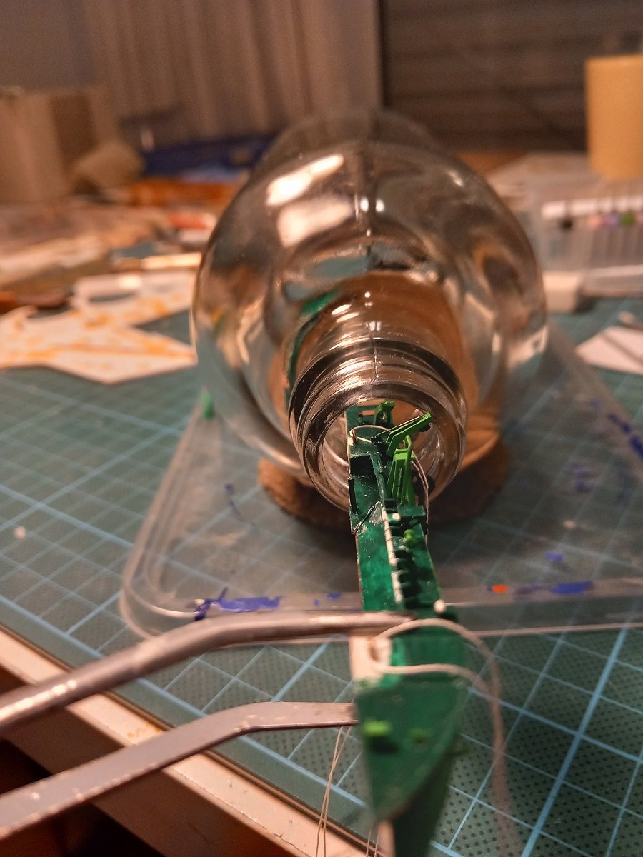
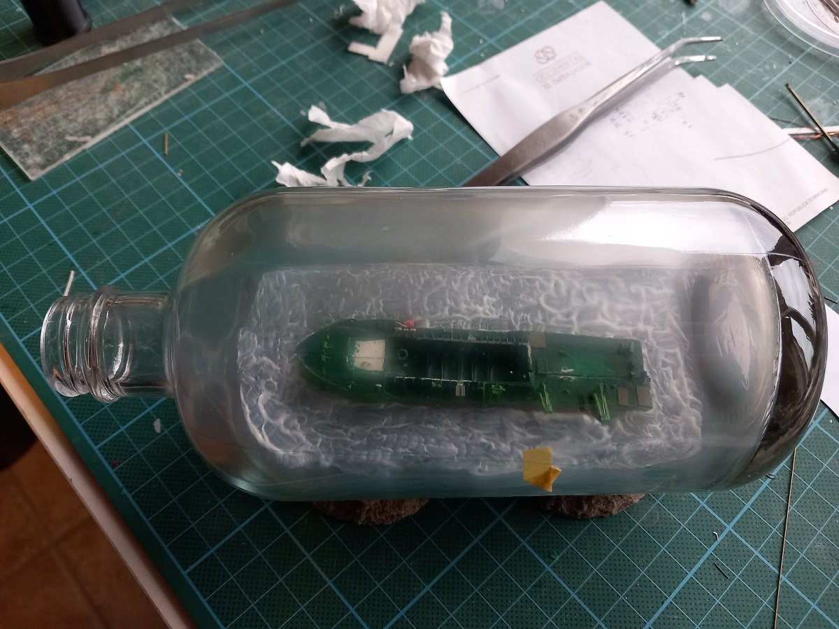
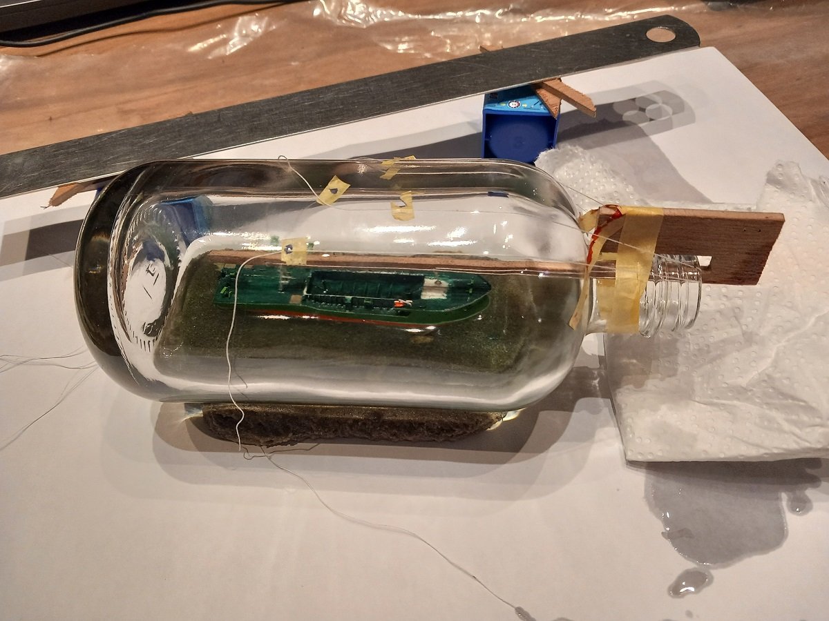
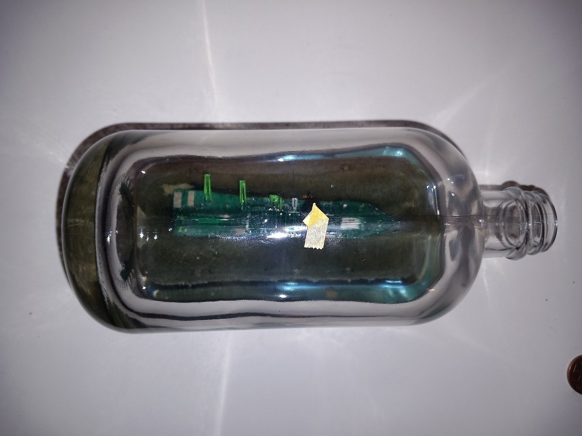
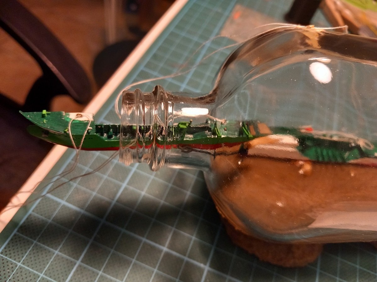
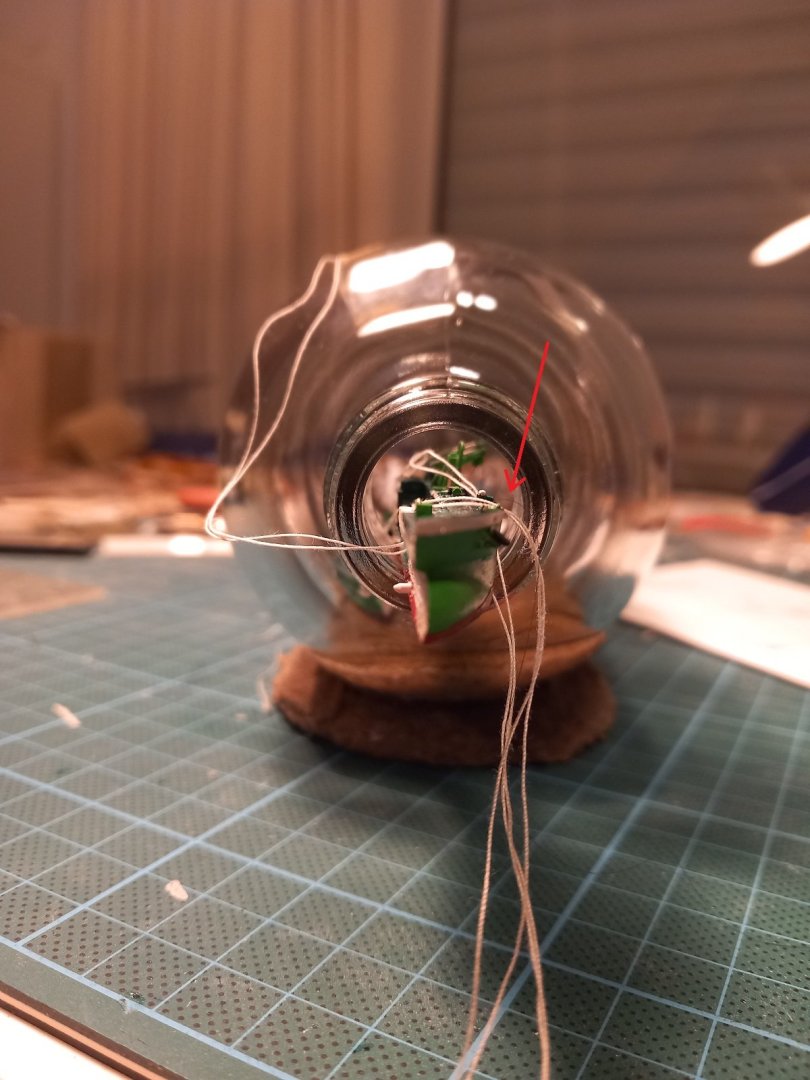
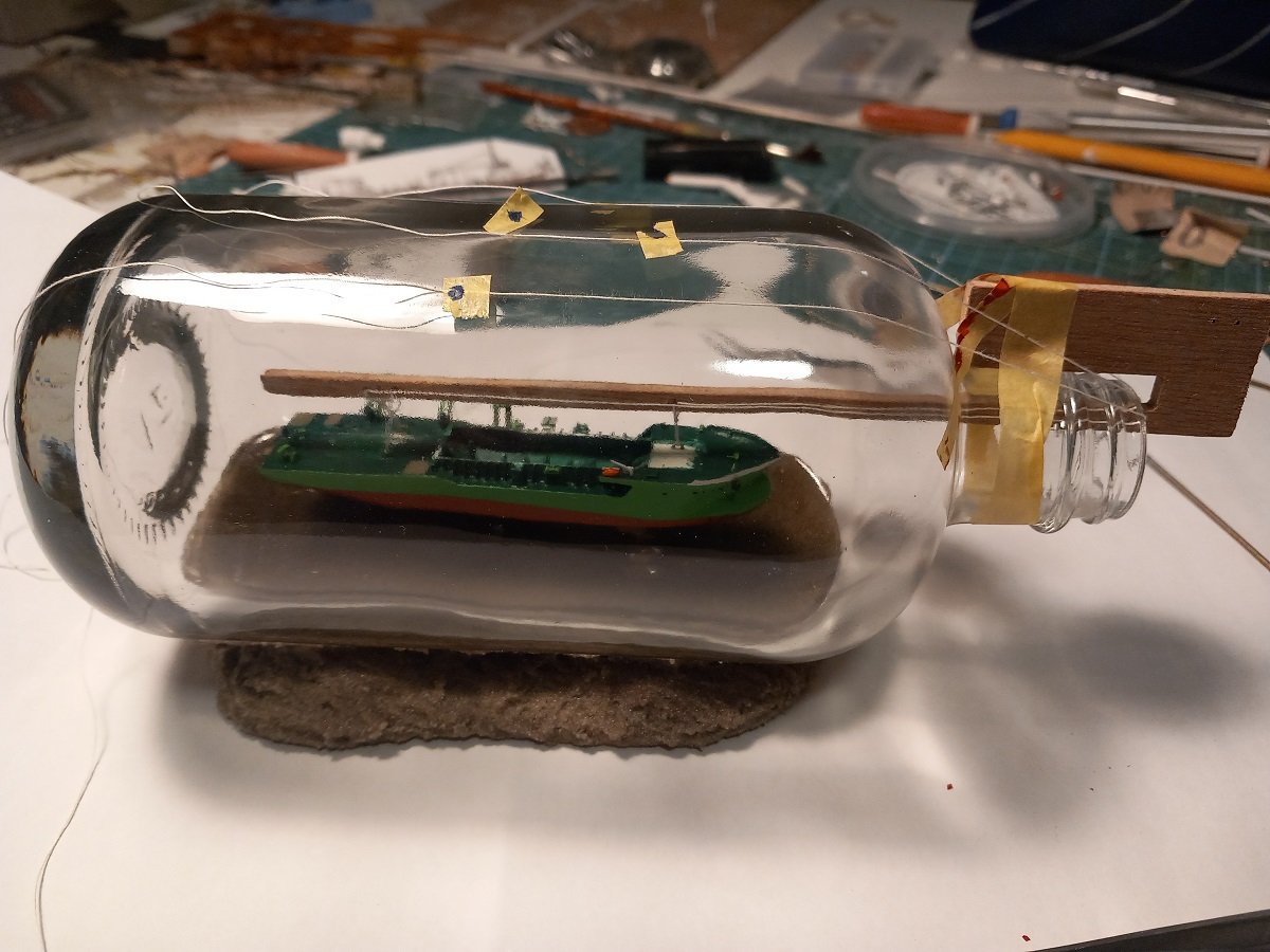
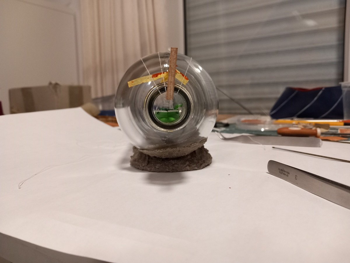
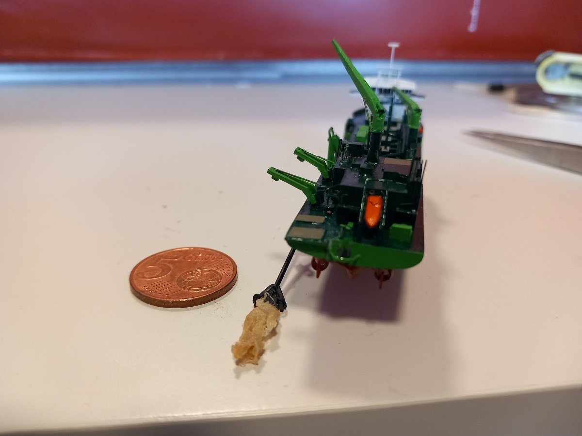
Thanks for the comments and likes. No time to lose, so here is the repair on the aft. Once all parts were repaired and repainted it was time for insertion into the bottle. I decided to deploy/rotate the gantries when the PS half was still in the neck, but the gantries inside the bottle. This way I could hold the hull and still rotate the gantries. I used some slow CA to glue them. Now, of course that malicious Uni Caenis was still there and it's been trying to sabotage me all the way. Here is a picture that shows how thin it really is. The problem was also that the winch is mounted on the vessel, somewhere close to the neck, so even pulling that rope tight isn't an option to really get it out of the way. (it's the black line near the tip of the red arrow). I kept it stuck with some masking tape to the outside of the bottle. Both halves mated inside the bottle and hung up on the tool. Here you can see I started working on a big white sheet of paper to keep better track of the pesky Uni Caenis. And a front view to check the list of the vessel. All in all I spent about 1 hour adjusting the position of the vessel. I wanted to maximize height above the bottom, but also needed to adjust the list and trim each time. The anti-fouling painted under an angle, the way it is, makes it quite difficult to see whether the vessel is evenkeel or how it's trimmed. Eventually I used a 0.5mm brass rod attached to a small water level to have an idea where the hull was sitting compared to the neck and how it was trimmed. Once happy with the position, I stuck each rope to the outside of the bottle with masking tape and made small markings on each rope near the neck to mark its position, just in case the tape would slip. Making knots on the tool and having only 1 line running outside instead of both ends of each rope really was a blessing.
- 70 replies
-
- 11
-
-
-
- Scheldt River
- Dredger
- (and 2 more)
-
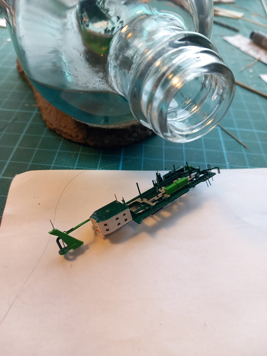
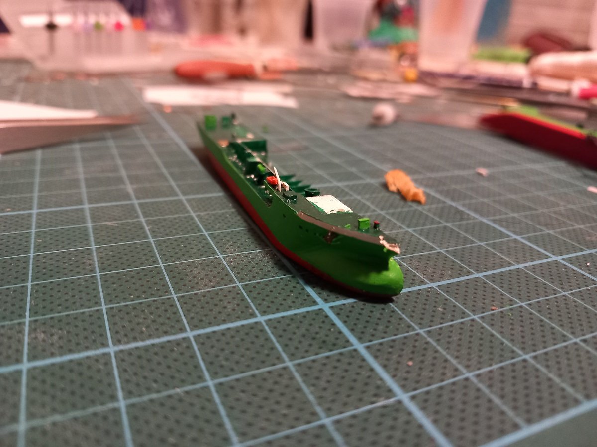
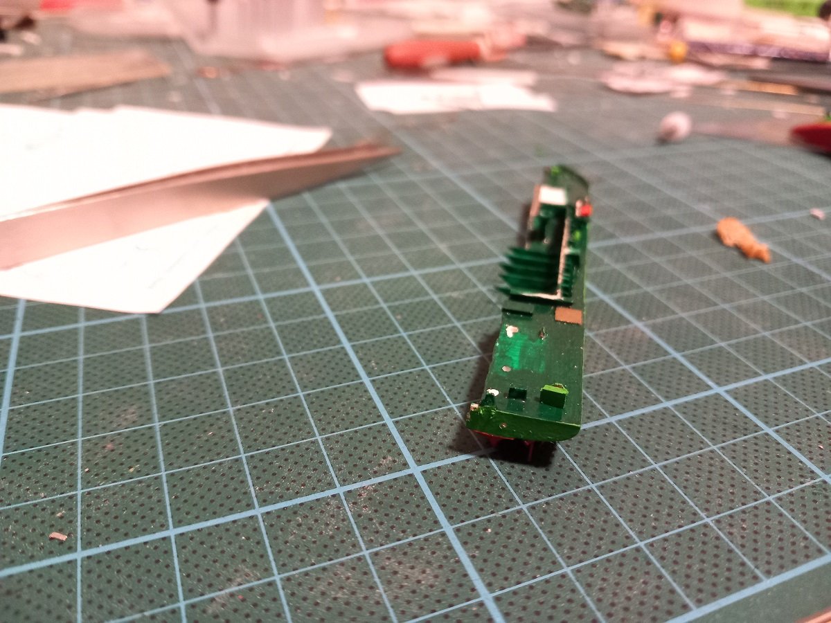
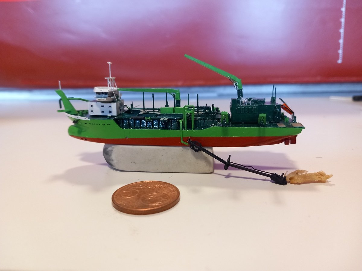
Well, so what happened? In the end there was a tiny issue remaining. There is a winch on PS with a wire that leads up on the bow connection to lift the floating line into the coupling. I wanted that wire to be depicted, but never had a really good idea how to do that, since the bow piece was on a different part of the model. Eventually I figured out a way to do it, but I had to use the hair-thin Uni Caenis thread. So I glued a long piece of uniCaenis to my winch and glued the winch to the model. All said and done the model was resting, with only the two hull parts on top of the eraser with the winch attached. That Uni Caenis is a rather curly kind of thread and (definitely with the dark green back-ground of my cutting board) nearly invisible. I wanted to grab the thread with my tweezer tip, but failed since my tweezer tips don't close properly anymore. However, during that manipulation a curled part of the rope got between the back of my tweezers without me seeing it. I moved back with my arm since I had the idea I didn't grab it and the whole ship came with it. During my surprise jank, the PS part remained attached and dangling on that rope and winch, but the SB released and crashed to the floor. After my initial shock, I saw it laying on its side and thought it was ok, but upon closer inspection it really wasn't ok. Don't know how (or how many times) it hit the floor, but somehow a mooring winch on the aft along with the aft anchor were gone (anchor support still there but thrashed), but worse, the bow section broke off. The bulwark broke where I drilled the 0.5mm fairlead hole, but took some of the filler with it. Also the "cloud" broke off the dredge pipe, but that was really no concern. The dredge pipe gantries also came off, dangling to the ropes on the dredge pipe, but since they were just dry fitted over pins, they released cleanly. On the first search I found the winch back. The anchor was of course nowhere to be found. But both of them were not my concern. That would could not be fixed in any proper way given the size and bulwark breaking. Filing/sanding after applying any filler would definitely ruin that bow and I'm kind of eager to finish this project as it has stalled the Chaconia build for long enough. But here comes some good news. I was kind of "lucky", because I found the broken part back. Tiny as it is, it does seem to have broken in a clean way, so I managed to glue it back on. It only needed some paint. The clean cut on the fairlead was a good match, so it's hardly visible. There is only a tiny corner missing, but that corner is hidden below the bow connection platform, so I can live with that. At first I feared for a total loss as I wouldn't be able to fix that bow in probably a week's time, but now we're back on track.
- 70 replies
-
- 8
-
-
- Scheldt River
- Dredger
- (and 2 more)
-
yeah, so I dropped it... On the floor that is. An update after battle damage assessment will follow soon.
- 70 replies
-
- 9
-

-
- Scheldt River
- Dredger
- (and 2 more)
-
beautiful work on that lantern Olli. Great work on the kit itself, a very handsome hull shape. You've captured it well!
-
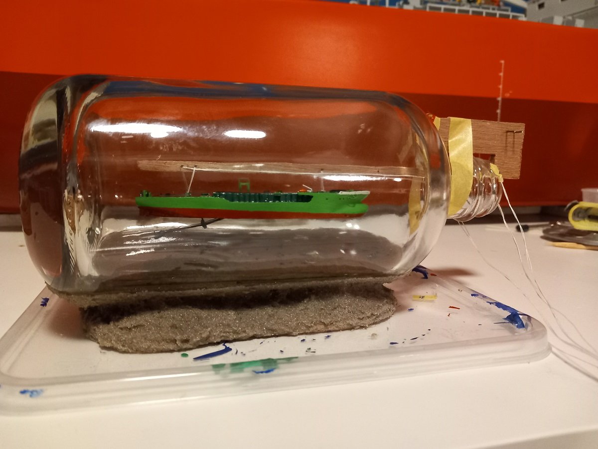
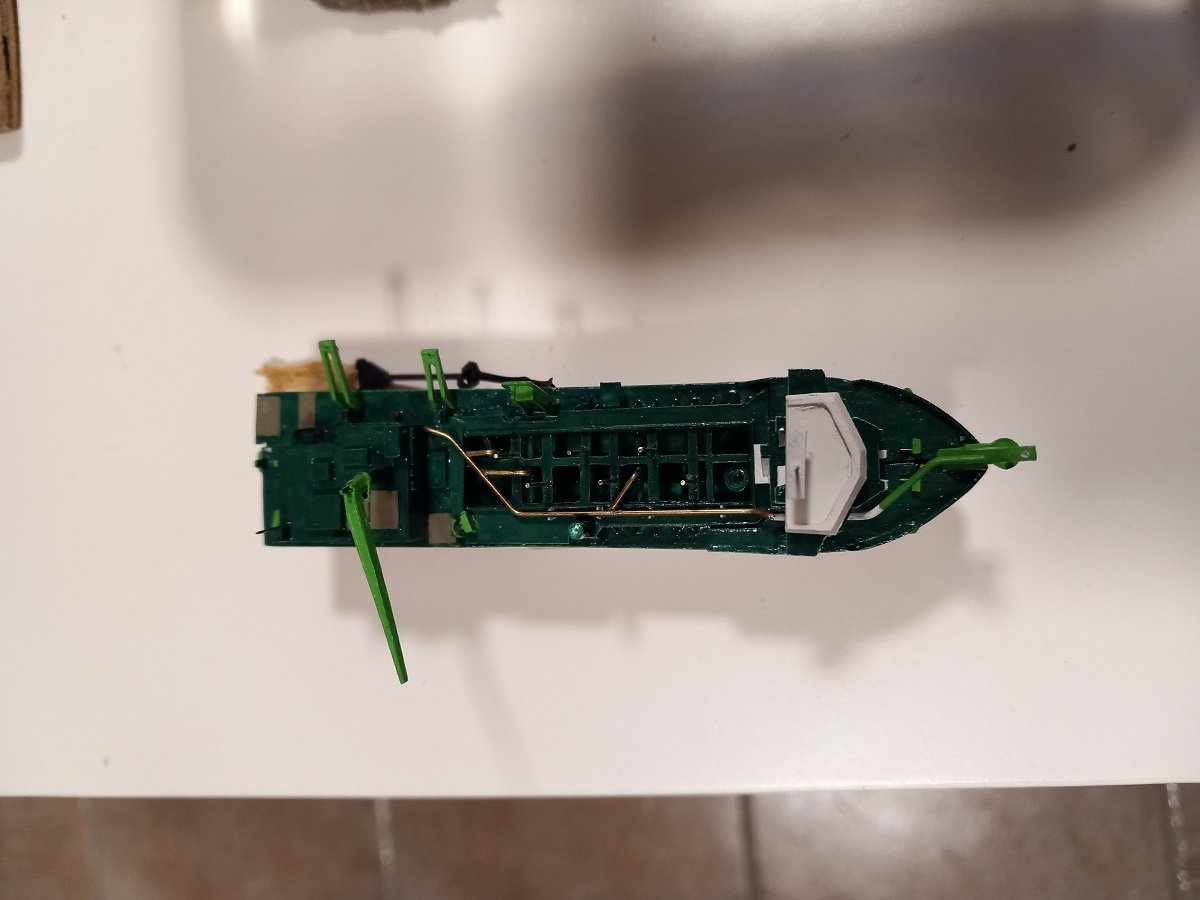
Thanks a lot Gary and Keith. So big update this time. I came to the point where I had to make a test to see for the height/depth of that dredge pipe and position of the ship. First the ship, she wasn't finished yet, but far enough to go for that test: Then the test. SB part went in quite well. The stones I put on some positions on the bottom are a bit annoying and risky for paint damage, but I can live with it. I rotated the bottle so the piece would be on the edge between glass and sand layer. Then PS piece was a bit of a surprise. The aft gantry was rotated and passed well, the forward one, which I didn't deem a problem, appeared to be very much of a problem. In fact as bad as the aft one when I did a dry fit. Filing it off wasn't an option, it would be too much filing, down to the hole where the cable should pass. As you can see, the ropes are attached through the lifting eyes. So I cut off the gantry, quite a risky cut, but it succeeded. I continued my test without the gantries. Once in, I dry fitted both pieces together and passed the ropes through the holes in the tool. I then hoisted the ship up to see where the dredge pipe and the hull were. It seems my measurements and assumed position were quite good, the pipe can be used more or less in its end position down. So I'll slightly lift it with the wires to the gantries to keep some tension on those during the resin pour. I learned a few lessons from this test as well, one was that I had the ropes on the aft crossed. That means that when I tried to slack the aft rope, it was stuck under the other rope and didn't want to slack unless I slacked the other one first. I'll need to cross them differently I guess. You can also see two pieces of brass wire on the tool outside of the bottle. I installed those hoping to use them as bollards to hold the ropes. This was not a good idea, in the end I settled on masking tape to hold the rope ends on the bottle. Since the tool wasn't fixed in position yet, it first tried to rotate upside down. I used some tape to hold it in place. It did "twist" a bit in the bottle, but I decided I kind of like the ship to be slightly angled compared to the centerline of the bottle. After learning those lessons I separated the halves again and used the ropes to retrieve the pieces from the bottle. I then finished the ship, only things remaining are some "wires" between the bow connection and a winch on PS and between the gantries and the dredge pipe. Once those are done, I will insert both halves inside the bottle and connect them. The epoxy hasn't arrived yet, so it might be a while before I can continue. The bottom is rather dark, so I'll be using a light blue color for the epoxy.


- 70 replies
-
- 10
-
-
-
- Scheldt River
- Dredger
- (and 2 more)
-
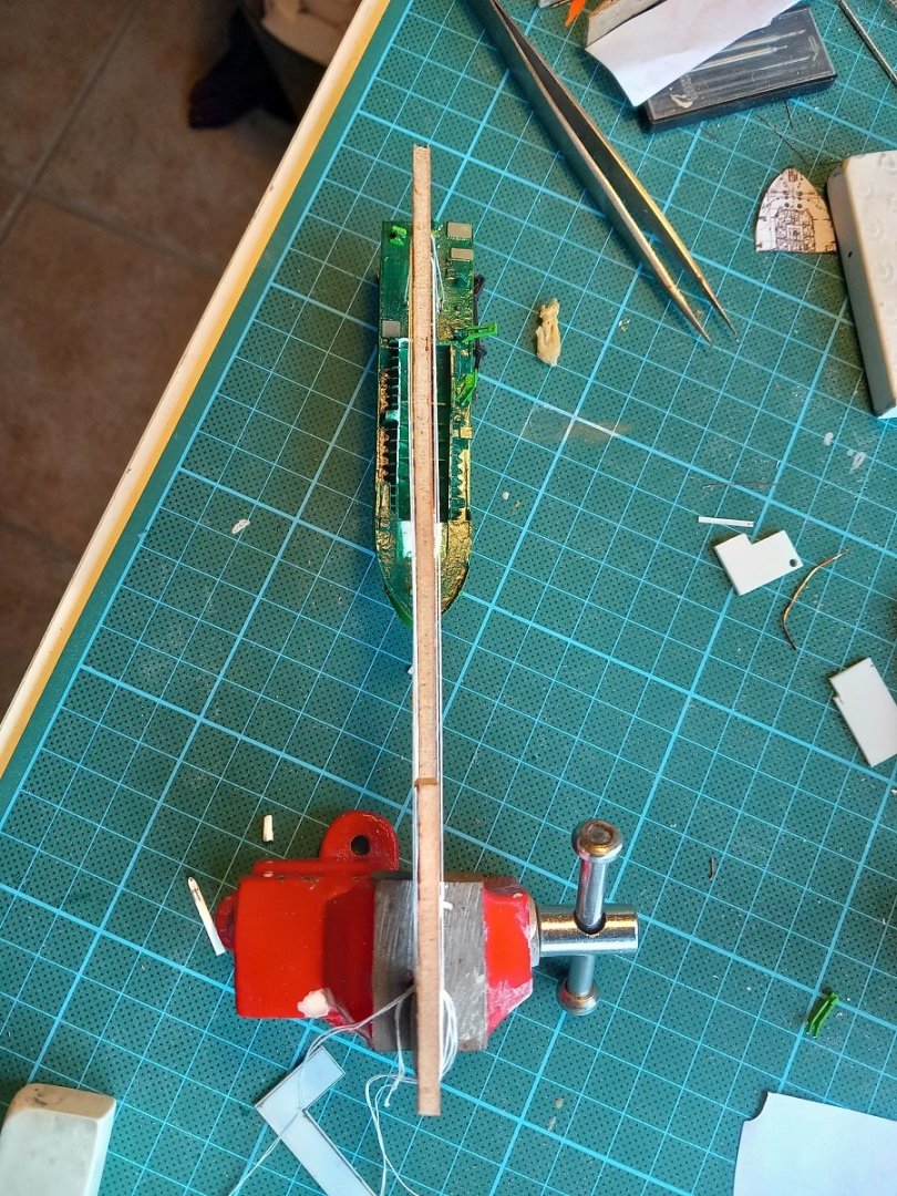
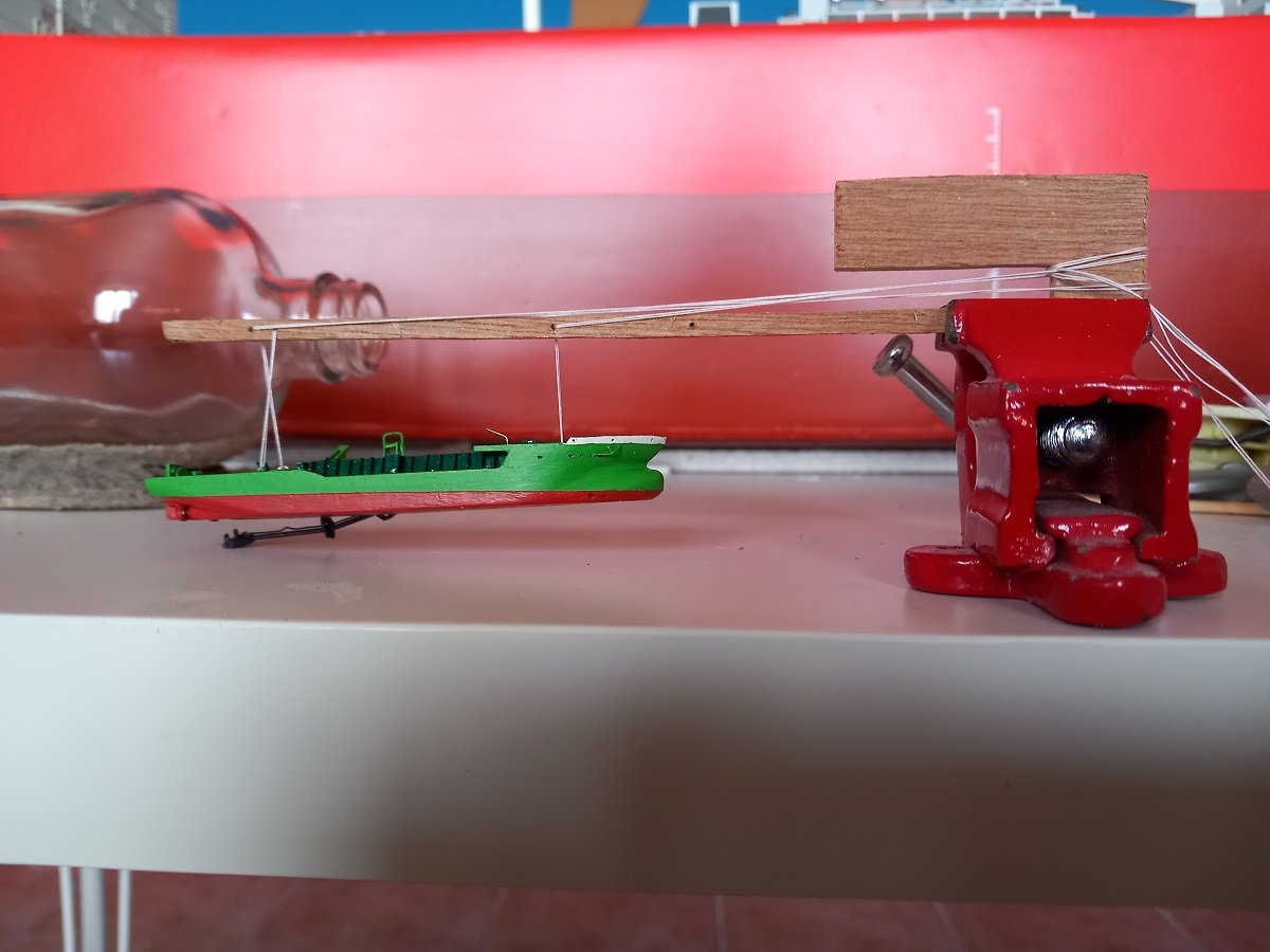
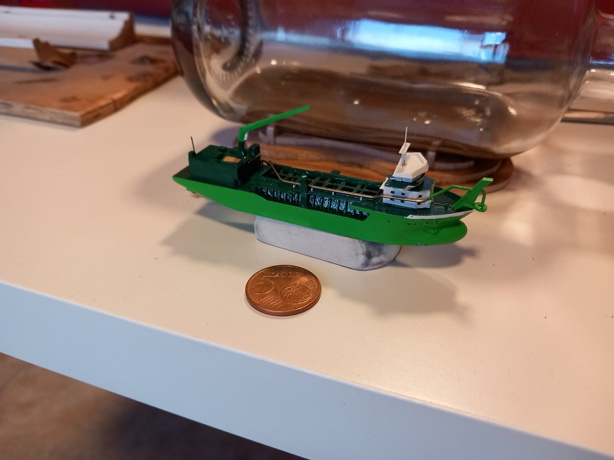
Made some serious progress, eventhough I wasn't expecting to finish it by my next departure. Somewhere I do see a light at the end of the tunnel. So now it's time to detail and to start test fitting to see if all that detailing will even fit through the neck. On the top left of this picture you see a small "measuring stick" on the hull. This one has the height of the rescue boat davit. Luckily it fits, so I can build and attach that davit on the hull. Then it was time for the "tool" and suspension test. It only existed in my imagination and I've thought of several iterations to improve it, but so far it seems ok the way it is. I thought I wouldn't have enough moment to actually tilt it to an upright position, but it works quite fine to adapt the trim and list of the vessel. In the bottle it will be hanging a lot closer to the tool, so I'll do that as well to avoid any surprises. It's quite a tight squeeze in the bottle. The idea is to insert both halves with the ropes through the eyes, but ropes fixed outside of the bottle. Then connect the hull halves together. Then attach one end of each rope to the tool by a knot and get the other end through the hole in the tool and going out the bottle. This gives me 3 ropes out of the bottle to work with. I tried with both ends loose, but that makes 6 ropes and it makes a mess. Further tests will follow during the detailing process. As there really is no room for error once it's in the bottle.

- 70 replies
-
- 8
-
-
-
- Scheldt River
- Dredger
- (and 2 more)
-
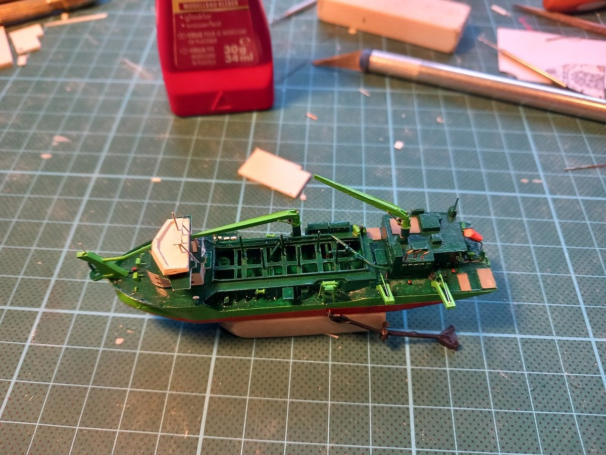
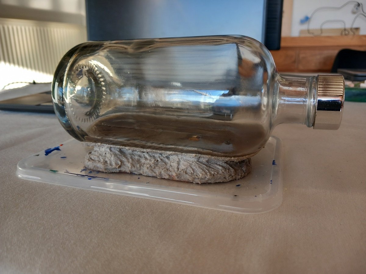
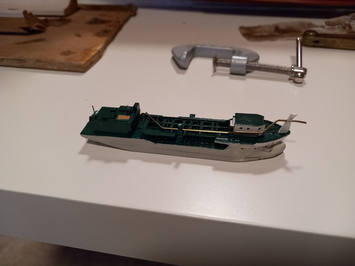
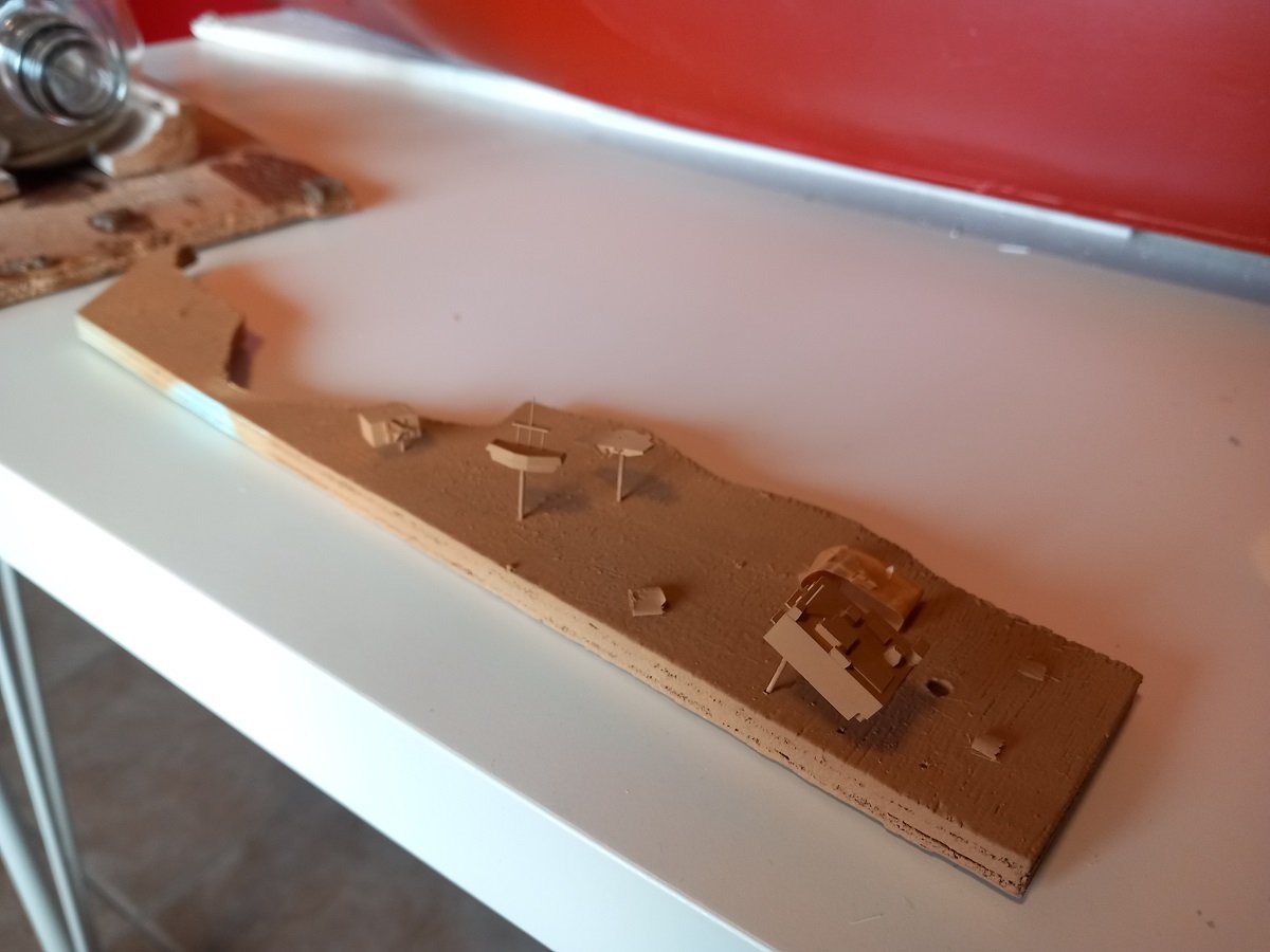
Hi Glen, thanks, but nothing of those steps will remain in the end... The sand will cover all. I have now glued the bottle to the base and applied the first coat of acrylic-sand mixture. The advantage of this mixture is that it sticks well and can be shaped. When mixed with epoxy, the sand flows much more and can't be shaped into hills etc. This was a couple of days ago, now it has dried and the sand has darkened a lot. I'll be adding another layer of this mixture to blend things in a bit more. It's now a very stable set-up. I've "glued" the bottle itself to the wooden stands using pure acrylic gel as well. It won't be rotating on the stand. I've made some serious advances on the ship as well. The discharge line on deck has now been finished. Not sure if I'll put the dredge valves on it. I do have a prototype, so I'll see. I've also mounted the hydraulic cylinders that open and close the bottom doors and the small wooden decks are also painted brown now. That gantry on PS, yellow-green thing, is way too angled, so I'll tear it off and try to get it straightened. Biggest items remaining now are the lifeboat and rescue boat and the catwalk over the hopper (including 2 yellow-green containers. It also needs life rafts The second crane is ready, but can't be easily dry fitted, so it's not visible in the above pics. It needs a support near the bridge, but I still need to see if I mount it on the crane jib (not preferred, will be more difficult to mount the crane inside the bottle that way) or on the accommodation block, depends on whether it will pass the bottle neck when mounted on the accommodation block.
- 70 replies
-
- 8
-
-
- Scheldt River
- Dredger
- (and 2 more)
-
Yes, the reason is simply power. Capstans have more space to allow more people to push, certainly a double capstan. A windlass is restricted by its horizontal positioning. So if you need to pull more weight and have more space, a capstan is your choice. Smaller vessels have lighter weights to lift and are often limited in deck space, so windlasses come in handy. As Phil mentioned, for even smaller vessels it could be done by tackles. I suppose some of it is simply related to time frame, some of it by the accepted limits of human power.
-
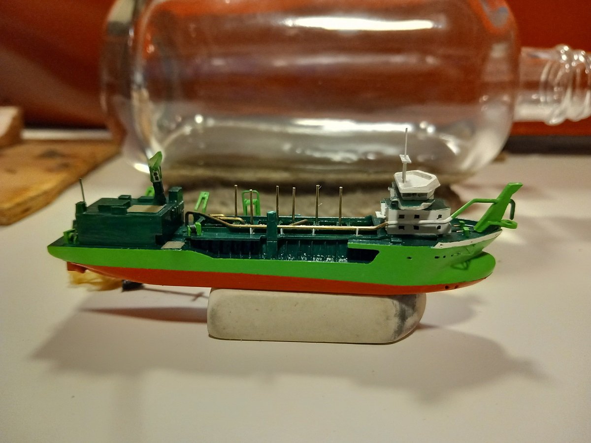
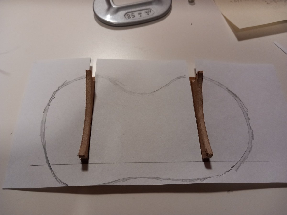
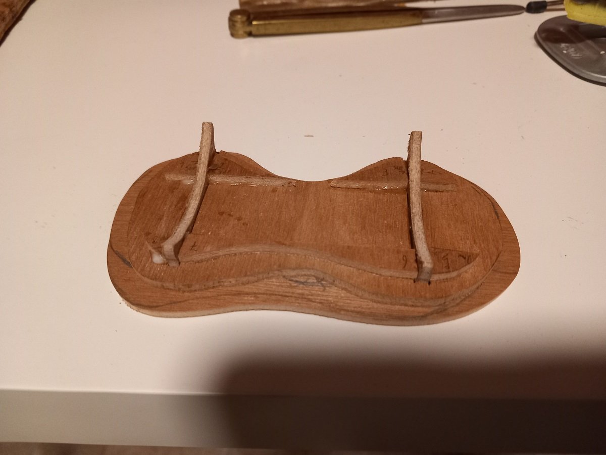
I eventually opted to lower the base and mount the brackets on a base plate with a random rounded shape. I then built up several layers of 3mm ply to cover most of the gap between the base plate and bottle in a stepped fashion. After mounting the base plate, I made a paper template, outlined the bottom layer by striking a pencil point around the contour. I then drew in the next layer, cut and transferred the outline to wood. The next layer I did in the same way. All is glued with PVA now, so I can start applying sand to the bottle. With @Glen McGuire doing his nameplate, I figured out I completely forgot about that with this low set-up. I'll need to fix that somehow. First thought is to make some kind of debris sticking out of the sandy base with the details on them, slightly to the right of the whole thing in order not to disturb the view on the dredger. In the meanwhile I also mixed new yellow-green and painted all ready parts in that color. She's starts to look like a DEME dredger now. The discharge pipe on deck is also in progress and caused some headache (of course!) Bending the pipe itself wasn't such an issue, it was mostly that styrene piece at the bow that was the issue. The one I built when I was onboard was too short and the angle of the drilled hole for the pipe was not good. In the end I rebuilt that piece 4 times before I was happy with it. More parts are ready, but this is more or less where I ended up this morning. Most of it is still dry fitted of course. Finishing the bridge windows now so I can glue those parts together as well. I will still add some detail to the masts later on.
- 70 replies
-
- 9
-
-
-
- Scheldt River
- Dredger
- (and 2 more)
-
Apart from the excellent build itself, the display is very nicely balanced and puts the ships nicely on center stage. Congratulations on a perfect build. I vote for a complete battle of Trafalgar in a bottle for the next build. Admit it, the only way you're going to top this is by having at least 4 ships fighting in a bottle!
- 185 replies
-
- 11
-
-

-
- Flying Dutchman
- Black pearl
- (and 2 more)
-
I'm following for a while and marvel at your tiny detail work, yet in all my excitement I forget to react!! Great job Keith, certainly at that scale it's not easy to achieve what you intend to! Love that tiny boiler and the overall crisp finish of your model.
- 732 replies
-
- 5
-
-
-
- Lula
- sternwheeler
- (and 1 more)
-
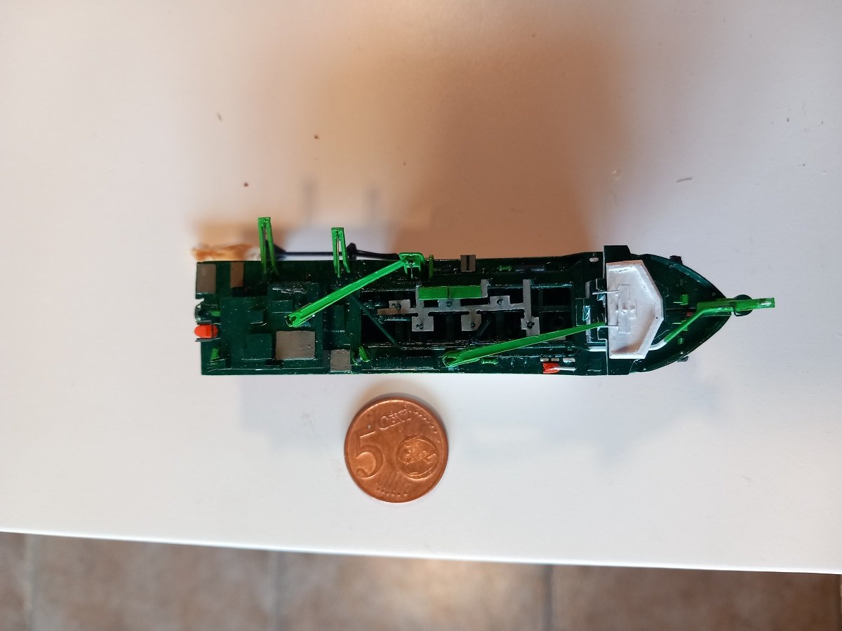
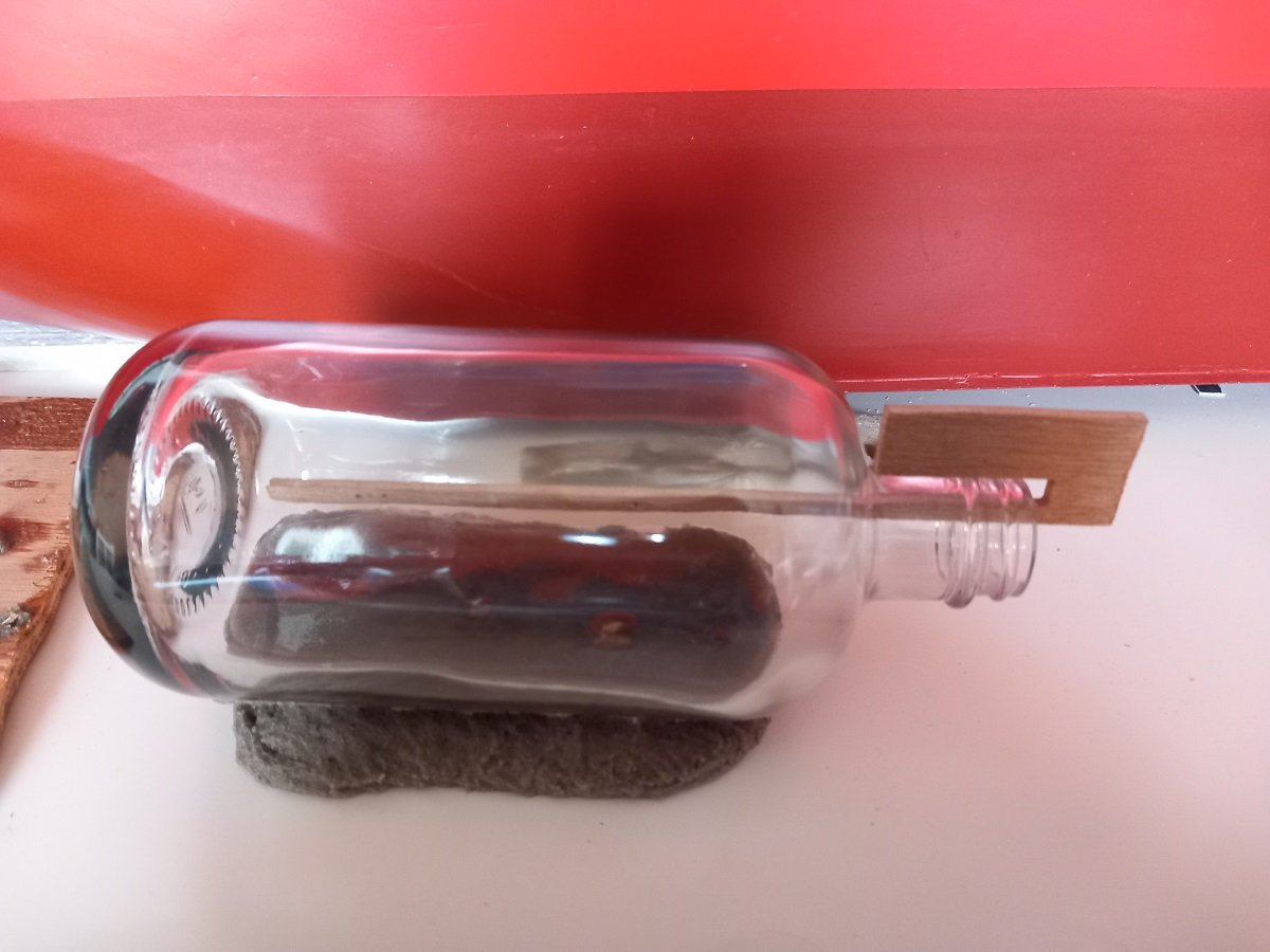
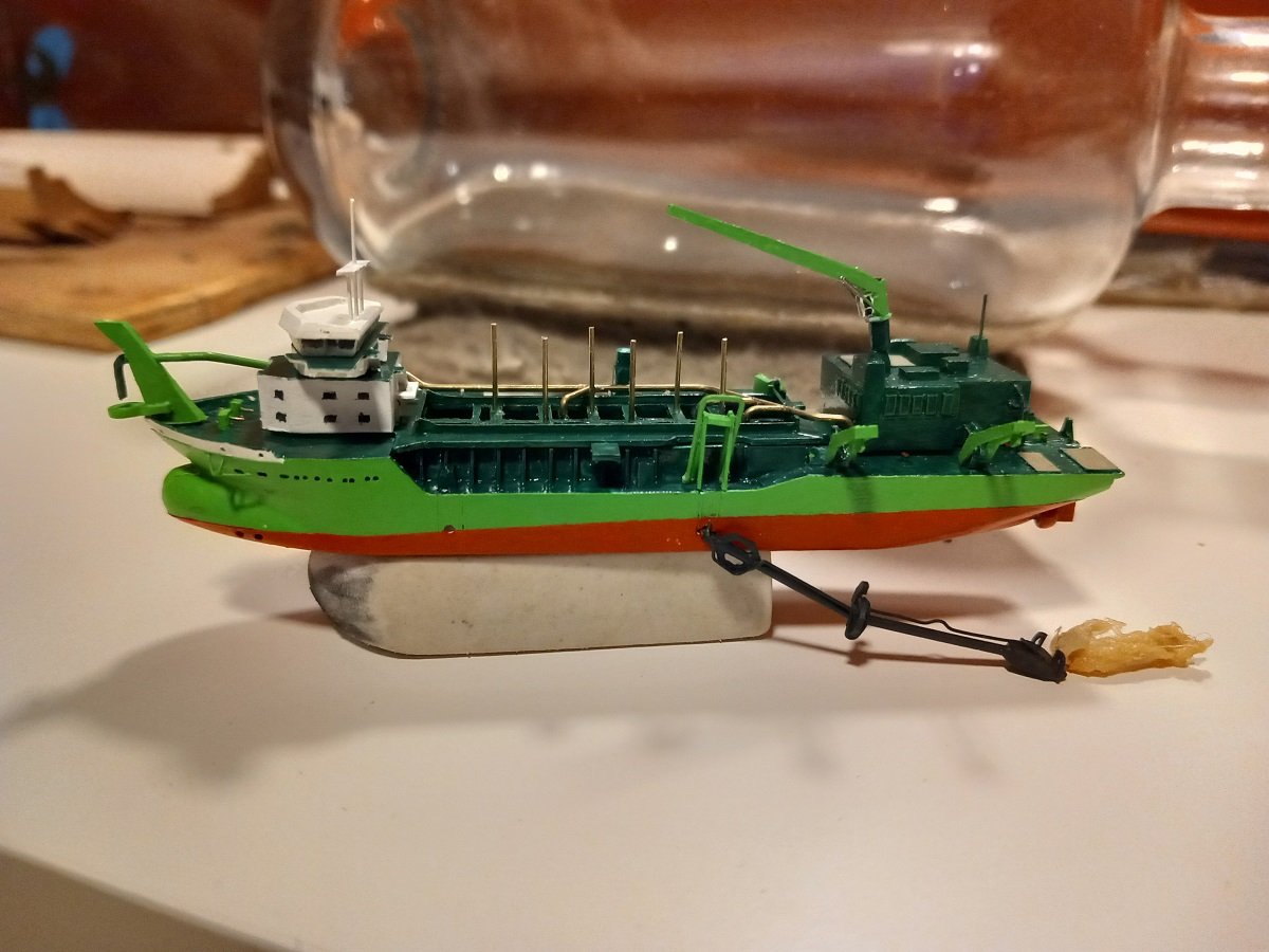
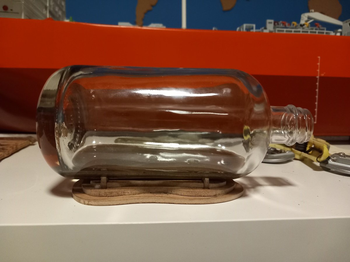
Thanks Keith, All in all I didn't have to invent too many ways to handle or assemble things up till now. I'm now completing all items that need to be painted yellow-green. The other parts are all nearly finished in paint. I will still try to add some red touches to add some color (and because they are truly there on the real ship). After measuring and building of those last details, I decided it was time to connect the dredge pipe to the PS hull part. Still need to adjust the height of that piece, but it's the original piece that was removed in the first place. This means the sides of the hole where the dredge pipe protrudes are matching for a good closing of that hull. You can also see the bulwark is already painted white and you can also see the rudder and anchor supporting structure. The pipe will be in the way for painting that hull, but it had to be mounted to paint that hull properly. In the meanwhile I'm also busy with the supporting of the bottle itself. I'm not planning on turning that bottle around too much when the vessel is inside, so I better fix that sand on the outside of the bottle first. I don't want to rely solely on that acrylic gel-sand mixture to hold the bottle, so I decided to make some wooden supports first. I'll add a longitudinal beam between the two as well. I'll glue them to the bottle with acrylic gel and cover them in sand later on. Not sure if I'll go for a central support only, or if I make those supports lower and then spread the sand in a wider base... And here you can see the bottle neck and tilted sand bed.
- 70 replies
-
- 9
-
-
- Scheldt River
- Dredger
- (and 2 more)
-
I think it was a good call to change the base. The big piece of wood probably would have taken too much attention and make the bottle disappear. The new base looks awesome and will make people focus on the ships (and whirlpool!)
- 185 replies
-
- 6
-
-
-
- Flying Dutchman
- Black pearl
- (and 2 more)
-
Great build so far. However I was wondering about the aft part/stern. The balsa? fillers make sense, but how is this faired with the hull planking? Love that wood tone on the outer layer. A pitty to paint it.
-
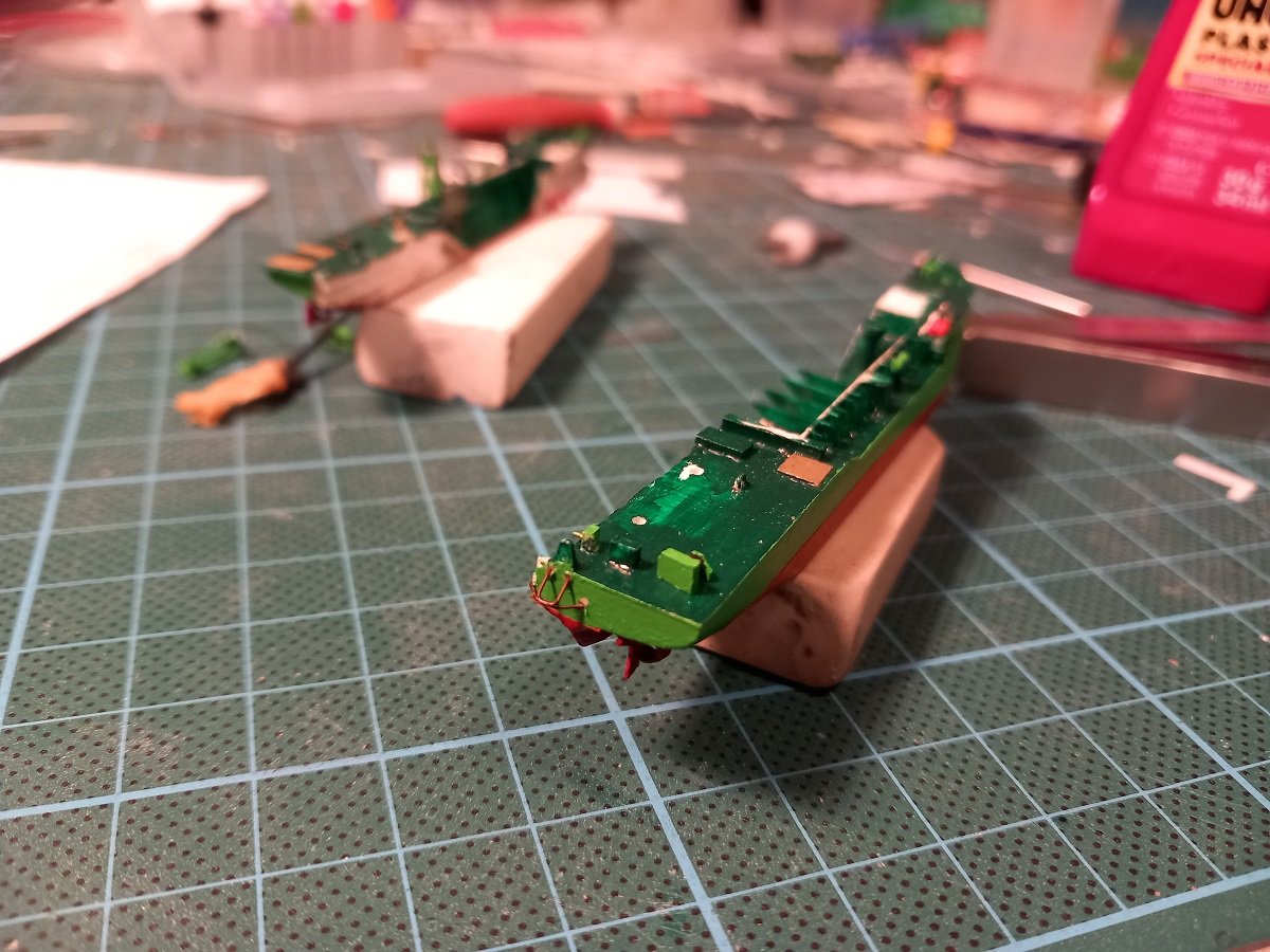
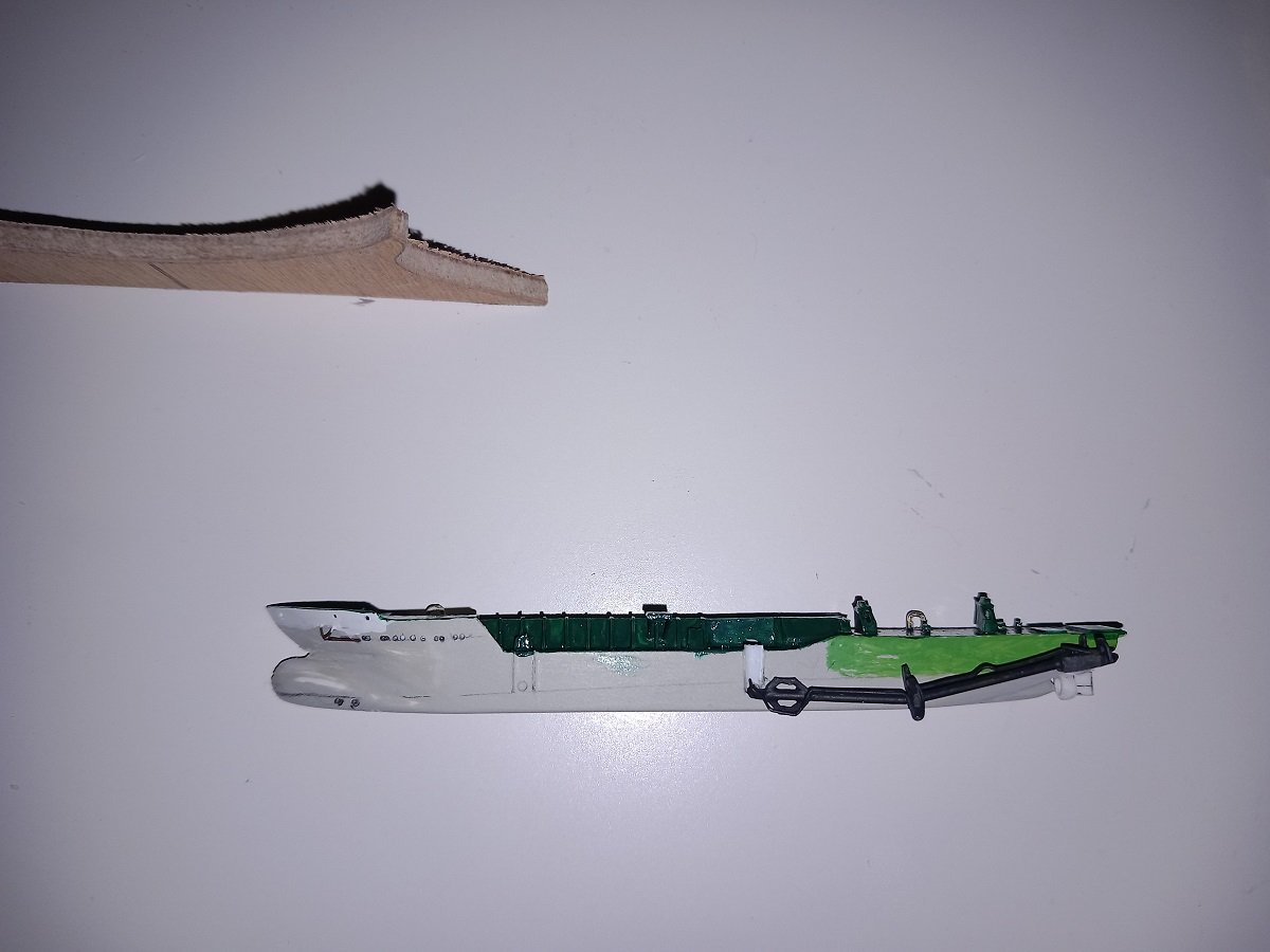
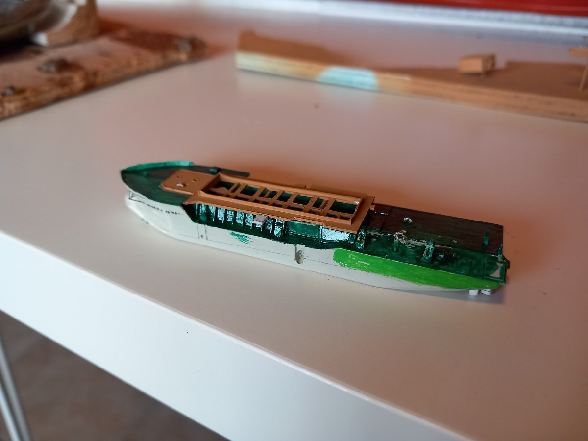
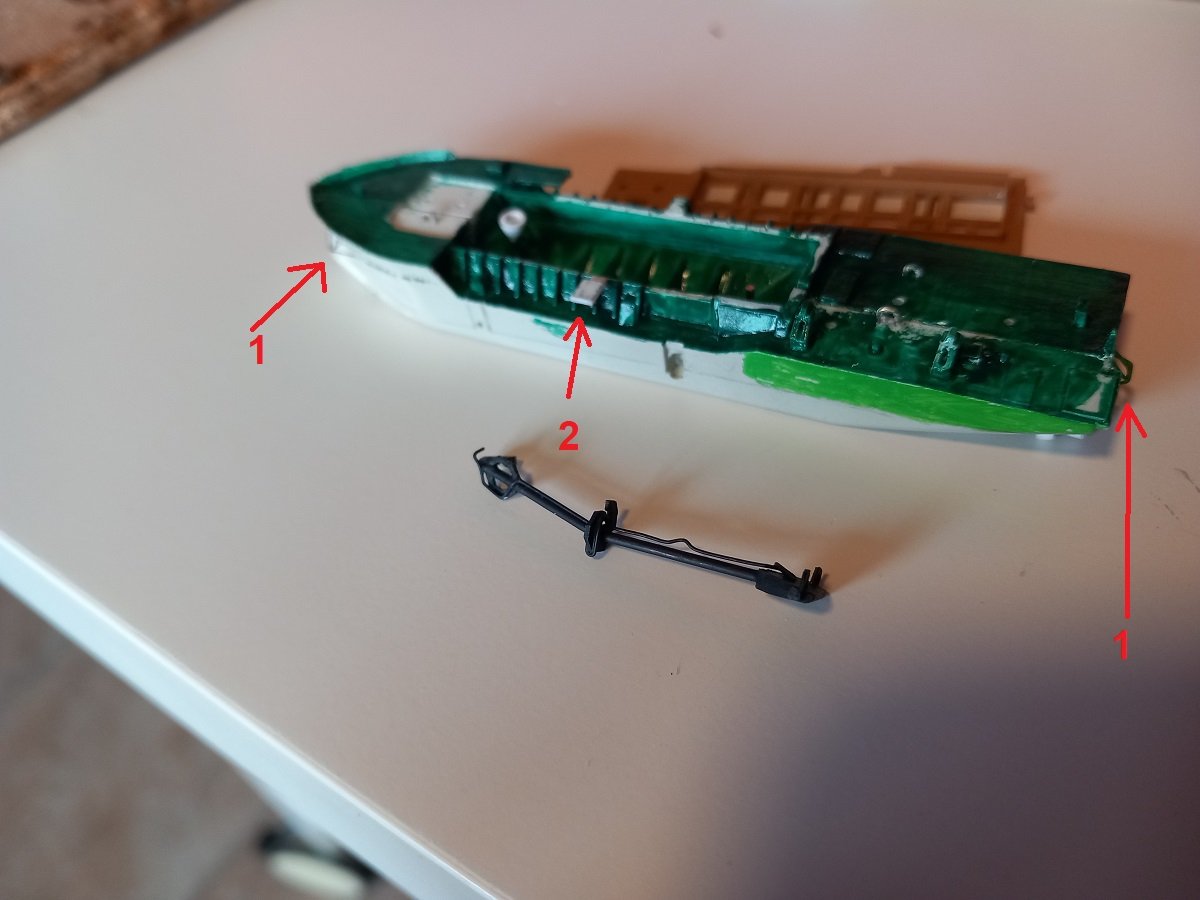
Thanks Keith, The question is not whether I can put those details on, but rather if I want to spend the time on it and whether it's worth the effort, considering the bottle distortion she'll face afterwards. I also used to mix the glossy moss green paint with colourles matt paint to get rid of the gloss, but since she'll be going in a nice glossy bottle, I guess this isn't necessary in this case. Kids back to school from today, so more time to continue. Yesterday I added the steel bar guides for the anchors. Due to her odd bow shape, she needs extensions on the hull to keep the anchors clear of that huge bulb. I build those from copper wire. She also has a riverine/streamer anchor, which they occasionally use in bad weather when picking up the floating line to stay in place. Depends on the dredge operator if he wants to use that one or not. This anchor also has those spacers to keep the anchor from getting stuck underneath the hull. The aft anchor does have a steel wire rope instead of chain (not that it matters that much on my model). The hull is now technically ready for paint. I've also primed the superstructures in order to paint them white after. White doesn't cover well and contrasts from pencil/marker lines are very difficult to hide. The primer takes care of that. And I finally tackled the other thing that I was ignoring, the platform on the PS. I finally cut it off and tested if the deck would fit. It makes a pretty big difference and leave some room to add more detail. Of course I still need that platform, so I fixed that platform to the hull piece. I first glued a smaller plate to have some contact surface to the sloped wall as essentially the platform needs to be at the same level as the deck piece (brown primer in below picture). I also added tiny stiffeners (0.2mm copper wire) to keep that platform level. I also added the two spreader pipes that diffuse the dredged material in the hopper from the top. These pipes I cut at the exact width of the hopper opening, so that they help to position the (brown) deck when I put it in place in the bottle. The seam is unfortunate, but necessary. The platform also has a different colour (gratings) on the real vessel, so in the end there really is a separation. And the overview to make things clear. Numbers 1 are the extensions for the anchors. Number 2 is the platform I'm talking about. Here is is standing free without the brown deck attached. You can also see the painted suction pipe and an effort to match the hull yellow-green. It looked ok during mixing, but I think I'll add more yellow to make it slightly lighter. After finishing the lower accommodation block and painting part of the "brown" deck in moss green, I'll attach the lower accommodation block to that deck. Then I can finally add the dredge line and perhaps valves. At the same time, when I finish the bridge level, I'll be able to glue it to the lower bridge level and that part will be ready.
- 70 replies
-
- 9
-
-
-
- Scheldt River
- Dredger
- (and 2 more)