JacquesCousteau
-
Posts
1,388 -
Joined
-
Last visited
Content Type
Profiles
Forums
Gallery
Events
Everything posted by JacquesCousteau
-
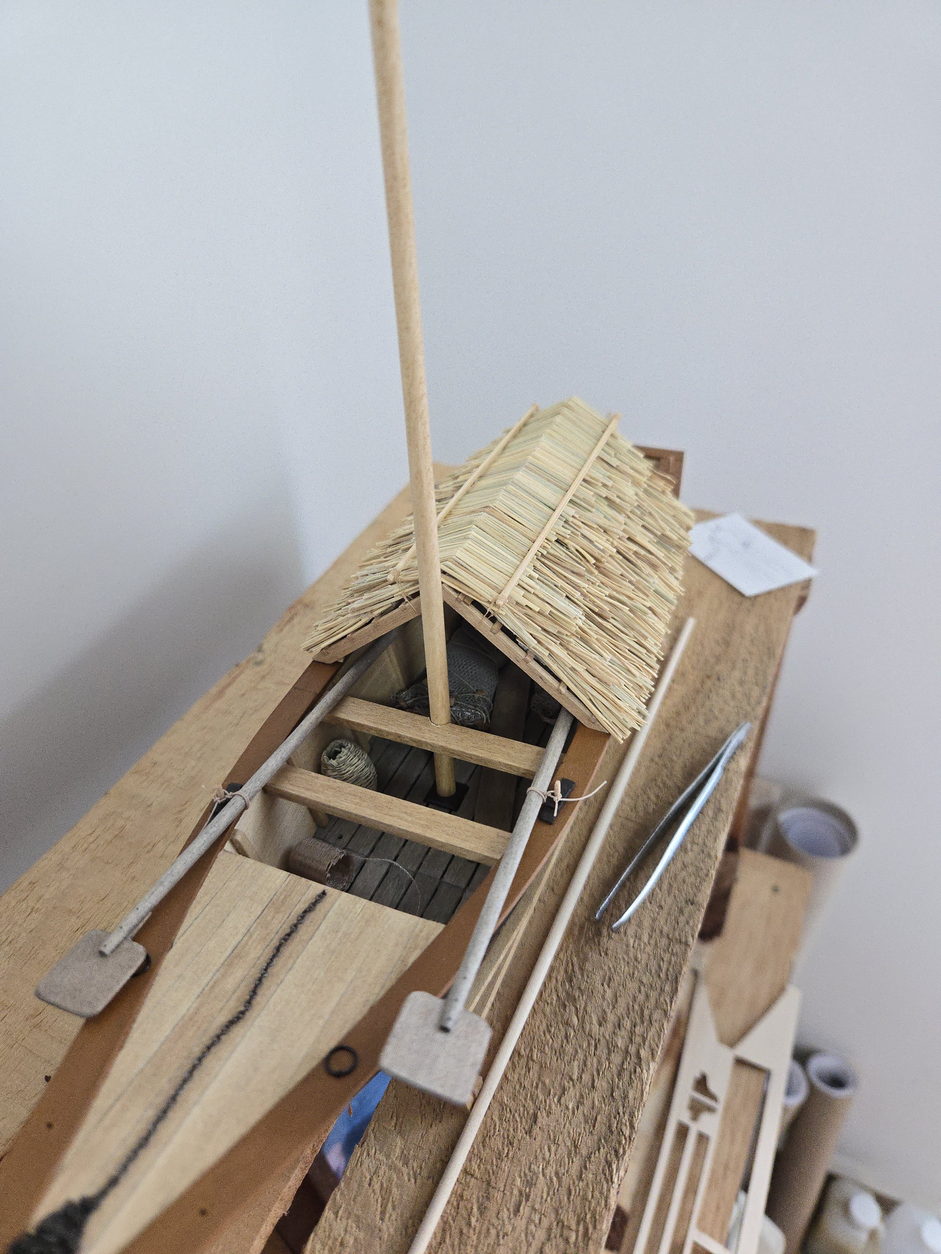
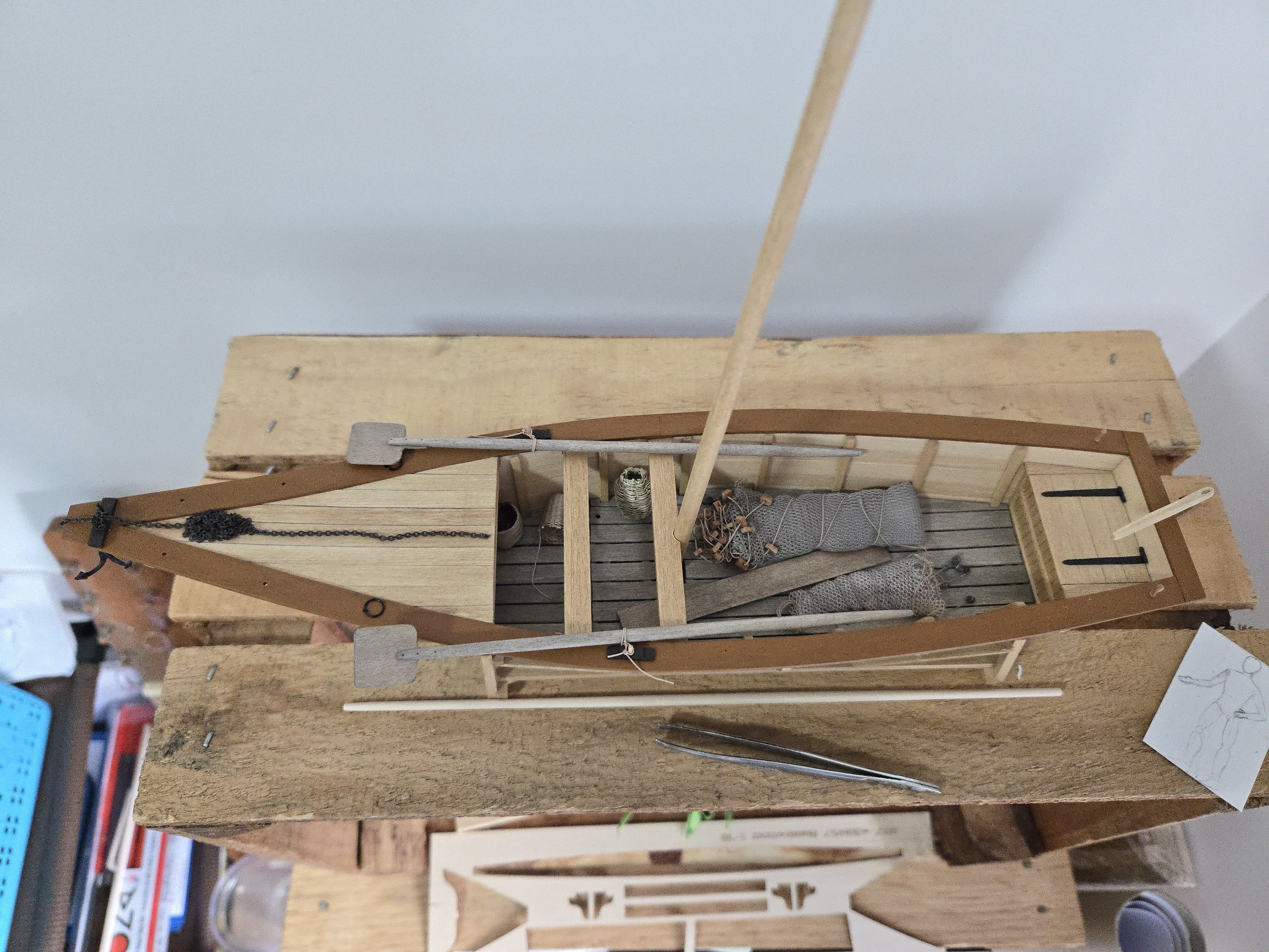
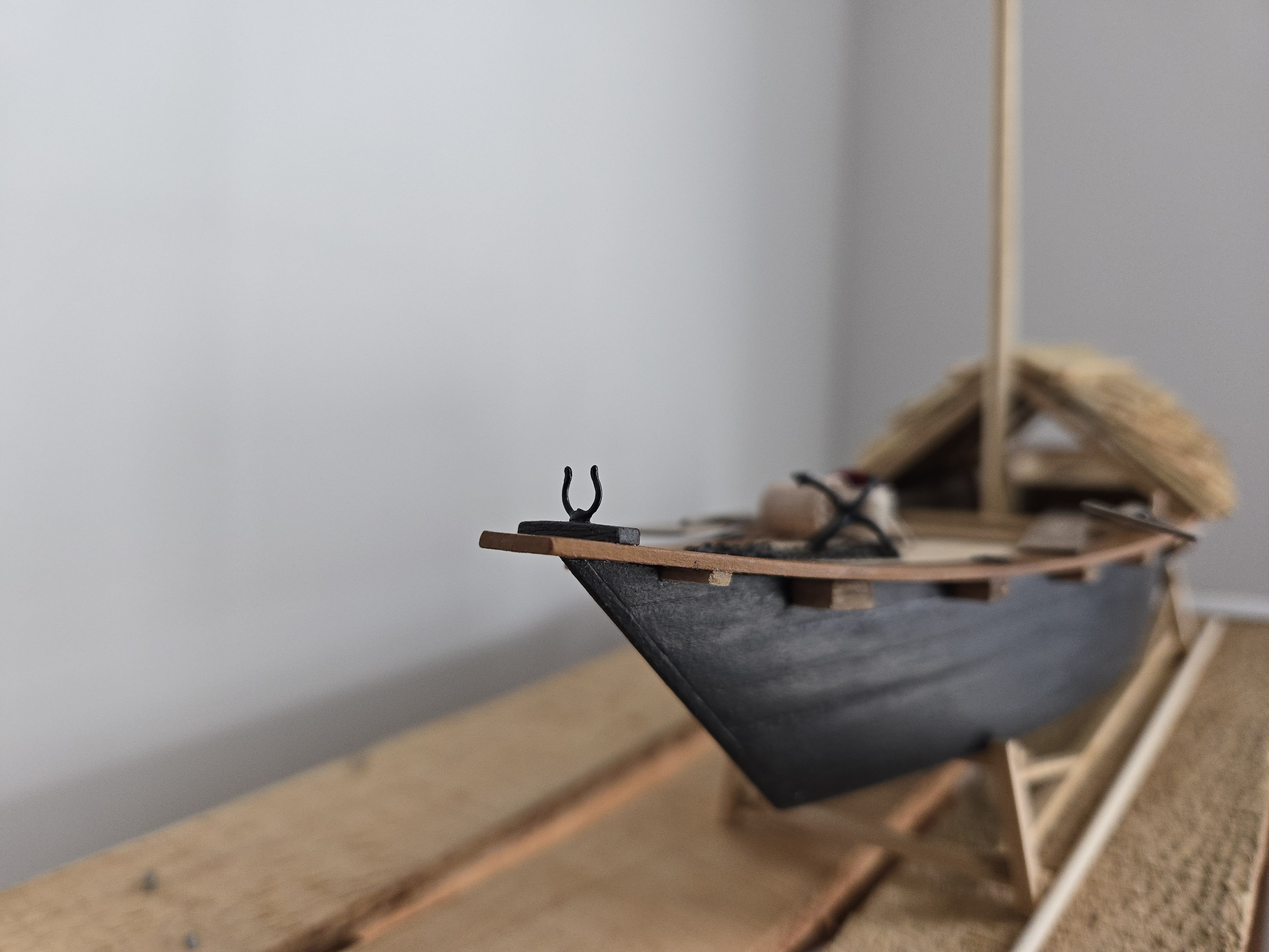
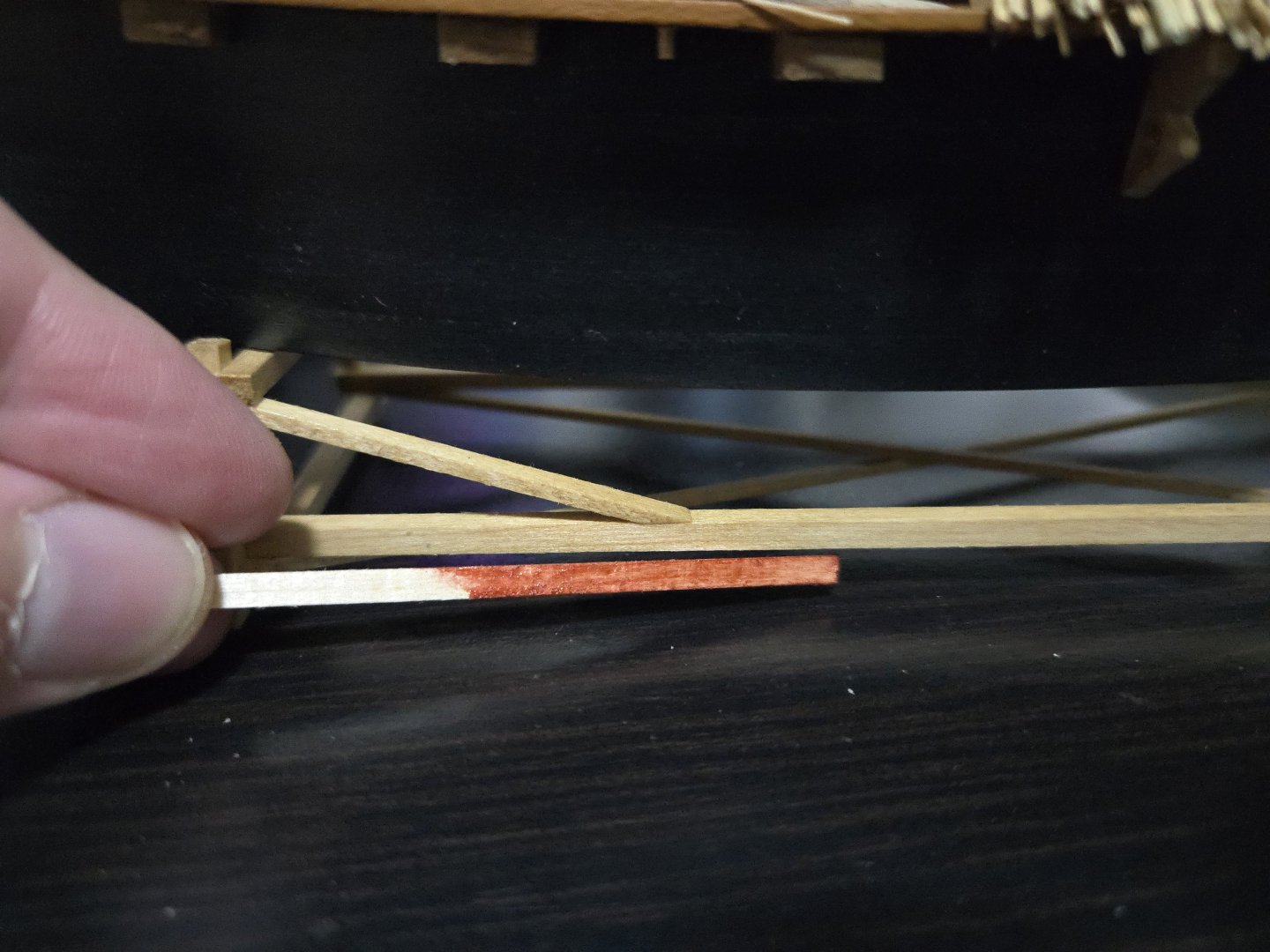
 Definitely! I continue to be a bit blocked by my inability to find a stain that looks remotely similar to what I used earlier. I found one that looked promising, but, perhaps due to the different grain pattern on the yard vs. on my test scrap, it turned out much redder than expected, as seen below. I'll see if I can sand it out, or may have to make a new yard. At this point, frustrating though it may be, I may just have to wait until I visit the US in a month and pick up the proper stain there. In other news, I also wrapped up the fishing nets to store them, using a dab of matte varnish to secure them. In hindsight it was definitely overkill to do as much work on them as I did, given that they're quite hard to see under the rancho. Nothing is glued down yet, as I'm just testing out locations, so I may move them a bit so they're more visible. It's a fine balance between showing them off and blocking the view of the internal structure of the hull.
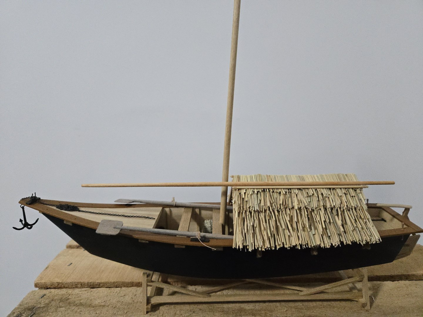


-
Very curious to see how you kit-bashed this one!
-
I had the same issue (as have a lot of people) and found that lining up the fore two slots by trimming the aft end still left the aftmost slot slightly off, which I corrected when I deepened the slots.
- 84 replies
-
- 5
-

-
- half hull planking project
- NRG
- (and 2 more)
-
Congratulations on finishing, nice job!
- 28 replies
-
- 3
-
-
- Lowell Grand Banks Dory
- Shipwright Series
- (and 3 more)
-
Looking forward to following along with this build!
- 84 replies
-
- 4
-
-
- half hull planking project
- NRG
- (and 2 more)
-
It sounds like you've done a good job of figuring out the source of the problem! If you're mainly interested in this build as practice, scratchbuilding some properly-sized thwarts could be a useful skill-building experience.
- 28 replies
-
- 3
-
-
- Lowell Grand Banks Dory
- Shipwright Series
- (and 3 more)
-
I haven't done this build, but my understanding is that they're digital files, so enlarging them shouldn't be an issue. If you're asking whether you need all of the plans in the enlarged scale to build a fully-framed model, yes, as you're planning on modeling practically every part and it won't work if half the parts are in a different scale. If instead you're asking whether you need all the plans right now, it may be useful to think about your build process. As you'll see if you read some build logs, you'll start with the keel assembly and then the frames before getting to other parts. So it may make sense to 1) figure out what scale factor you're using, 2) make sure you note the scale factor so you can scale consistently, and 3) print the plans for just the parts you'll be building first, and print plans for further parts as needed later, making sure to use the same scale factor.
-
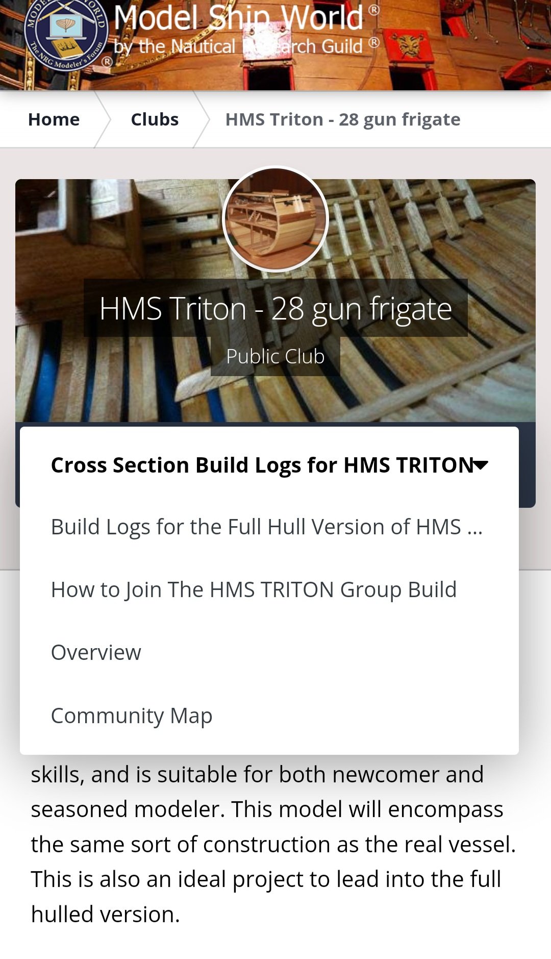
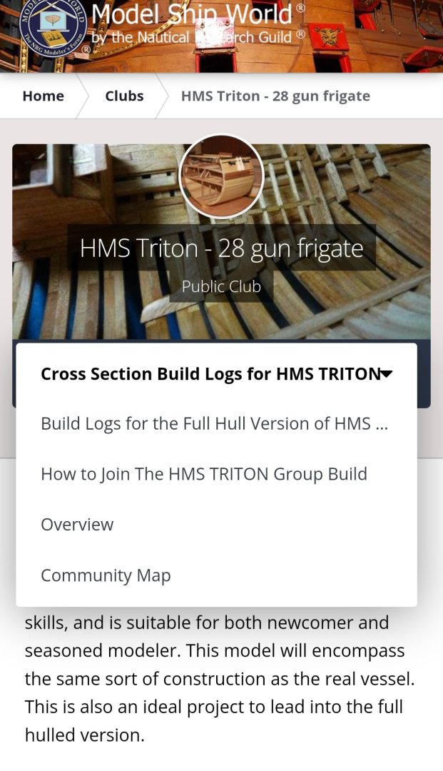
There are full model build logs in the group build. You have to click on the drop-down menu, as shown below, which also will show you other resources. Good luck with your model!
-
@robert952, thank you very much for sharing! That's very interesting information about the buoys. Clearly there's more variety to buoy construction than I was aware of. I have some reading to do before proceeding. Also, although I've read over your log a few times, I hadn't picked up on the buoy being wood in earlier versions of the kit. I have to say that the metal version seems like a bit of a step down to me, although maybe it will look better with paint.
- 65 replies
-
- 2
-
-

-
- Maine Peapod
- Midwest Products
- (and 1 more)
-
The skipjack looks great! So, with your woodworking experience and enthusiasm, I'm sure you'll be able to do a great job on your build. Given the questions that you've had, I think the most useful thing to do now, if you haven't already, is to poke around on this site and read some build logs. I wouldn't limit it just to build logs of big ships of the line, even if that's what interests you most, but build logs for smaller frigates, cutters, brigs, etc would also be helpful. Don't just look at scratch builds, too, as kit builds can also give you a lot of ideas. I've found that build logs for simpler vessels can sometimes be more detailed about things like framing, how to make the curved bow, how to plank, etc, because the more complex builds are often made by more experienced builders who would find step-by-step descriptions of things like that unnecessary and redundant. Reading some clear, detailed build logs with good photos can give you a better idea about how to start, and about what sort of build will work best for you. This site (as well as the NRG) has a ton of great information on it, you just have to go find it. For instance, you asked at the start of this thread how to make the bow D-shaped. It can be hard to explain that just in words, in part because there are a lot of parts that go into that. If you read up on some build logs, you'll be able to see how they frame the bow, fair it so it takes on a smooth shape, and curve and spile the hull planking (which is a much more complex process than it looks at first glance). Checking out build logs is also useful in other ways. For example, Grandpa Phil mentioned the Triton plans, which can produce a beautiful, complex, detailed frigate. It's worth noting that, even with the full set of framing plans available, most build logs for the full ship stalled out at some point or another, often after years of work, simply because such a model is an enormously complex undertaking. https://modelshipworld.com/forum/90-build-logs-for-the-full-hull-version-of-hms-triton/ (Notably, there are a lot more finished logs for the Triton cross-section, which you can see by selecting in the drop-down menu at the link above.) I also just want to reiterate Wefalck's comment that a "challenging build" doesn't necessarily have to be the most complex ship, it just comes down to how much care you put into getting things right.
-
That would certainly be a good way to do it, but I also saw that most lobster trap buoys seem to only have a "tail" coming out of the thicker end, without a protruding part at the front (narrower end) that the kit proposes. So I may just fully fill in the front end.
- 65 replies
-
- 3
-
-
- Maine Peapod
- Midwest Products
- (and 1 more)
-
Thanks! I haven't ever done drybrushing, but I think that would be the way to go about it. I've certainly enjoyed seeing how you approached painting on the Alert.
- 65 replies
-
- 2
-
-
- Maine Peapod
- Midwest Products
- (and 1 more)
-
I'm sure you'll be able to build something you're proud of. The size of the finished model depends more on the scale you choose to build in than the size of the original. You can make a 1-inch-long model of a oil tanker, or a 5-foot-long model of a rowboat, depending on the scale you choose. If you're interested in a warship with guns, maybe a cutter, lugger, or gunboat in a pretty large scale would be a good option. Here, for example, are some plans of a British cutter from 1778, including deck and interior plans: https://commons.m.wikimedia.org/wiki/Category:HMS_Sprightly_(ship,_1778)
-
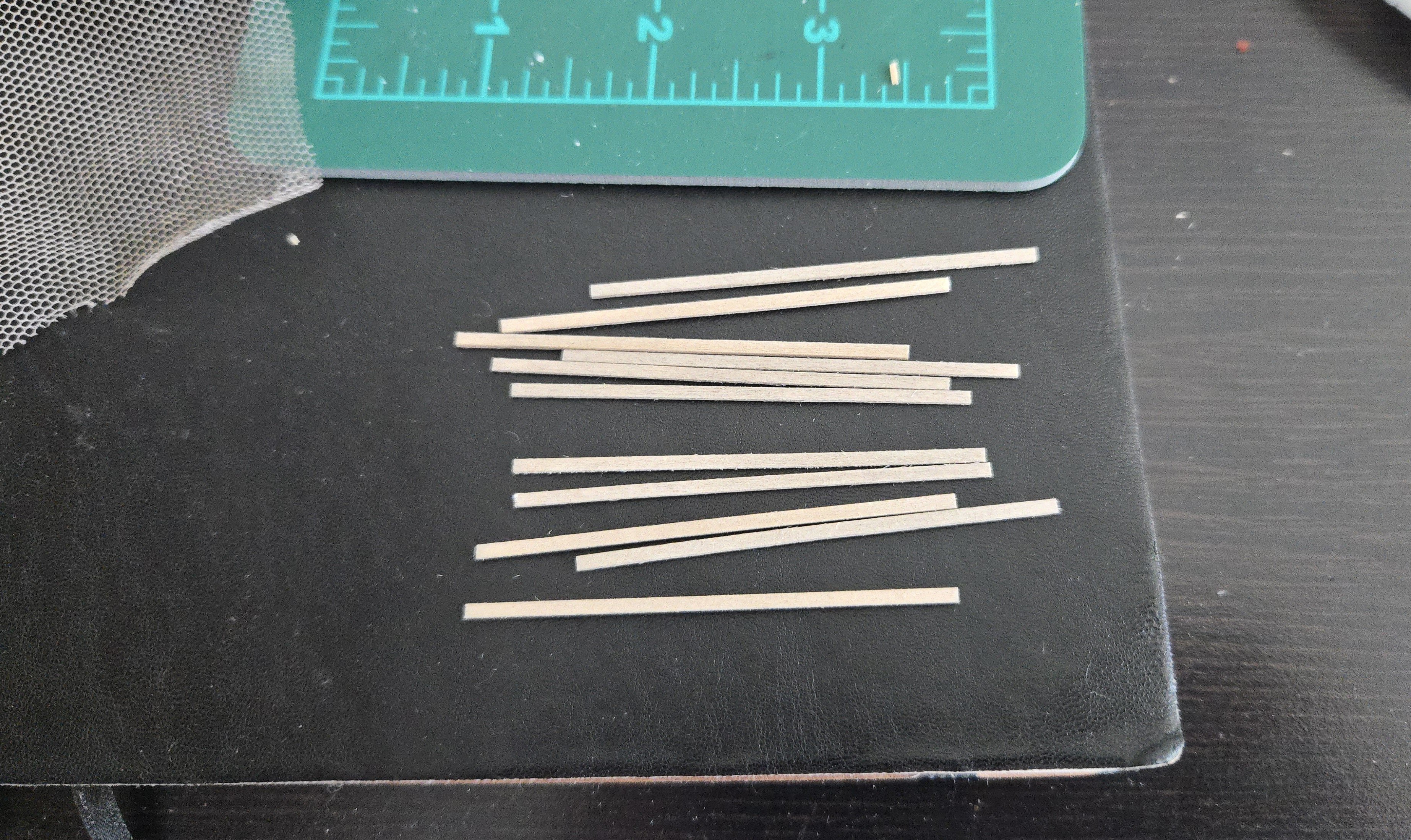
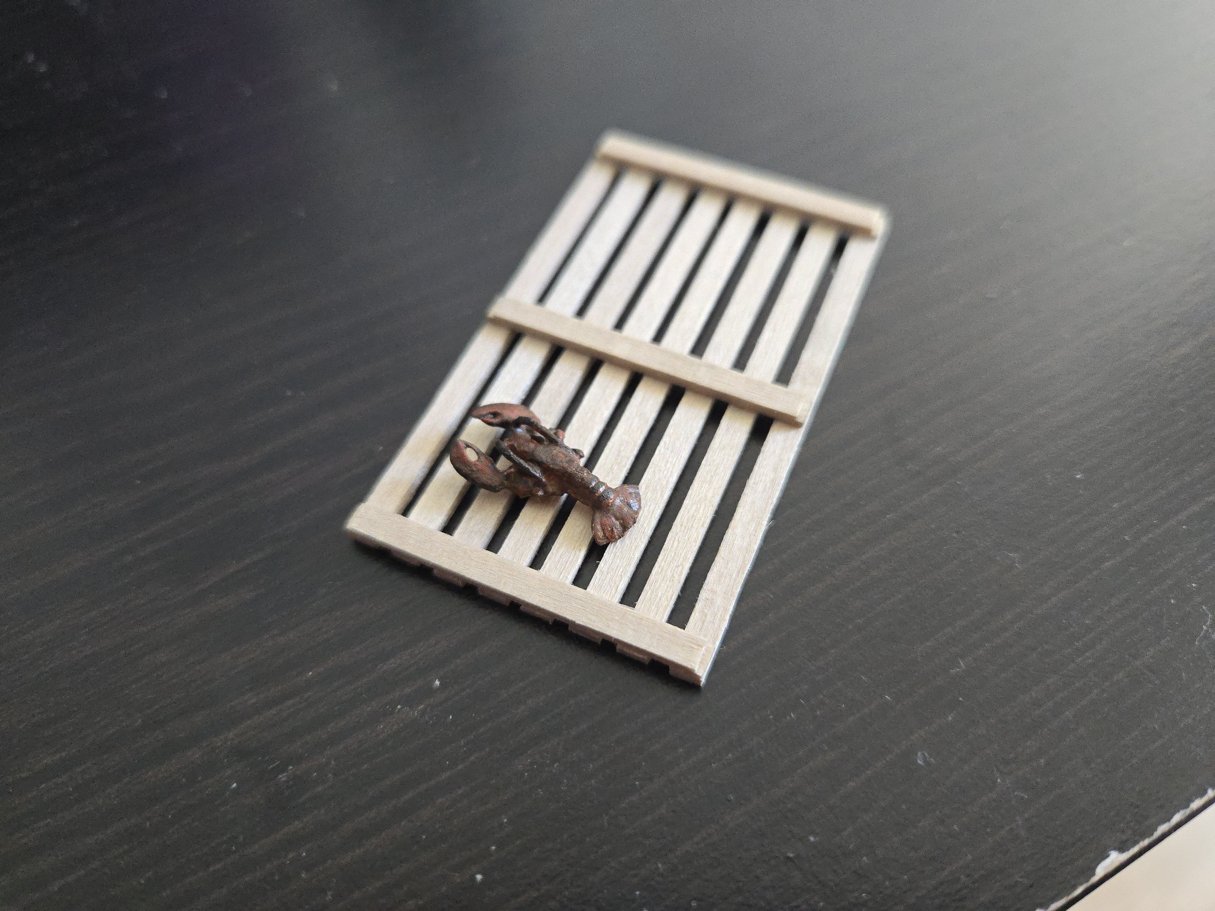
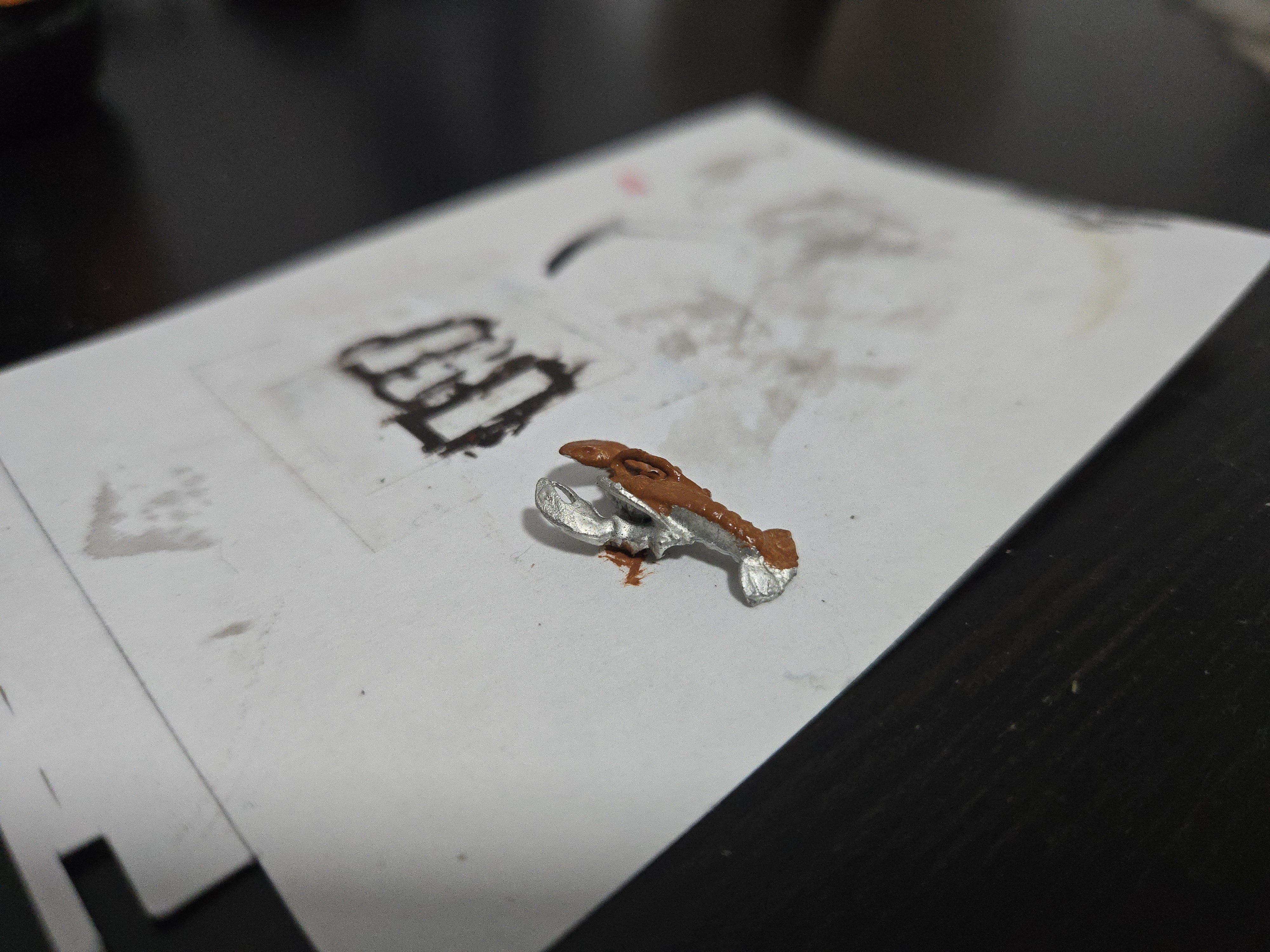
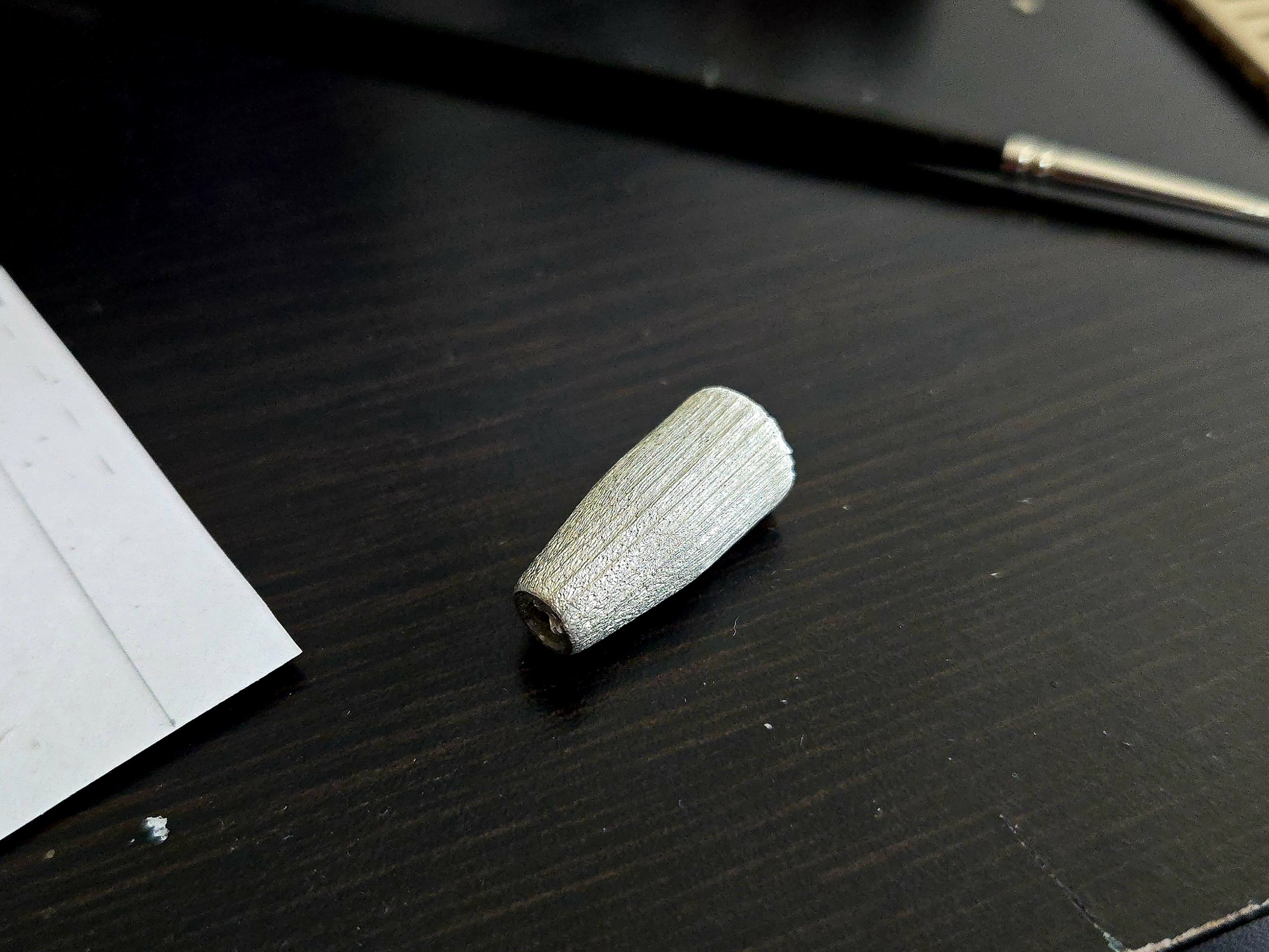
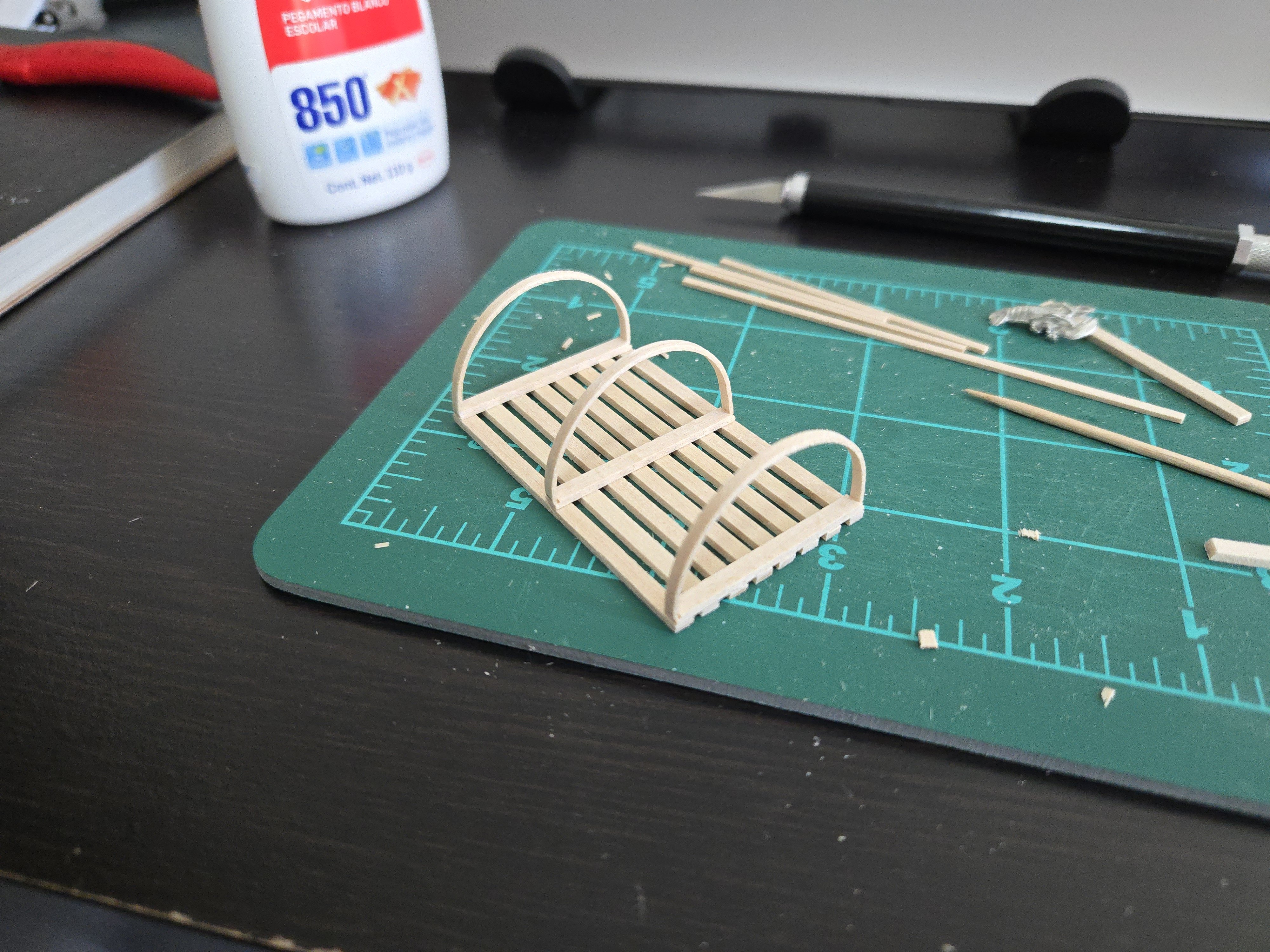
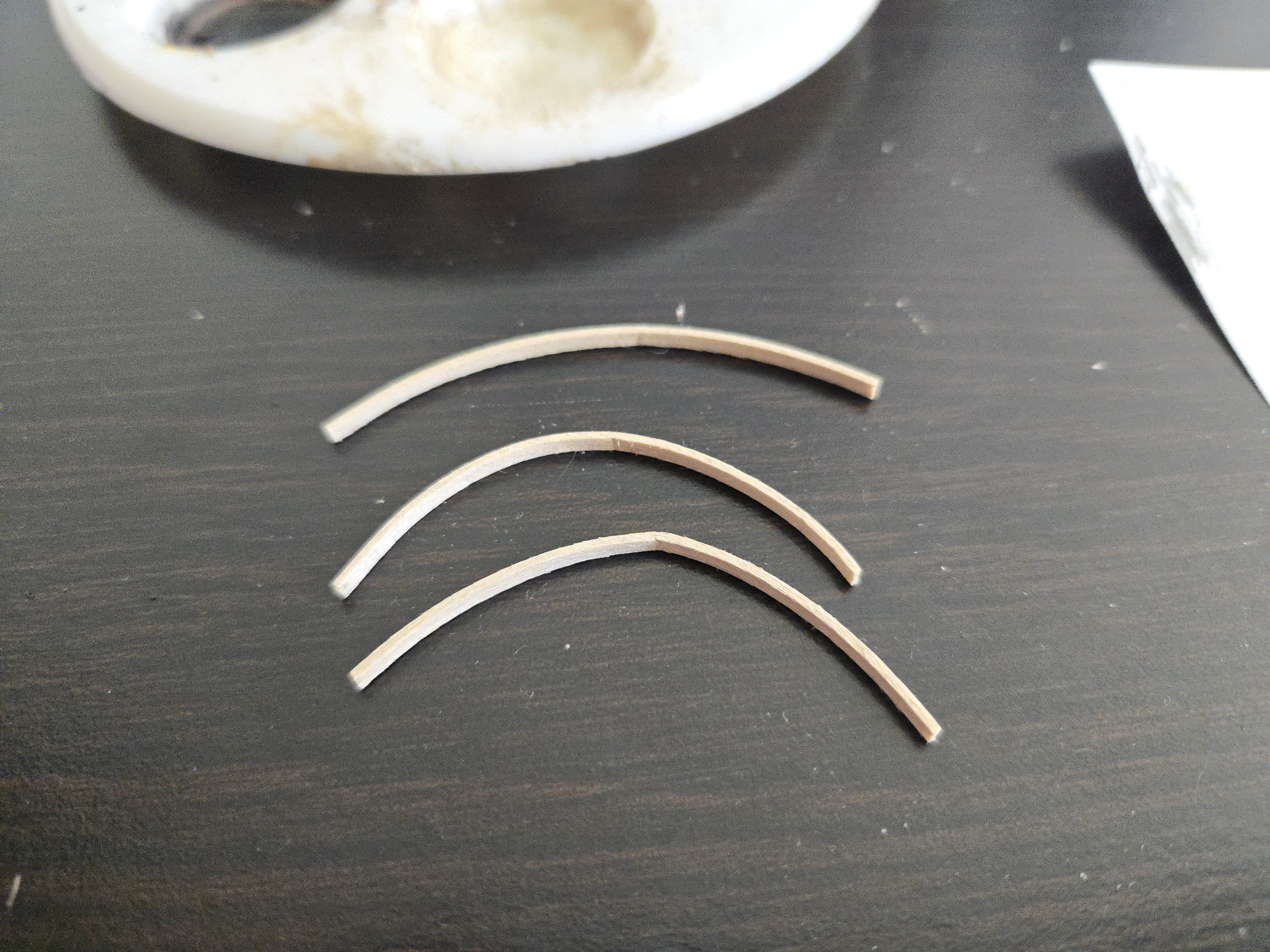
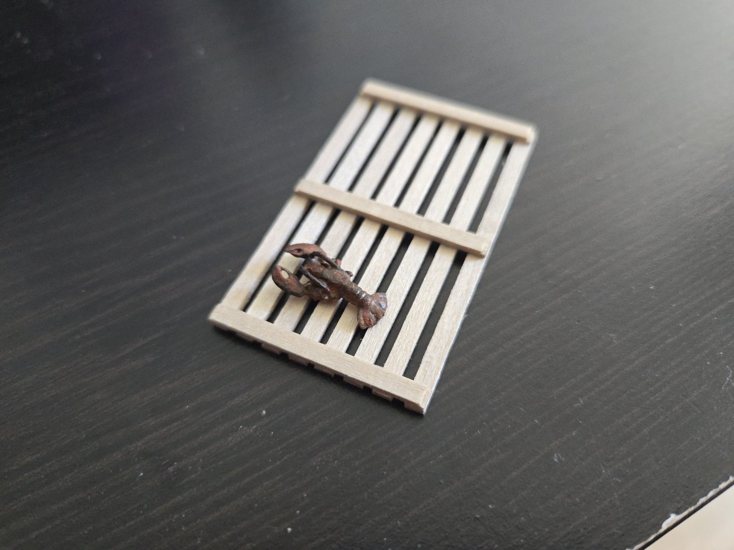
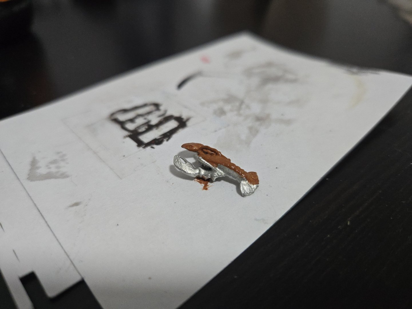
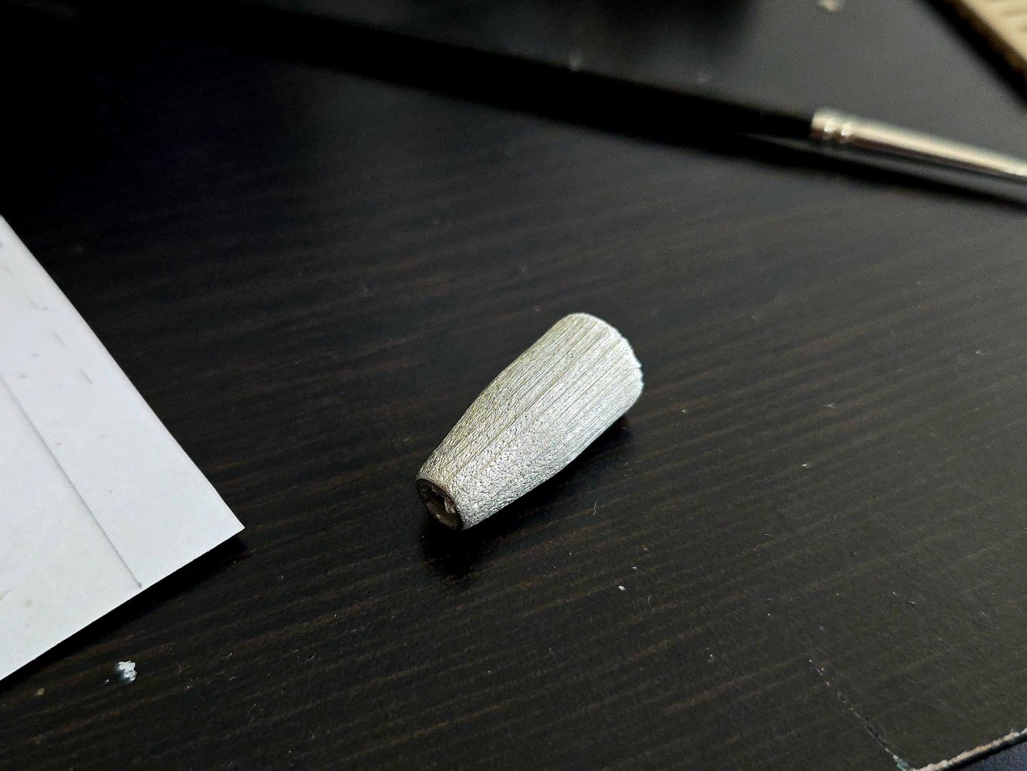
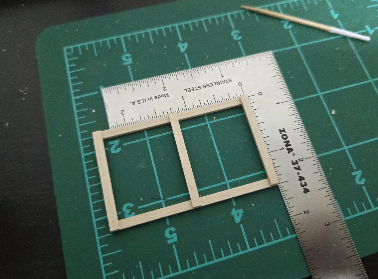
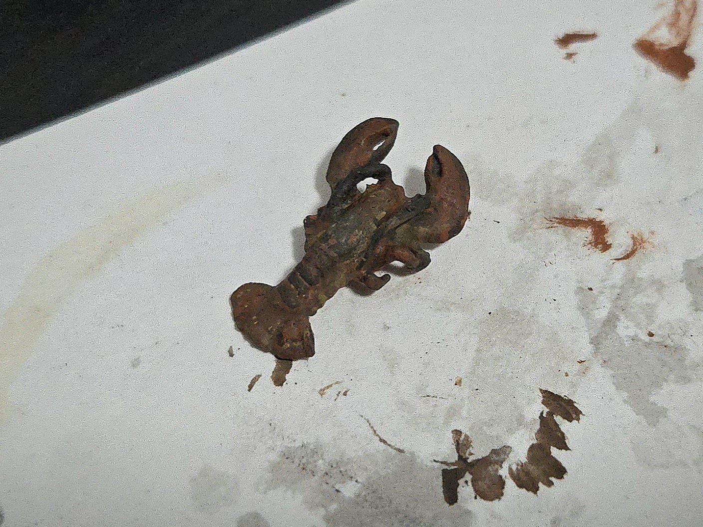
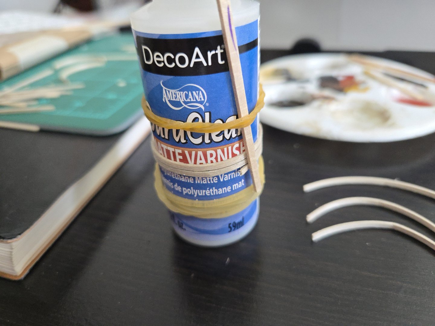
I've decided to slightly change up the design of the lobster trap. Unlike the ones I made for the dory or as a Christmas ornament (which is discussed somewhere in the Canoa de Rancho log), this one will be open on the side instead of the front, and have a few other differences as well. I am not following the plans in the kit, which seem a bit inaccurate. I started with the base: I then added the loops. So far, so good. I decided to color the trap with a very light black wash. I decided against really weathering this build, so I don't want the trap as heavily weathered as the others I've made, but completely bare wood didn't look right. Unfortunately, applying the wash made the loops fall off, as they were not very securely glued, and some broke when I tried to bend them back into shape. I should have seen this coming, as I had a similar problem with the dory's trap. In any case, I made new loops, this time applying the wash and letting it dry before I curved it around a varnish bottle with hot water: I also began pre-washing the slats: I'm planning on having the top of the trap open, because the kit includes a delightful tiny cast metal lobster (which I forgot to photograph until I was in the middle of painting) that I want to place inside. As can be seen, some details are a bit lacking--some of the legs are just a lump, and that's after I attacked it with files to try to add definintion. Unfortunately my figure painting skills are woefully lacking, and the mottled coloration of real lobsters was hard for me to capture. After a lot of effort with mixing paints, my results are... not great, I guess it doesn't NOT look like a lobster. It looks better from farther away, and after getting a slightly glossy sealer coat. Finally, the kit also includes a cast metal buoy with excessive faux wood grain. I'm not sure why it doesn't have you just make a wooden buoy, but the casting doesn't seem heavy enough to serve as a useful weight, so I think I'll use it anyway. There's a hole running through the center of the casting, and I'm supposed to shove a 1/8‐inch square stick of basswood through there. The hole is round, so the basswood will only fit if the edges get cut down, which I don't think would look right. I'll fiddle around with this and decide on what to do.


- 65 replies
-
- 7
-
-
- Maine Peapod
- Midwest Products
- (and 1 more)
-
You mentioned that you want a challenging build, but it's worth noting that even a smaller vessel, built with care, is still a huge challenge. Here, for instance, is a fascinating build of a fishing schooner at about the level of detail you're proposing. The builder had to loft the frames from the plans. As can be seen, it took about three years.
-
I think that what people are trying to suggest is that it's not so much the plans, as it is the sheer scope of the very ambitious project you're proposing to take on. I could be wrong, but I don't think you're going to find a plan set that includes detailed diagrams of all the parts of a major warship like you're interested in, unless you buy something like an Ancre monograph. Others who are more knowledgeable about this can correct me if I'm wrong, but historically, plans sent to the dockyard for construction did not include such details, and the frames needed to be lofted--that is, diagrammed out--individually based on the stations on the plans. So, to make what you're proposing, you'll need to figure out lofting, unless you get a monograph with everything already diagrammed out. Once you do that, which is itself a huge undertaking, you'd be able to start cutting wood, but getting everything precisely lined up and set is a huge project. You can see this if you browse some of the build logs on this site (search "POF" and you should find some). A fully framed model of a major ship of the line is a project that can very easily take a decade, will inevitably have frustrating setbacks, and has a lot of tedious parts as well (like making several hundred tiny block-and-tackle setups for the cannons). This will be the case even if you opt for a simplified, stylized framing structure. People are suggesting that you start smaller not because they want to discourage you from the hobby, but because they want to see you succeed, and the best way to do that is to not start by trying to do a complete first-rate ship of the line. Would a smaller warship at all interest you?
-
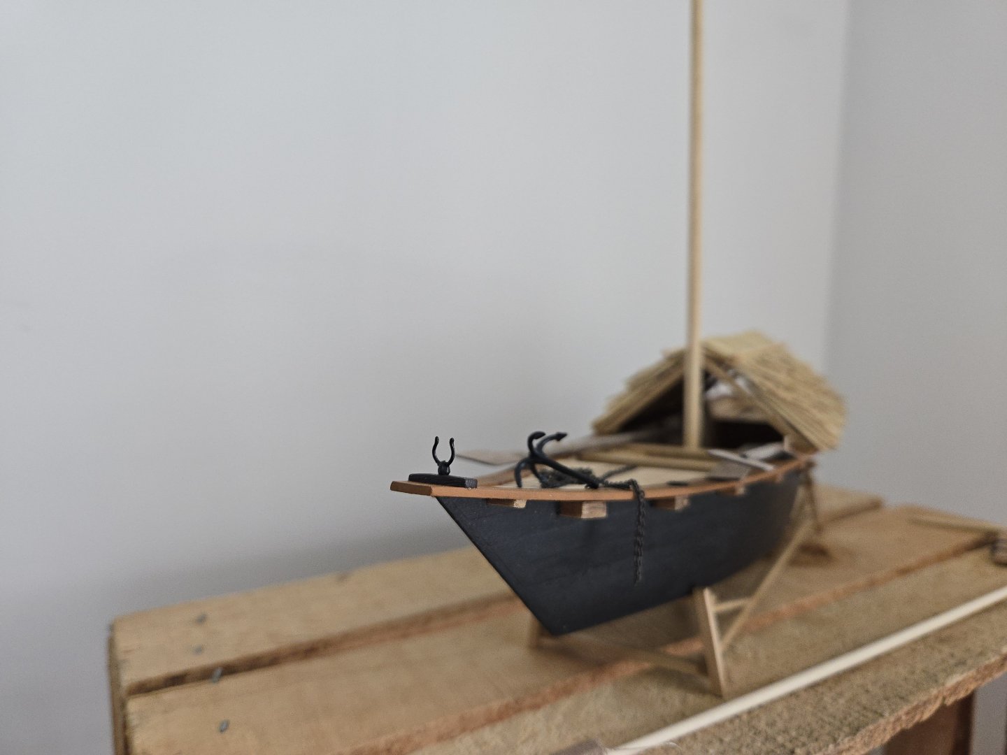
A brief update. Unfortunately, the build has slowed due to some difficulties in getting materials and a very busy periodat work. For the sail, I haven't had the chance yet to look for screen-print silk. On the other hand, if I go the coffee filter route, I'll need a large size, #6 coffee filter instead of what I already have, but they only seem to come in packs of hundreds. I may see if a local café would be willing to sell me a filter or two for a few pesos instead. I also have had some difficulties in getting the right stain, which I need for the yard. The mast (and foredeck, and some other parts) had all been stained with a Minwax Golden Oak stain pen, which unfortunately ran out. I forgot to pick up a new pen before the move, and am finding that either the stain pen or a can of it are hard to find here and very expensive. I picked up a small can of a different stain that claimed to be "Light Oak," which sounded like it would at least be close enough. But when I tested it, it turned out to be weirdly red (as seen below, compared against the Golden Oak-stained stand). So, I need to visit some hardware stores and try to find a stain that's a closer match, but I haven't had much time to do so lately. It's not all bad news, though. I wasn't totally happy with how the anchor support ring turned out, as it was too tall, so I cut it off, reshaped it, and glued it back on. A small thing, I know, but I think it looks much better now. Below is the original followed by the redo. Original: Redo:

-
There are a lot of options you can look at in the Build Logs-Scratch Build category (https://modelshipworld.com/forum/151-build-logs-for-scratch-projects-by-era-launch-date/). KLarsen himself has a completed POF build of a small fishing boat, the Santa Caterina, which shows just how complex even a relatively simple vessel can be. He's also working on a POF build of just the stern of a frigate, La Mahonesa, which really shows the complexity of a sailing warship, while still being a smaller, simpler vessel than a ship of the line. (If you search for the ship names, you should be able to find the build logs pretty easily). For another example, again of a simpler vessel than your plan, see: https://modelshipworld.com/topic/19253-le-gros-ventre-by-marsalv-finished-148-pof/ It's also worth noting that all of these builds are based on monographs that include detailed diagrams of all the frames and other parts of the hull. Making a POF model from just the plans you've shown would require, as others have noted, would require a lot of working out frame shapes and the shape and dimensions of a lot of parts that don't appear on the plans, which would require a lot of research into the nuts and bolts of Napoleonic-era shipbuilding. It's up to you what you want to do, but it's worth noting that what you're proposing is a truly massive undertaking.
-
Great job repairing the bulkheads, the framework looks great! On the planking, as you note, you have two options. The method given in the instructions is not accurate to how boats are actually built, but as you've seen, the end result can still look quite nice. The other method will require more work but is more accurate. That said, I don't think you'd need a stealer between every full plank. Rather, you'll need to taper each plank substantially at the bow, possibly close to the half-width limit (the exact size is something you'll have to determine with measurements). You'll also need to edge bend the planks such that they curve downward toward the bow. I haven't ever edge bent planks, but if you look at my Half-Hull build linked to in my signature, you can get a sense of what planks should look like as they approach the bow. I just cut them in that shape from a sheet, but you can get the same results by edge bending a tapered strip. If you keep looking around on this site, you'll be able to find lots of examples of edge-bending that should be helpful. All of which is to say, it's up to you which method you want to go with, both can look nice. Personally I find it fun to try to recreate accurate planking, but I wouldn't begrudge anyone for doing it the other way, especially for their first build.
- 19 replies
-
- 1
-
-
- Bounty Boat
- OcCre
- (and 2 more)
-
Congratulations, you did a great job! I love how you displayed it with the oars in action. Looking forward to your next build!
- 12 replies
-
- 2
-
-
-
- Lowell Grand Banks Dory
- first build
- (and 1 more)
-
That's great! One of the benefits of working with wood is that it's possible to reshape and repair a lot. I found that bobby pins worked well as clamps, providing enough pressure to hold the wood in place without breaking it.
- 28 replies
-
- 1
-
-
- Lowell Grand Banks Dory
- Shipwright Series
- (and 3 more)
-
Looks like it's coming along nicely! Not to be overly critical, but one thing you may want to watch out for is how you're clamping the planks at the ends. Due to the difficulty of clamping there, it's very easy for the planks to end up pressed inward, causing a sort of bottleneck shape that looks off and can make it hard to fit the cap rail.
- 28 replies
-
- 4
-
-
- Lowell Grand Banks Dory
- Shipwright Series
- (and 3 more)
-
Congratulations, the model looks great! It's interesting to see the differences with the Model Shipways kit, too.
- 56 replies
-
- 2
-
-
- grand banks dory
- Midwest Products
- (and 2 more)