


yvesvidal
-
Posts
3,489 -
Joined
-
Last visited
Content Type
Profiles
Forums
Gallery
Events
Posts posted by yvesvidal
-
-
I can almost picture myself, during one of my former incarnations, walking around that cloister while reciting an endless litany of "Pater Noster".
Great job.
Yves
- Ekis, popeye the sailor, Canute and 2 others
-
 5
5
-
Small but beautiful collection.
Yves
- thibaultron and Duanelaker
-
2
-
46 minutes ago, RGL said:
this is why PE is really unbeatable
PE and a seasoned artist and expert at PE.
Yves
- Canute, Javlin, popeye the sailor and 4 others
-
7
-
Le Saint Philippe at the scale of 1/48..... WOW !!!! Major endeavor.
I will be following.
Yves
-
For a first attempt, it is lovely. Fantastic job.
Yves
-
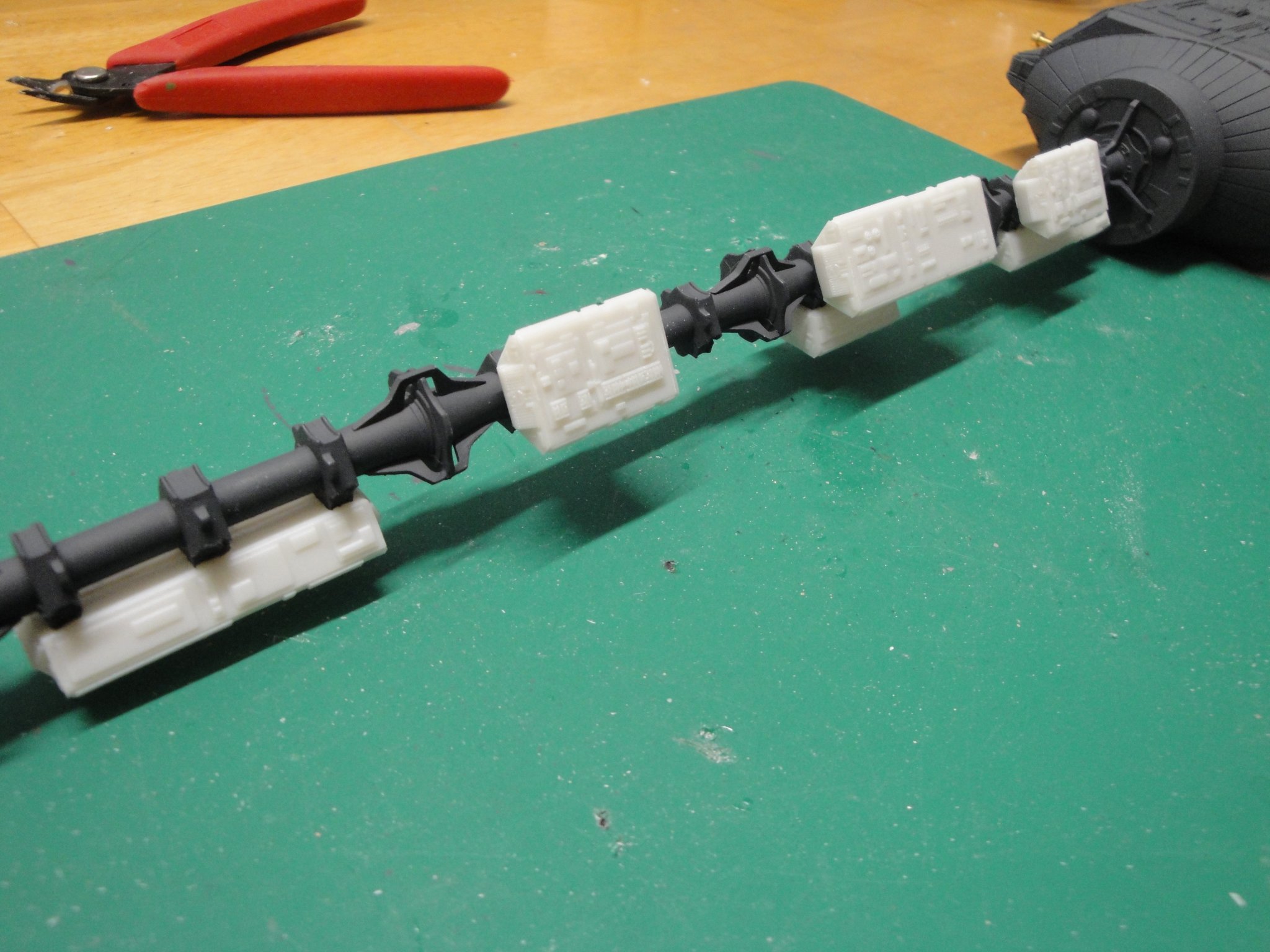
I am working on the cargo pods of the rear spine. Assembly of the A (long) and B (medium) types has been completed and installed:
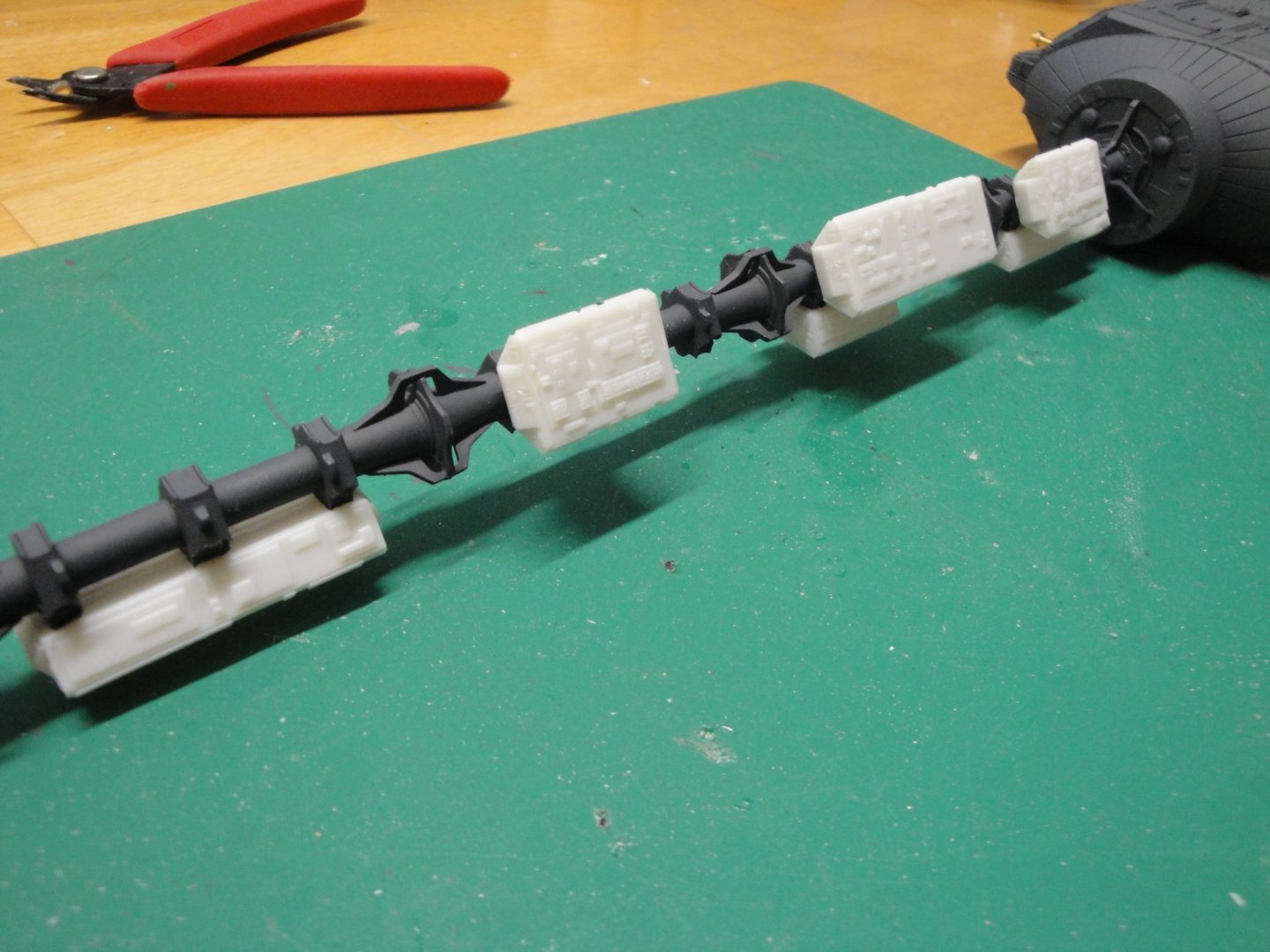
It is important to be very methodical with these Pods as parts can be easily mixed up.
Yves
- lmagna, GrandpaPhil, Canute and 8 others
-
11
-
So, Christian, what is the next project on your list? Another vessel designed by Chuck P. or something else?
Yves
-
17 minutes ago, popeye the sailor said:
does this include decals? if not....have you looked at decals for Star Trek, or Star wars models........perhaps something along these lines could give it more exterior detailing.
Popeye,
No decals on this kit as the original prop from the movie did not have any.
For more exterior "contrast", the AZTEC set provides some masks that add "camouflage like" patterns to the vessel. I am not a big fan of these and like the Stanley Kubrick's purist lines of the Discovery. I will paint some panels as in the movie, but will stop there. No weathering either, as there is no air, and very little dust to attach to this kind of machine in Space.
Yves
- GrandpaPhil, Canute, lmagna and 3 others
-
6
-
Superbe realisation Christian. Bonne Annee et bonne sante a vous.
Yves
-
Very Roman looking. Beautiful.
This will be a heavy diorama, when completed.
Yves
- popeye the sailor, mtaylor, Canute and 1 other
-
4
-
Propulsion block more or less completed. The only things remaining to be done are the exhaust plates with the PE grills.
In the meantime, I have sprayed the sub-base using Tamiya German Grey:
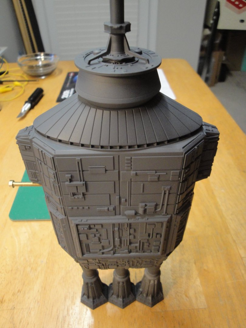
Hopefully, this color will provide some depth and delineate the various panels, when spraying the light gray and white on top.
Yves
- GrandpaPhil, hexnut, Dubz and 10 others
-
13
-
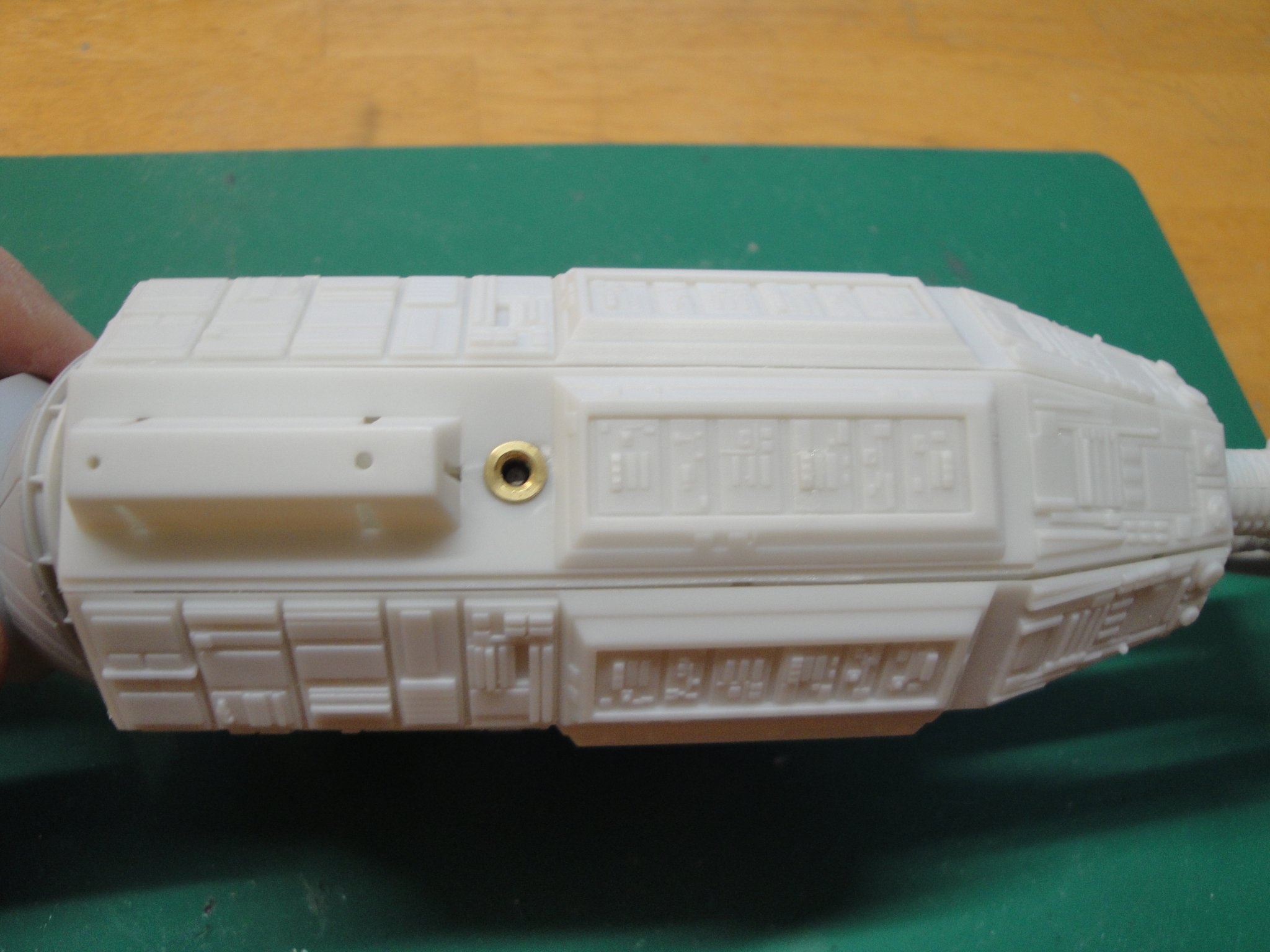
Moving along with the completion of the propulsion block. Lots of parts, but the fitting is exceptional. This kit is very well engineered.
This is the anchor which will be used to hold the model from the rear and to feed the negative side of 12 VDC. It is a 3 mm special nut. I will try to show a picture of the part, later on.

Yves
-
Thank you for the very clear explanations about your technique. This craft looks stupendous. Those French have a way to decorate their planes that is quite unorthodox. Blame it on the sun and blue sky of Provence.....
Yves
- popeye the sailor, mtaylor, CDW and 3 others
-
6
-
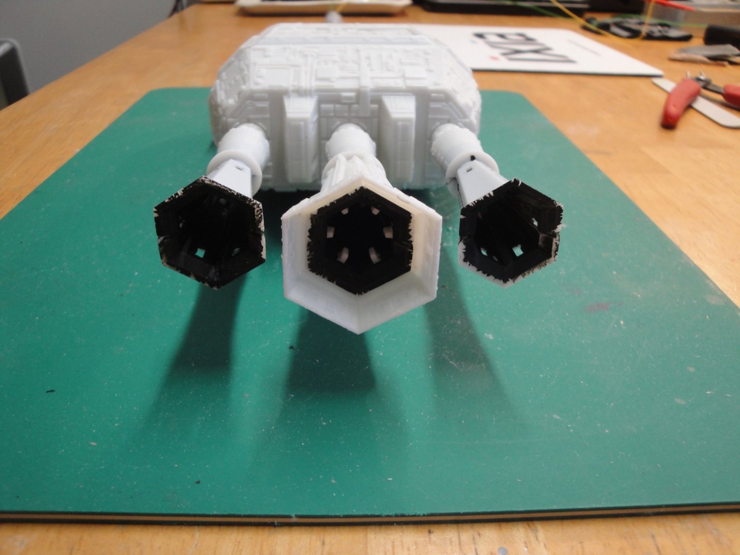
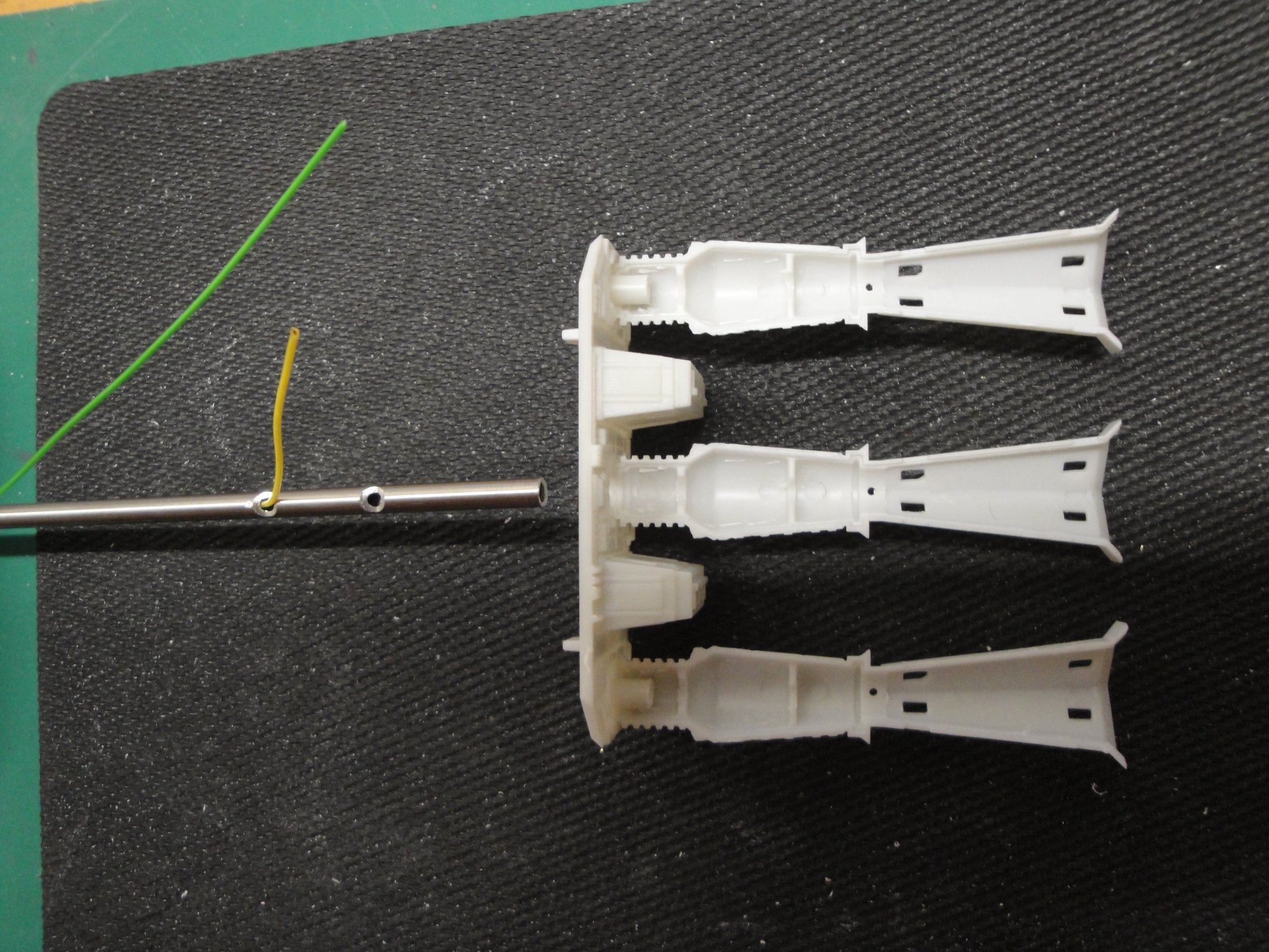
The thrusters are almost complete. Inside each one of them, there is a flickering yellow LED. After trying these LEDs on my bench, I realize that the current drawn by each one of them, varies constantly because of the flickering. Therefore, they cannot be serialized or daisy chained. They operate at around 3 volts, under 10 mA each. Since the whole enchilada will be powered with a source of 12 Volts DC, it is necessary to drop about 10 Volts in a resistor. 1 KOhms is perfect for that purpose.
First, the lower shell of the rockets are glued on the rear bulkhead:

The main rod is being opened in three places: Ground wire, Plus wire and the two tiny wires leading to the central LED. The holes are done with a round file, then semi-round and finally a bit of 2 mm, to provide a less sharp opening for the wires.
The rear bulkhead has been reworked: pins on each side, have been shortened and drilled to allow wires to go through. The inside of the thrusters is painted black, to simulate the intense heat and combustion taking place in them.
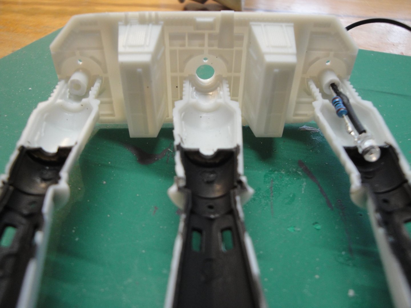
Wiring is neatly arranged, as much as possible. None of the plastic parts are glued yet....the wires are holding everything together.

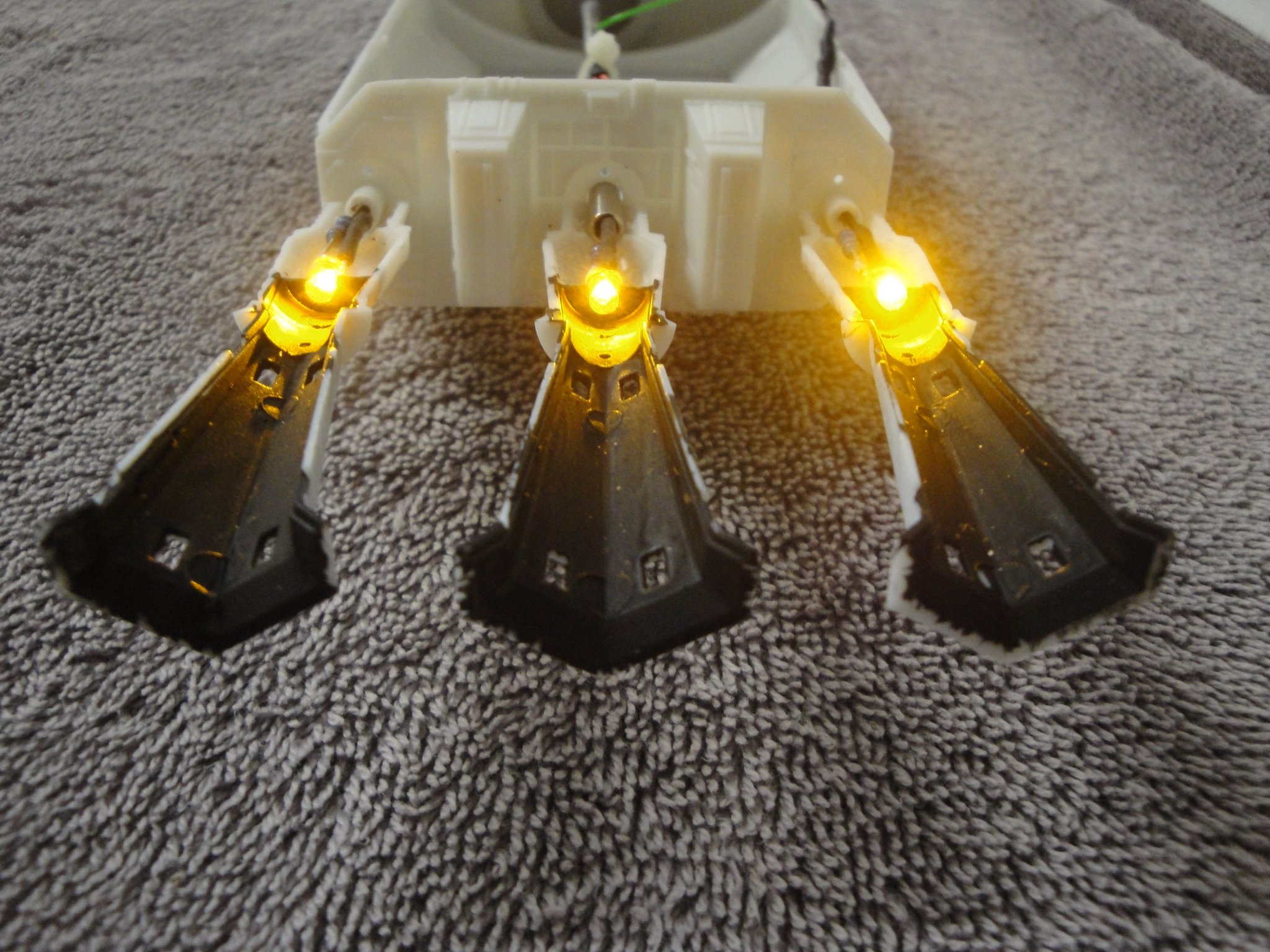
The lug on the top of the picture (right side of the engine block) will be the negative side of the holder. The green wire brings the - to the front module, through the rod. The yellow wire feeds the rear engine block with the + side, coming from the holder that will be located near the front sphere or living quarters of Discovery. Verification of the diodes:
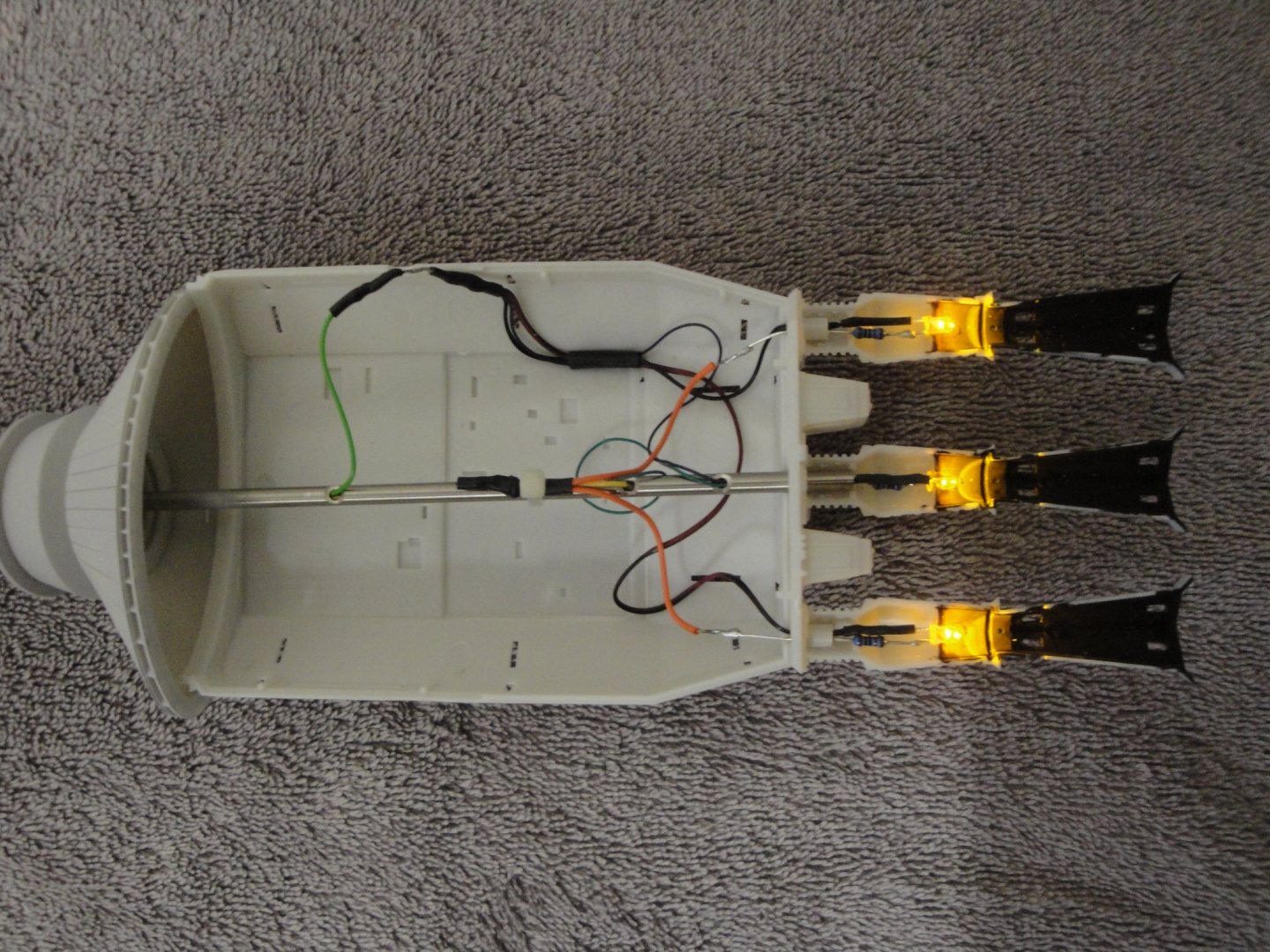
It flickers well and provides a sense of these atomic reactors being ignited by HAL 9000, to complete his precious mission....with or without anybody alive....

Yves
-
Could you elaborate on how you did that treatment?
Thanks
Yves
- Old Collingwood, mtaylor, lmagna and 3 others
-
6
-
4 hours ago, hof00 said:
How long is Discovery?
Close to 42 inches at that scale.
Yves
- thibaultron, mtaylor, hexnut and 2 others
-
5
-
This paint job is superb. We all know how glossy paints can be difficult to spray correctly and regularly.
Yves
-
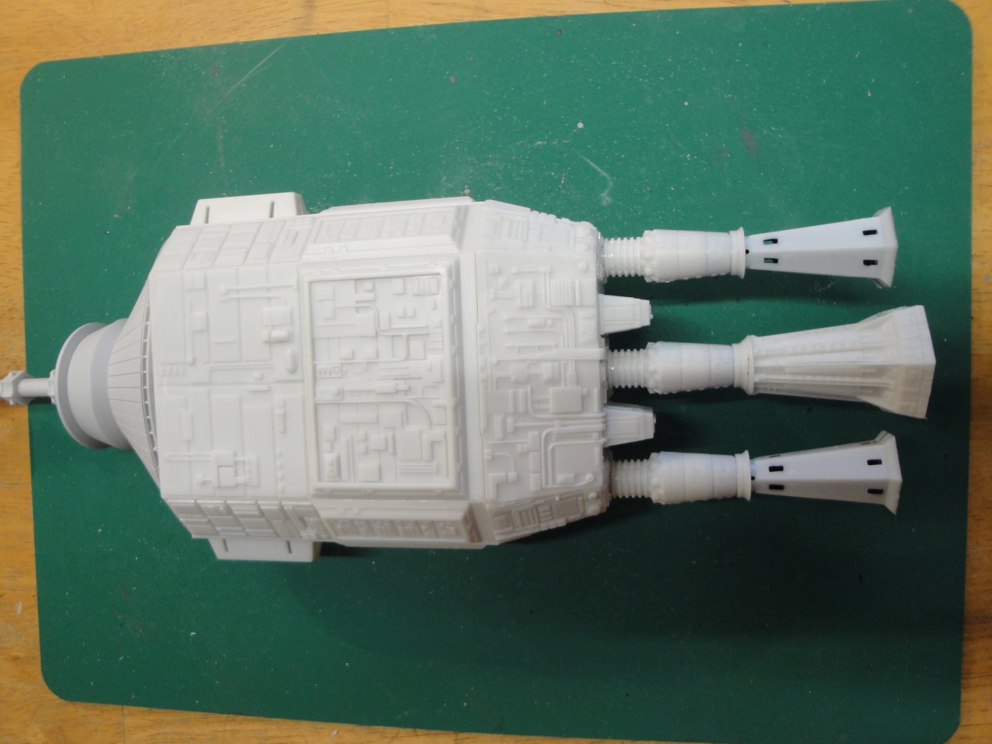
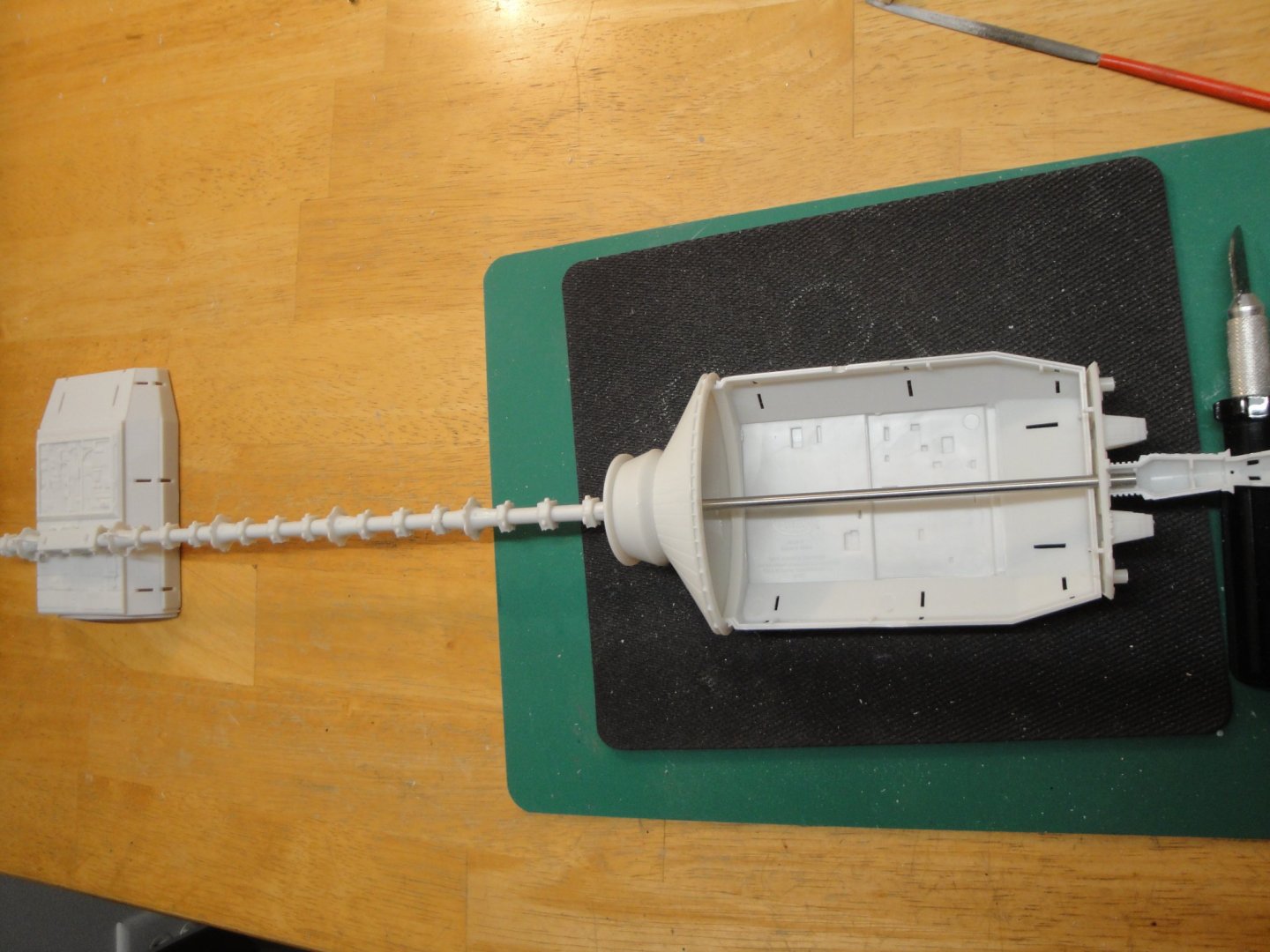
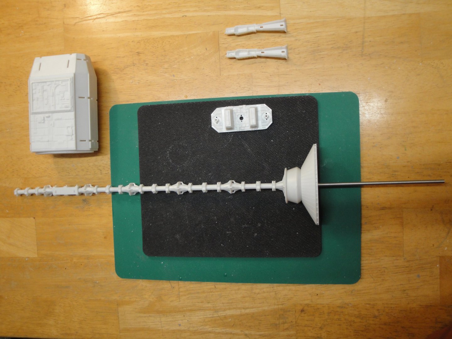
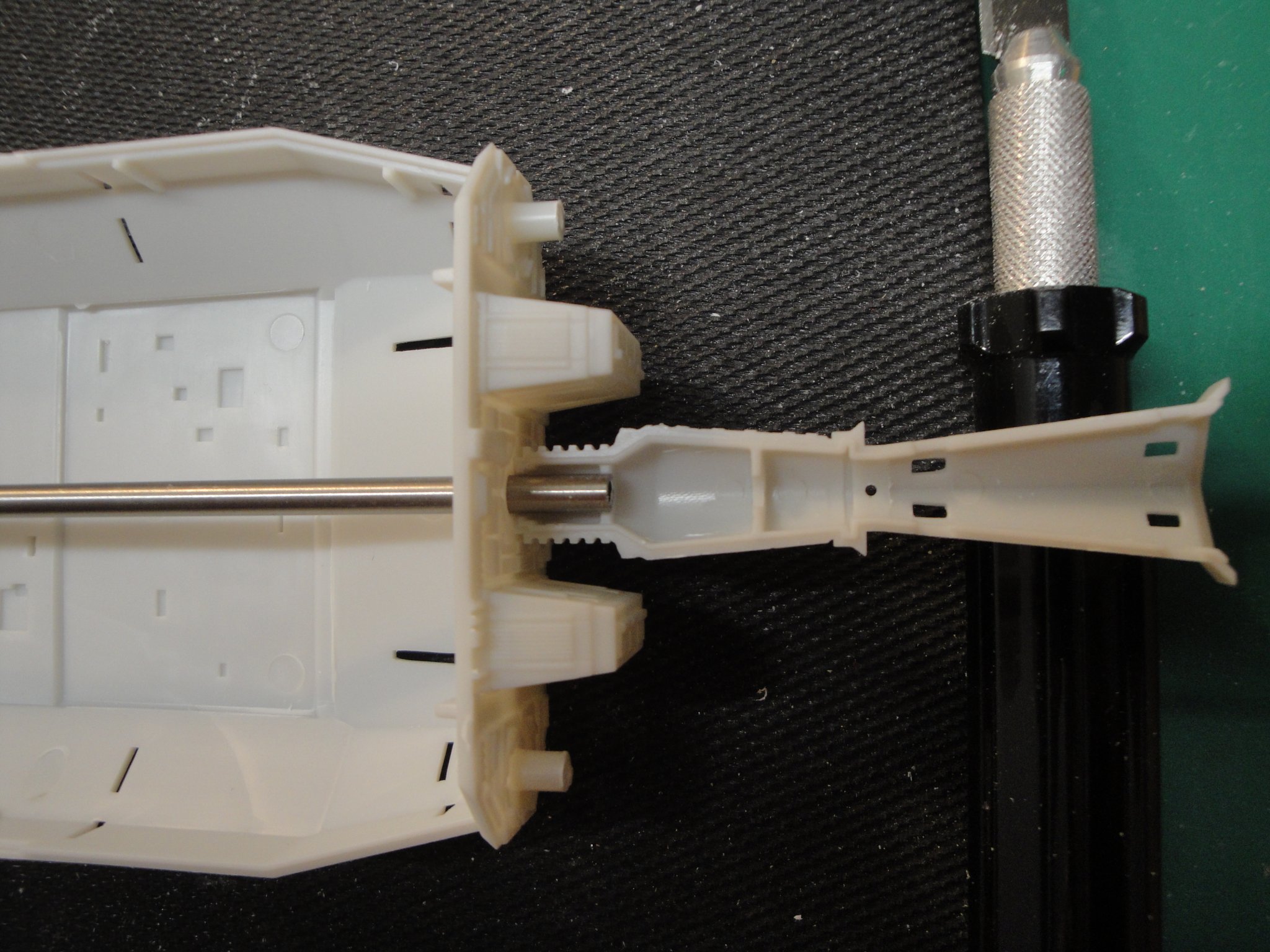
Moving "rearward", with the atomic engine thrusters and the rear spine:

The rear rod/tube needs to be cut off exactly 11 mm, to rest on the internal rib of the central thruster. inside that long spine, we will have to pass two wires for the various lights as will be explained later on. You could avoid cutting it and it will be alright. In my case, an LED and its wiring will be installed to the right of the tube, in that little cavity. This will simulate the reactors firing to propel the vessel during its long journey to Jupiter.
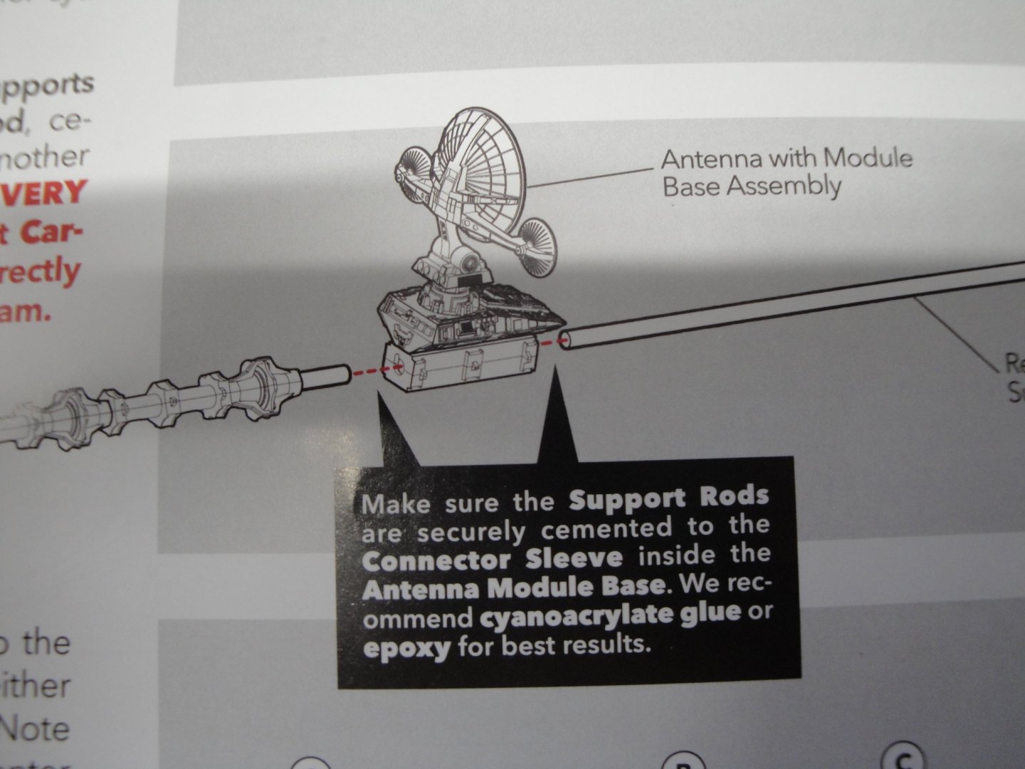
The picture below shows the antennae unit (left), the four rear bay holders and the atomic engines block (before gluing).
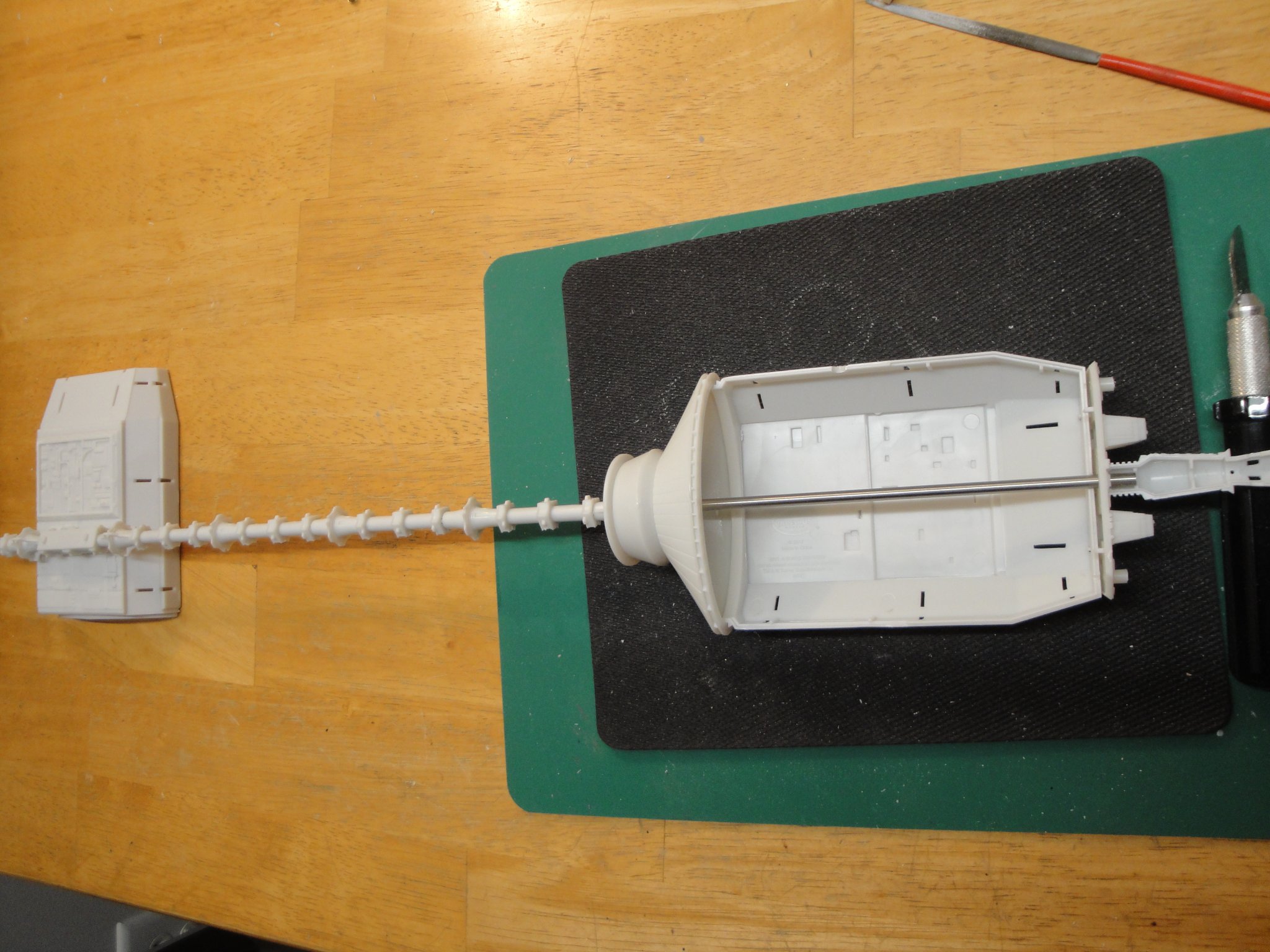
The rear tube is now glued to the antennae unit (coupler) with Cyanoacrylate glue. Don't put too much glue, be sure about what you do or use a slow curing glue. I had just enough time to push it to the mark on the rod, before the glue took over... It was a close call.
Below picture shows after gluing:
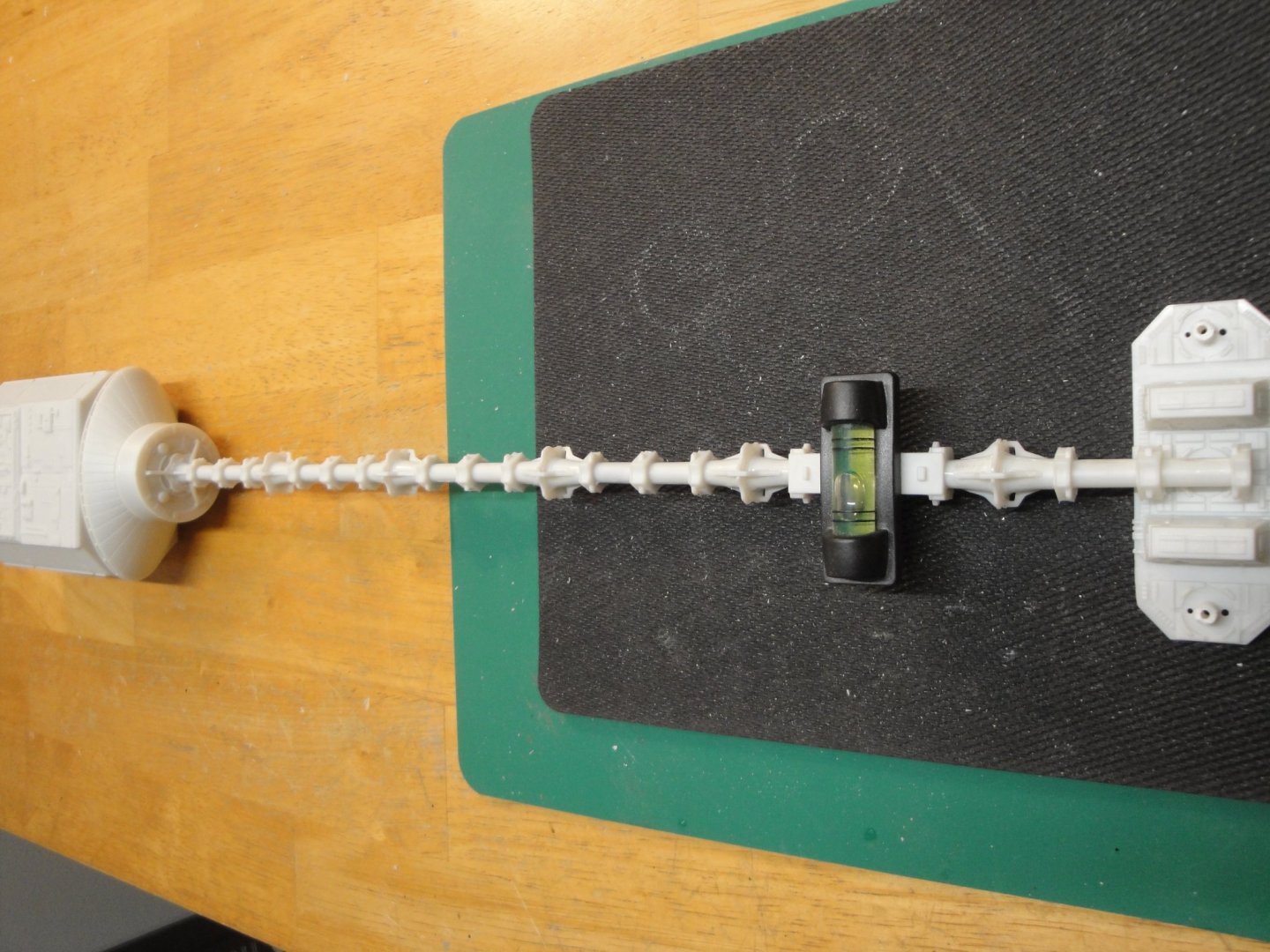
Perfect alignment must be obtained to have an antennae vertical with the engine block. I used a small bubble level as well as my eyes for making sure it is correctly aligned:
There is a tiny bit of rotational flexibility in the spine but not much actually. Finally, a coat of Vallejo primer is applied on the rear spine:
Yves
-
3 hours ago, VTHokiEE said:
Darn, I just started comparing the contents to another kit (on eBay) and it would seem that this kit is far from complete... if I can't find an inexpensive second kit for the missing pieces this build may not get off the ground.
Keep in mind that these kits never includes trucks and couplers. I have built a few of them, and they are not that easy, especially to render the metallic aspect of the car, with wooden parts.
Yves
- mtaylor, popeye the sailor, VTHokiEE and 1 other
-
4
-
2 hours ago, Katuna said:
Wait, I just realized this is still on MSW. Does a "space ship" constitute a ship? Curious minds want to know.
Katuna,
I thought about placing it in the Ship Model Kits section.... after all, it is a space Vessel, very comparable to a submarine. But then, I wanted to be a good citizen on this forum and not risk the wrath of the Forum police.
In the meantime, I count on you for picking up the pace on the Trumpeter Submarine build and keeping our audience entertained with underwater topics..... 😉
Yves
- Canute, popeye the sailor, hexnut and 3 others
-
6
-
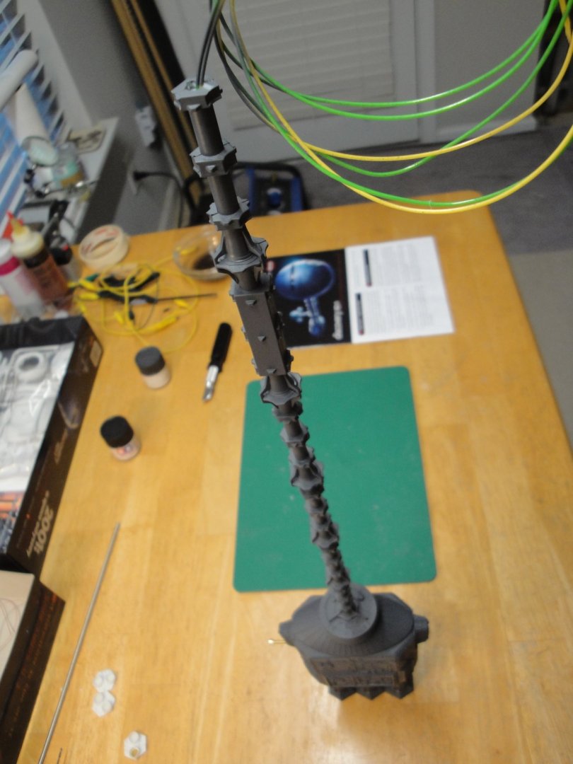
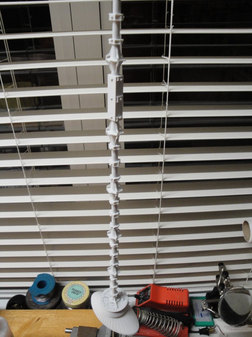
I have added still another aluminum tube around the brass tube. Over killing? probably, but now the rods are very secure and perfectly straight. I suspect that the main spine will not sag at all, when the vessel is supported on each end. Tubes are glued with epoxy two components glue:
And here is our spine assembly with the first two bay holders:
Yves
- CapnMac82, hexnut, GrandpaPhil and 5 others
-
8
-
14 minutes ago, Dubz said:
Good Choice. In my stash too (together with the EVA Pod and PE's) 🙂
Dirk
Thank you Dirk. HAPPY NEW YEAR and all my wishes for you to complete the Sherbourne and to get started on some new 2001 Plastic kits.
Yves
- mtaylor, popeye the sailor, Canute and 3 others
-
6
-
As I mentioned in the introduction of the Blog, I will be using the model as part of a celestial art piece. As such I will not be using the traditional way offered by Moebius, to display the kit. Moebius offers three stands under the living area (sphere), Earth antennae module and the propulsion block. The long model rests on these three rather flimsy stands to be displayed horizontally on a flat surface. My model is going to be "suspended" on the side and I wish to only have stands on the propulsion module and near the living quarters. In addition, I wish to provide some kind of illumination on the thrusters and on the main deck. Therefore, we have to rethink a little bit the kit and stiffen it considerably.
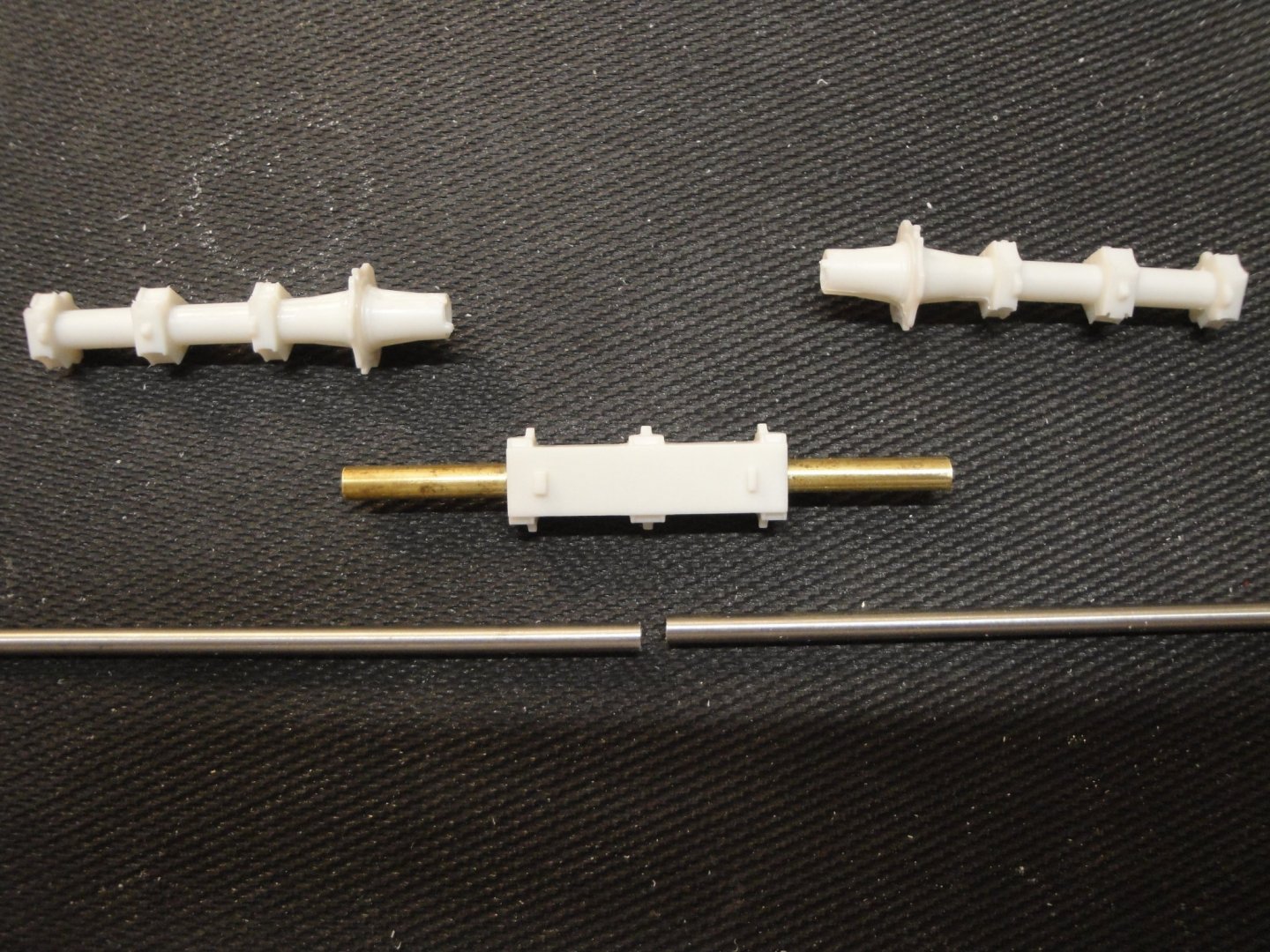
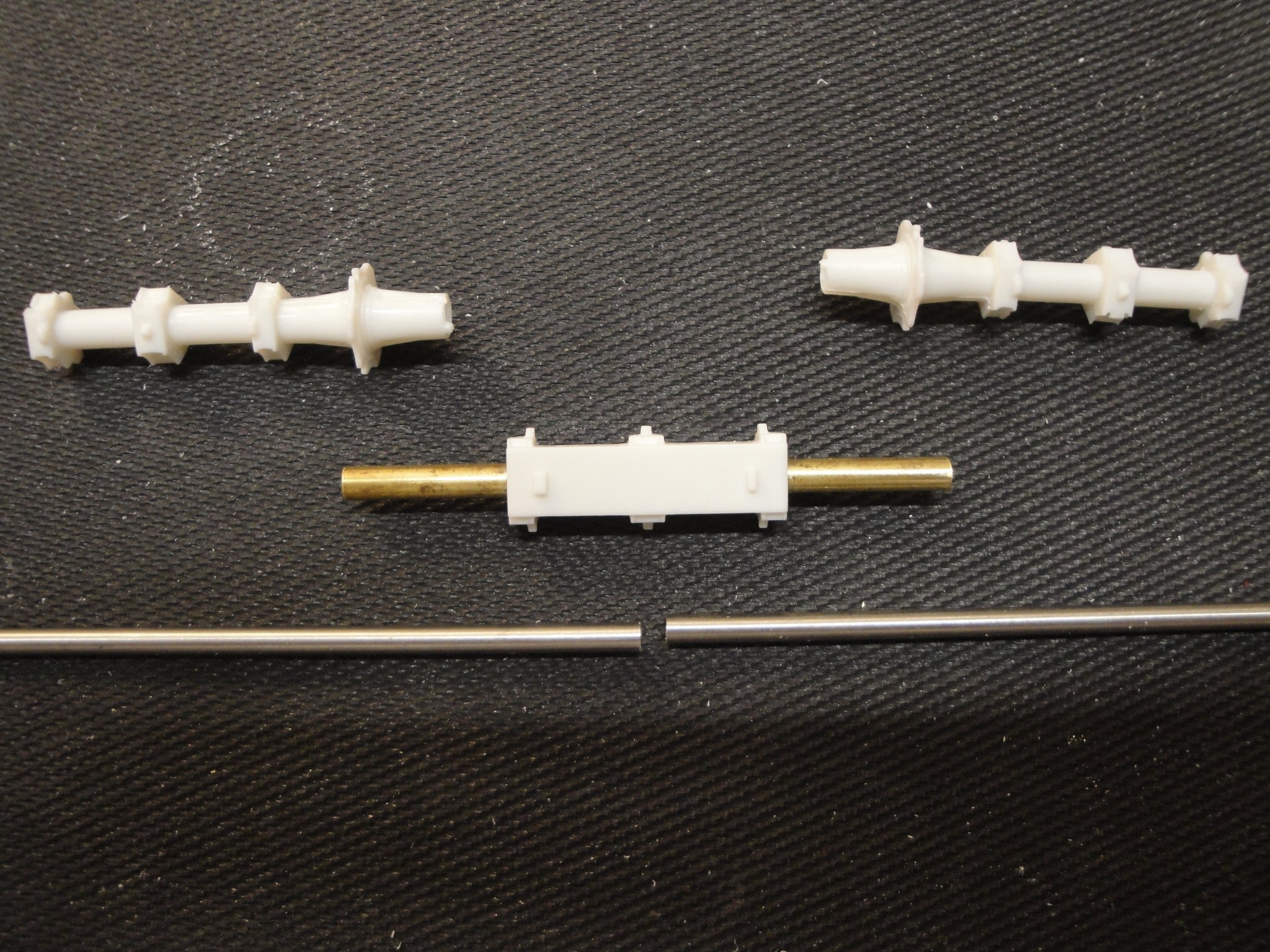
In the Moebius kit, the two spines (realized by two metallic tubes of 4 mm) are connected inside the Earth antennae module:
The piece of tube in charge of the coupling (as provided in the kit), is way too short and not tight enough. As a result, the two rods are sagging and not straight. It is okay if you go with the three stands approach of the kit. However, if you plan to have support only on both ends of the vessel, the spine will sag and look more like an arch. So, we need to stiffen it up.
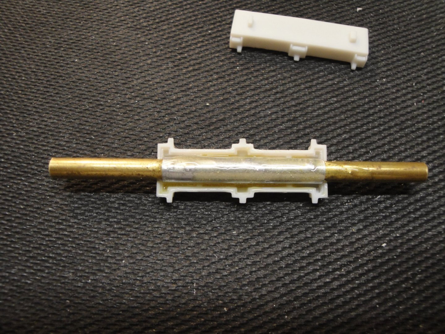
The following picture shows what I have in mind:

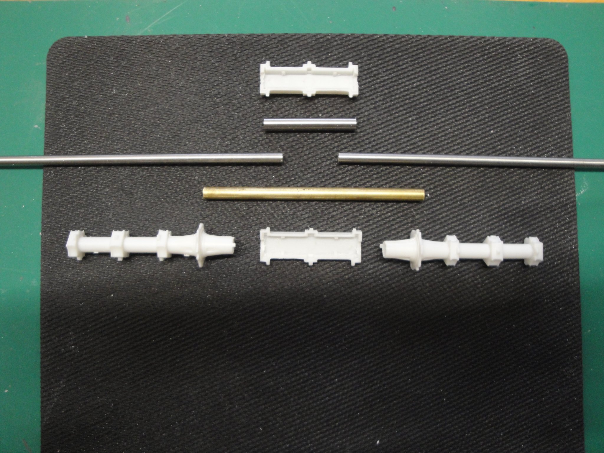
The top piece of tube is what Moebius provides in the kit. Then we have the two rods of 4 mm each. The brass tube I decided to use offers an additional inch of support on both sides and fits very tightly on the 4 mm rods. When lining up everything, the spine is straight and sturdy. The brass tube is #129 3/16 x 0.014 made by K&S Engineering and can be found in almost all Hobby Shops.
The two adjacent modules have to be gently enlarged to accommodate the extra diameter of the brass tube. This is done first with a bit of 4.5 mm and then fine-tuned with a round file (I do not have a 4.8 mm bit which would have been perfect. The coupling is very tight and will hopefully provide us with a "straight" vessel.
Yves
- Dubz, lmagna, thibaultron and 6 others
-
9
-
Folks,
I have narrowed my decision to the following build, for the time being:
Thank you all for the many "likes" and wonderful support, all along the building of that massive and complex submarine.
Yves
- Landrotten Highlander, CDW, lmagna and 6 others
-
9


Moebius 2001 XD-1 DISCOVERY - Polystyrene - 1/144 - Yves Vidal - Finished
in Non-ship/categorised builds
Posted · Edited by yvesvidal
I just finished the 20 some Pods that are attached on the rear spine. Now, some paint, a white wash and that part of the vessel should be finished.
Yves