yvesvidal
-
Posts
3,624 -
Joined
-
Last visited
Content Type
Profiles
Forums
Gallery
Events
Everything posted by yvesvidal
-
 Yes, you can keep your feet warm, by placing them on the dog, sleeping underneath. Good plan!!! Yves
 -
Beautiful model. Now, you need to get another one.... Yves
-
I wish the construction of the galleries was as simple as you describe, on the CAF Model kits..... 😞 Yves
- 488 replies
-
- 5
-

-
- Indefatigable
- Vanguard Models
- (and 1 more)
-
Cool kit !! I have it on my wish list with Squadron and will be following your build log with curiosity. Yves
-
A block of wood for the lifeboat....? They must be kidding !! I like your alternative much better. Yves
-
Thank you Alan, for all the details and explanations. You are doing a very fine job and I cannot wait to see the Corvette under her new case. Yves
- 460 replies
-
- 7
-
-

-
- Finished
- Flower-class
- (and 1 more)
-
Are you going to build a diorama, with water ? Yves
- 200 replies
-
- 3
-
-
- Transport No. 103
- Hasegawa
- (and 4 more)
-
Alan, Could you be more specific with the following: - What company did you use for the case? Was it Acrylic Job ? - What kind of glue was used to glue the panels? (You did a great job, by the way, on that difficult task). - What was the price of the case? Perhaps you can install some small handles on each side of the case, to help you lift it and place it in position. I am very interested since we have the same ship..... 🙂 Yves
- 460 replies
-
- 7
-
-
- Finished
- Flower-class
- (and 1 more)
-
1/200 Trumpeter IJN YAMATO - issued by MRC/Gallery Models
yvesvidal replied to yvesvidal's topic in REVIEWS: Model kits
Go for it Craig: it will be a master piece, done by you . Yves- 104 replies
-
- 4
-
-
- MRC/Gallery
- Yamato
- (and 1 more)
-
Once you tire of the HMSH Britannic, you need to resurrect your Enterprise, Kevin. Yves
-
Nobody will want to build the quarter deck and hide this beautiful cabin from the view. Maybe Chris will design a removable deck to show the interior.... Yves
- 488 replies
-
- 10
-
-
- Indefatigable
- Vanguard Models
- (and 1 more)
-
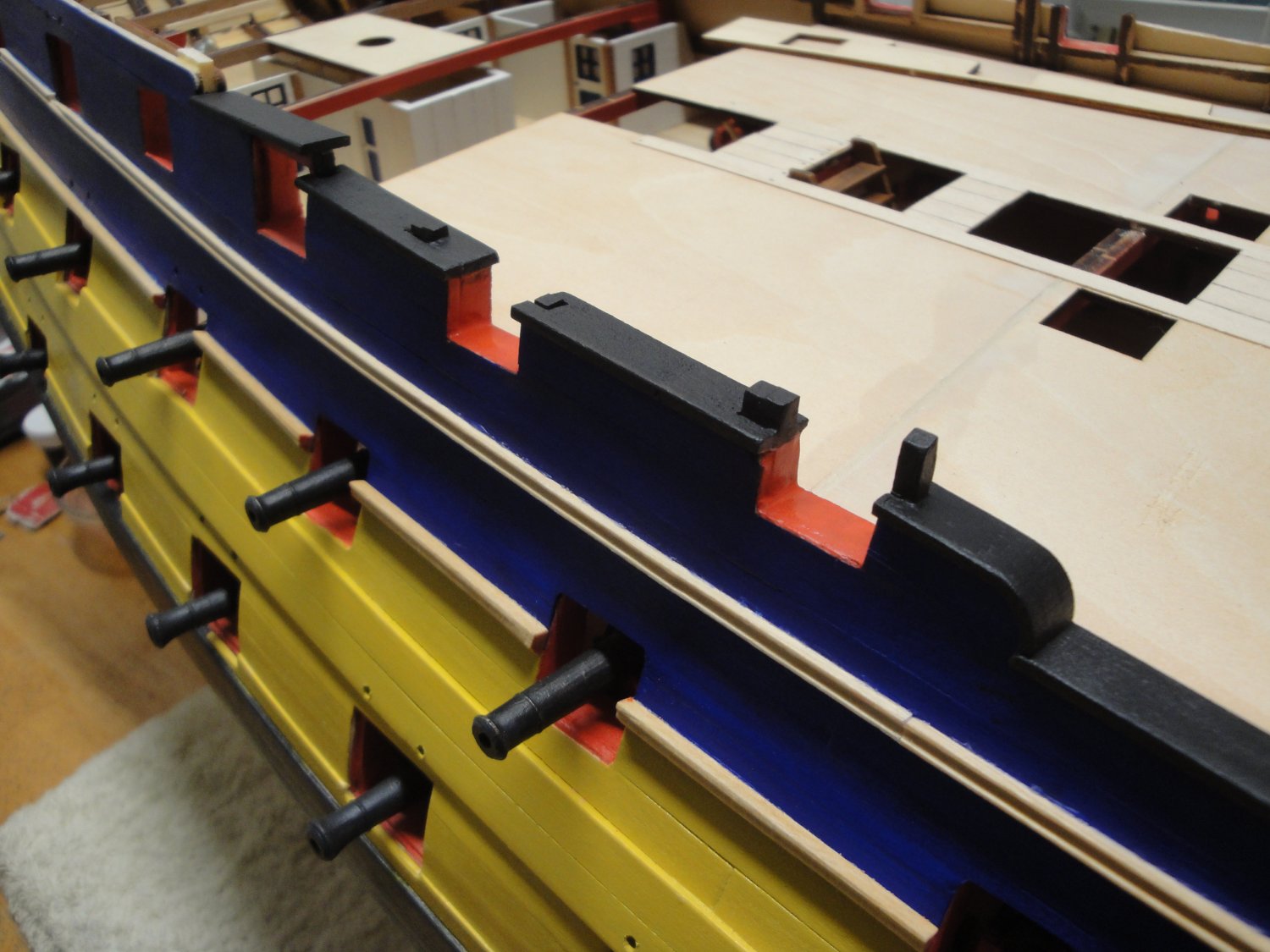
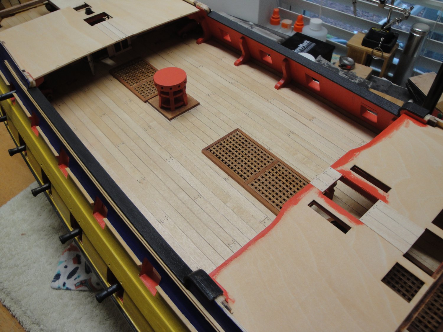
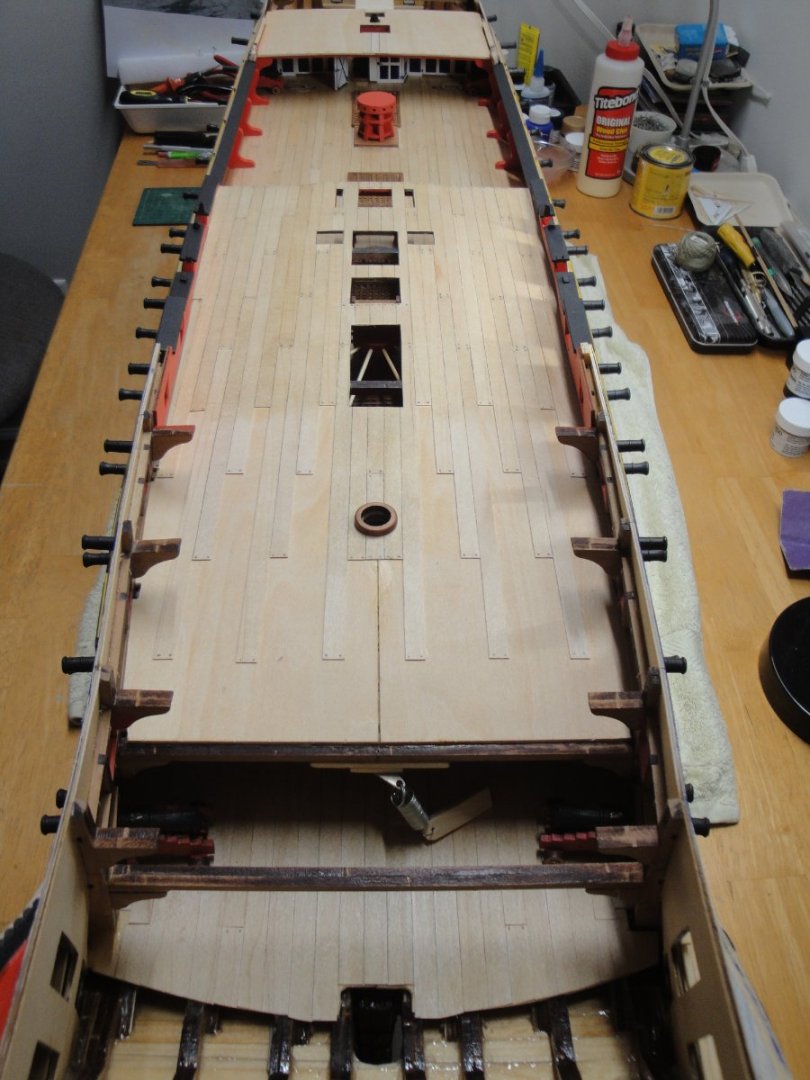
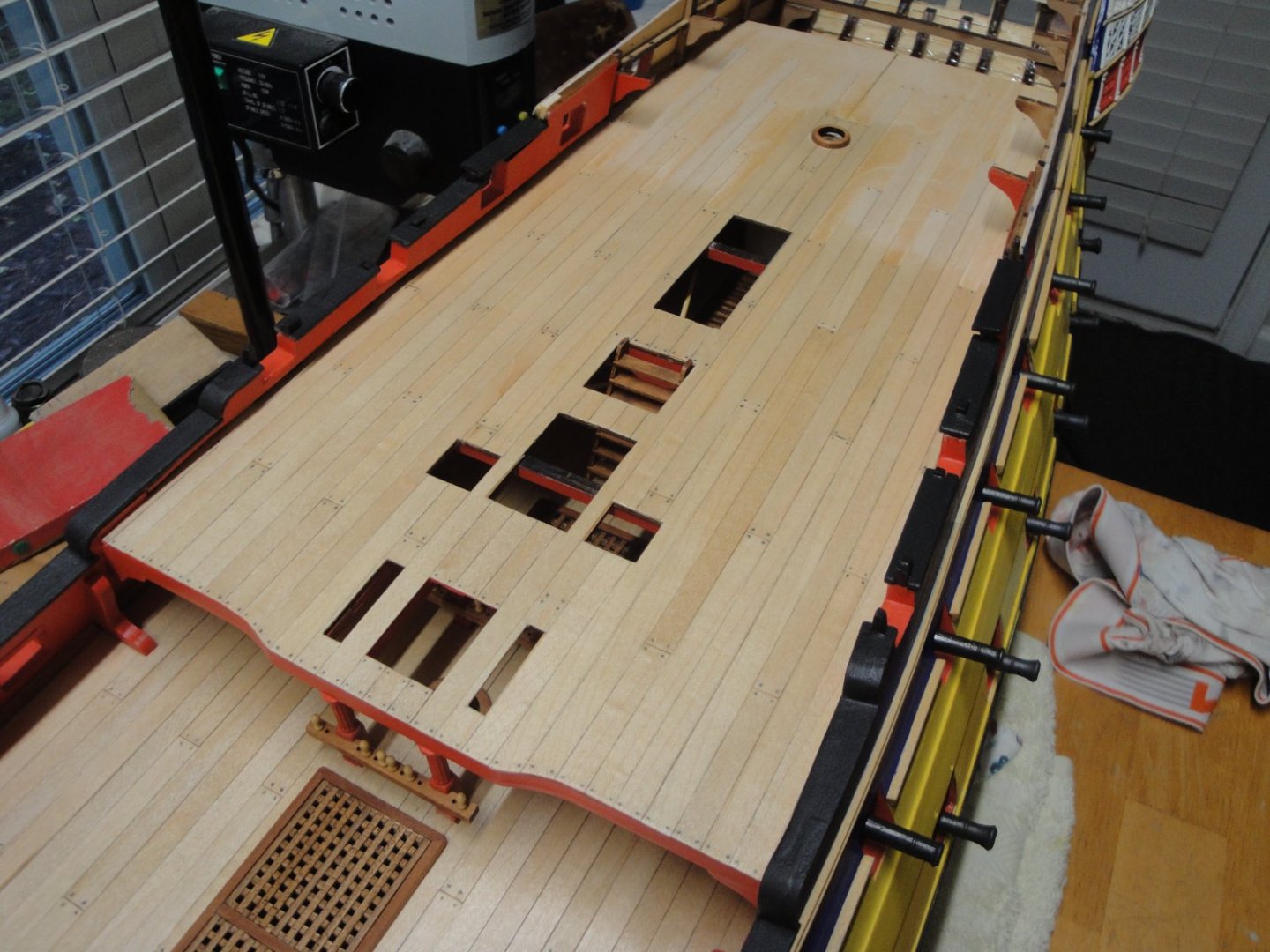
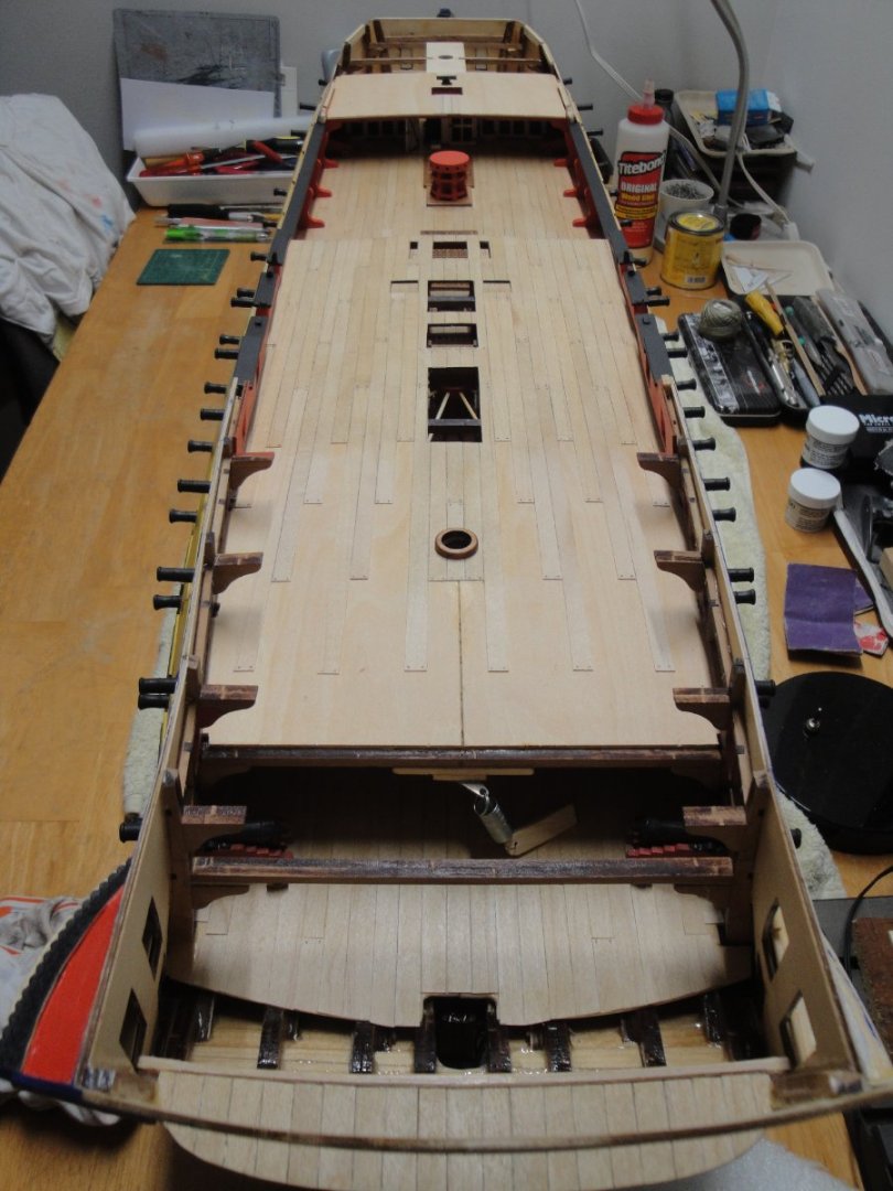
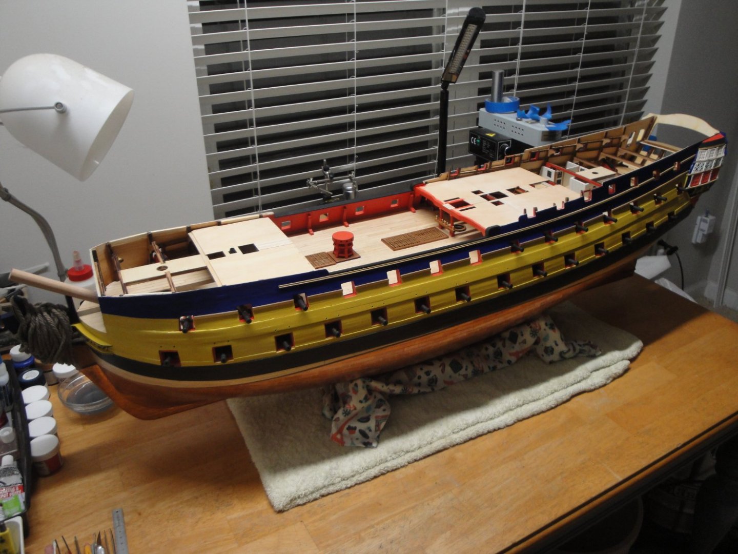
It is now time to work on the rear quarterdeck. Below is the last picture of that part of the ship, never to be seen again: As usual, I am gluing each side separately: Planking can be started for the starboard side of the ship: The floor is treated with Wipe On Poly and you can see the demarcation where the wood has not yet been treated. The kit offers some bulwarks, unfortunately too short, leaving an impressive gap between the floor and the bulwark. I am thinking to remedy to that error with a strip of wood carved as a water channel: That strip of wood is 4 mm high/thick and will fill that enormous gap. The other side is glued and the planking is completed: Et voila, where we stand: Yves


- 507 replies
-
- 25
-
-

-
That is gorgeous !!! I wish my Bellona had such details...... :-( Yves
- 488 replies
-
- 5
-
-
- Indefatigable
- Vanguard Models
- (and 1 more)
-
1/200 Trumpeter IJN YAMATO - issued by MRC/Gallery Models
yvesvidal replied to yvesvidal's topic in REVIEWS: Model kits
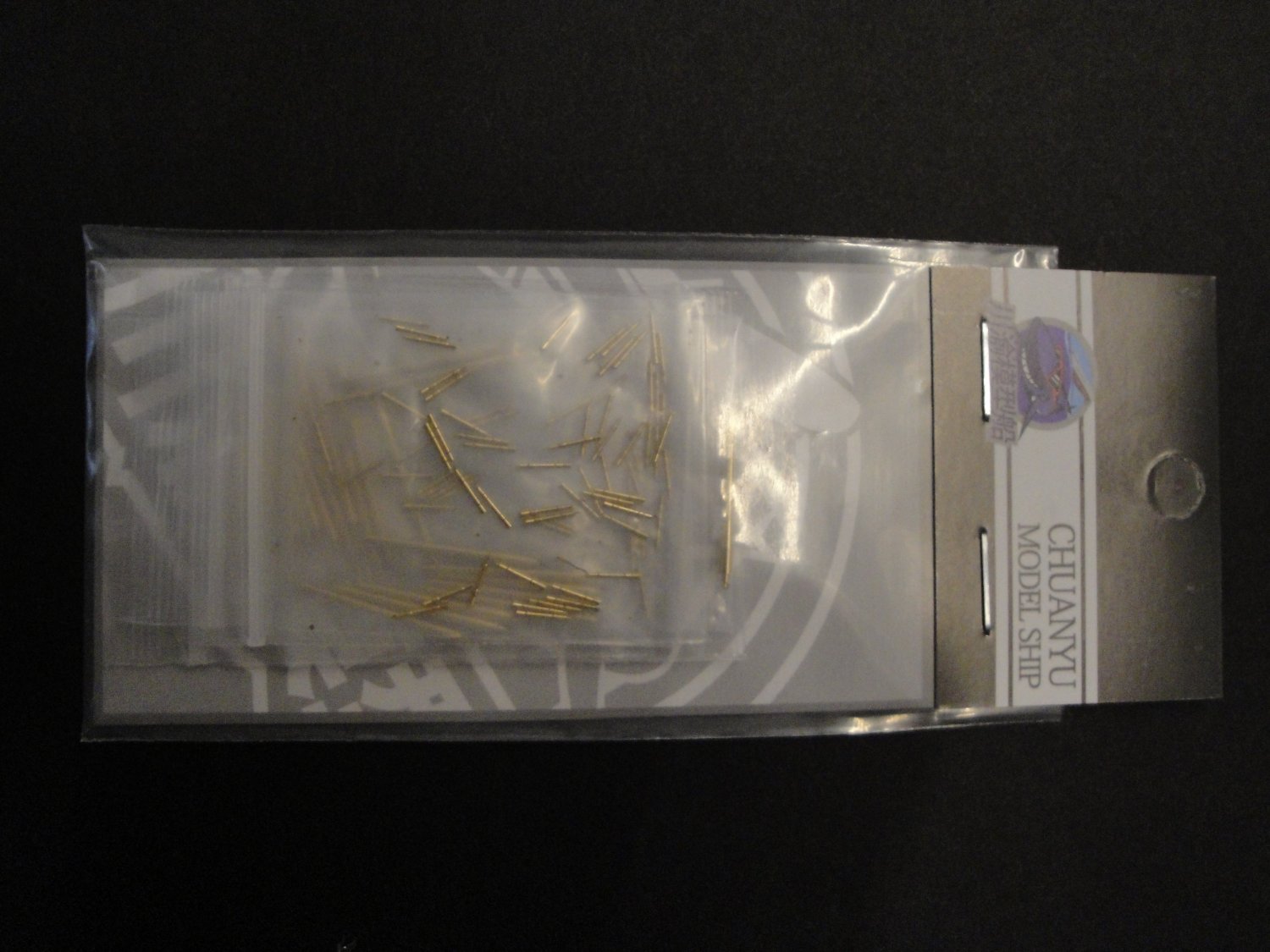
I just received a supplement kit with the wooden decks, metal guns, chains and masks for the deck. This was purchased on E-Bay. There are no instructions but hopefully, once you get the QDDR code on your phone, something should happen..... The overall kit was about $100.00. I just wish they printed a sheet of instructions.... Yves

- 104 replies
-
- 7
-
-
- MRC/Gallery
- Yamato
- (and 1 more)
-
I am with you: TAMIYA paints are fabulous and very easy to spray. Just use 50-60% paint and 50-40% thinner and you are good to go. Vallejo? I just cannot do anything good with them. Their primer is okay on plastic but a disaster on brass parts (Photo Etched). I wish TAMIYA would have more colors.... especially for ships. Yves
-
What a fantastic collection !!! I will be following your new Build Log. It looks very promising. Yves
- 113 replies
-
- 5
-
-
- Cairo
- BlueJacket Shipcrafters
- (and 1 more)
-
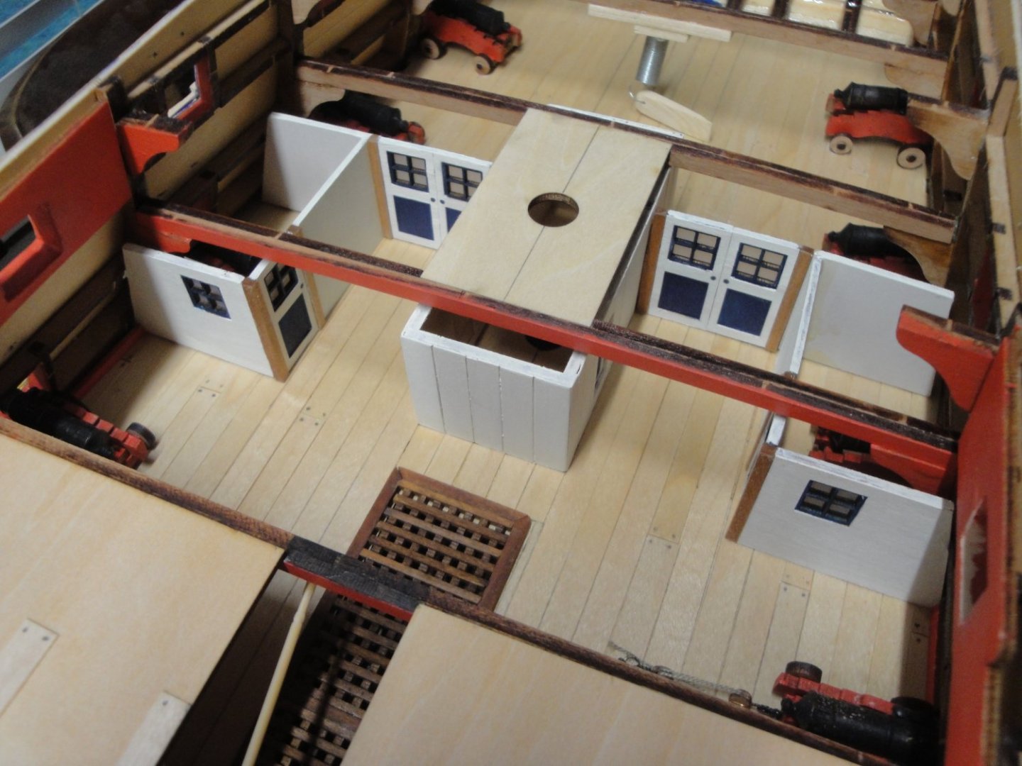
Aon, I did indeed receive an answer from Chris W. Yes, the ladder would have been folded or moved to another location. I wanted to keep the capstan (almost) fully deployed and retain the ladder in its regular position. I think I have achieved that and it really does not matter because nothing shows. Yves
-
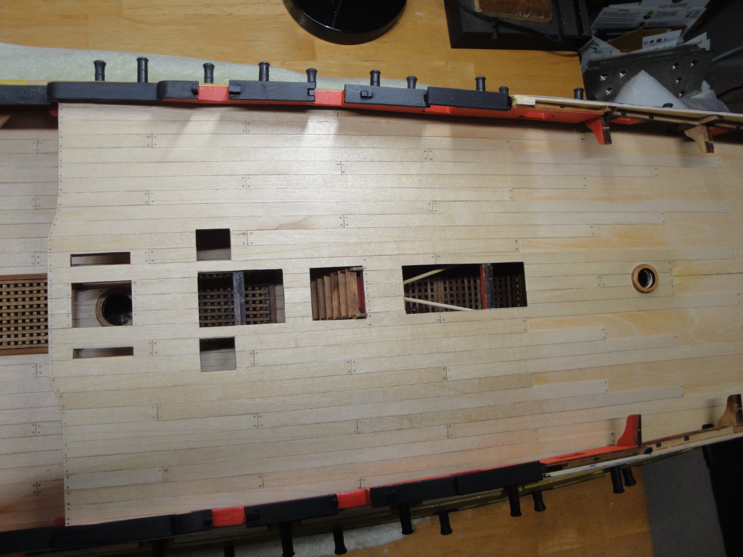
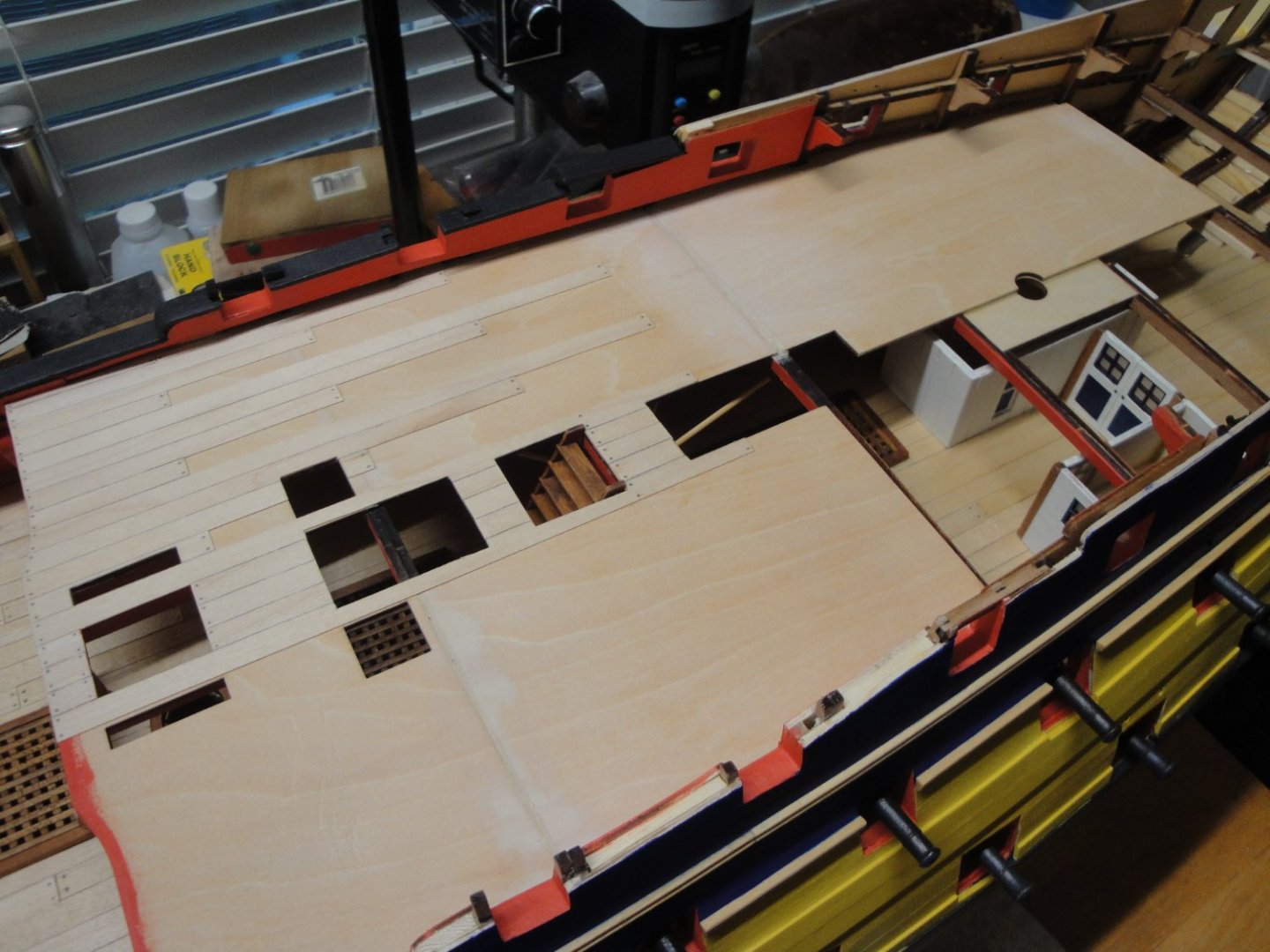
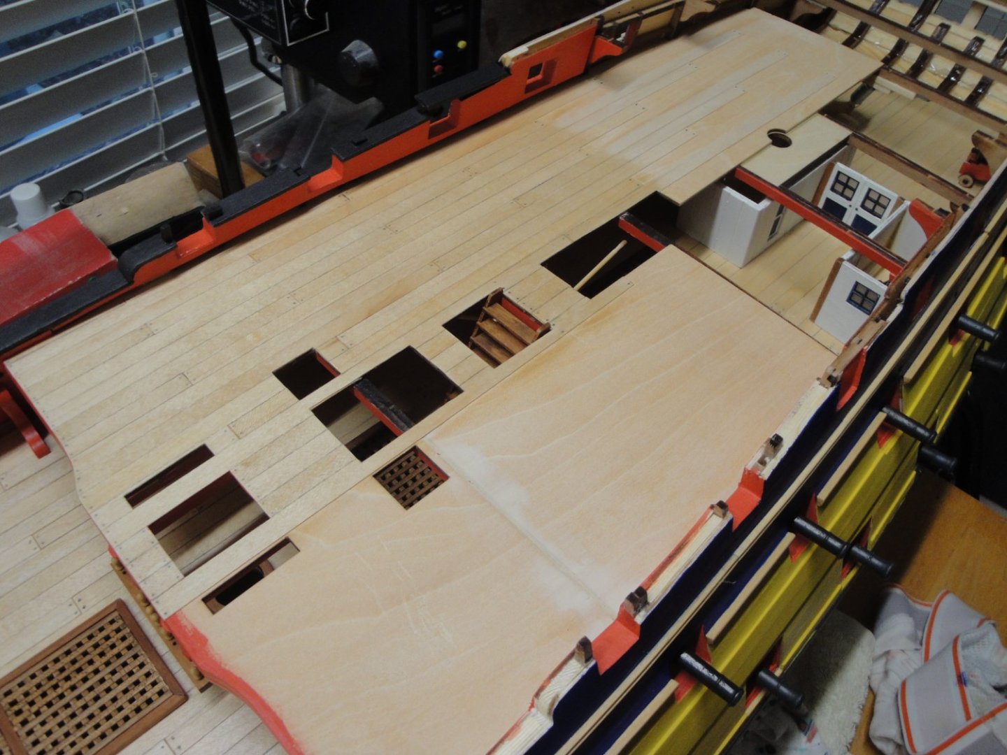
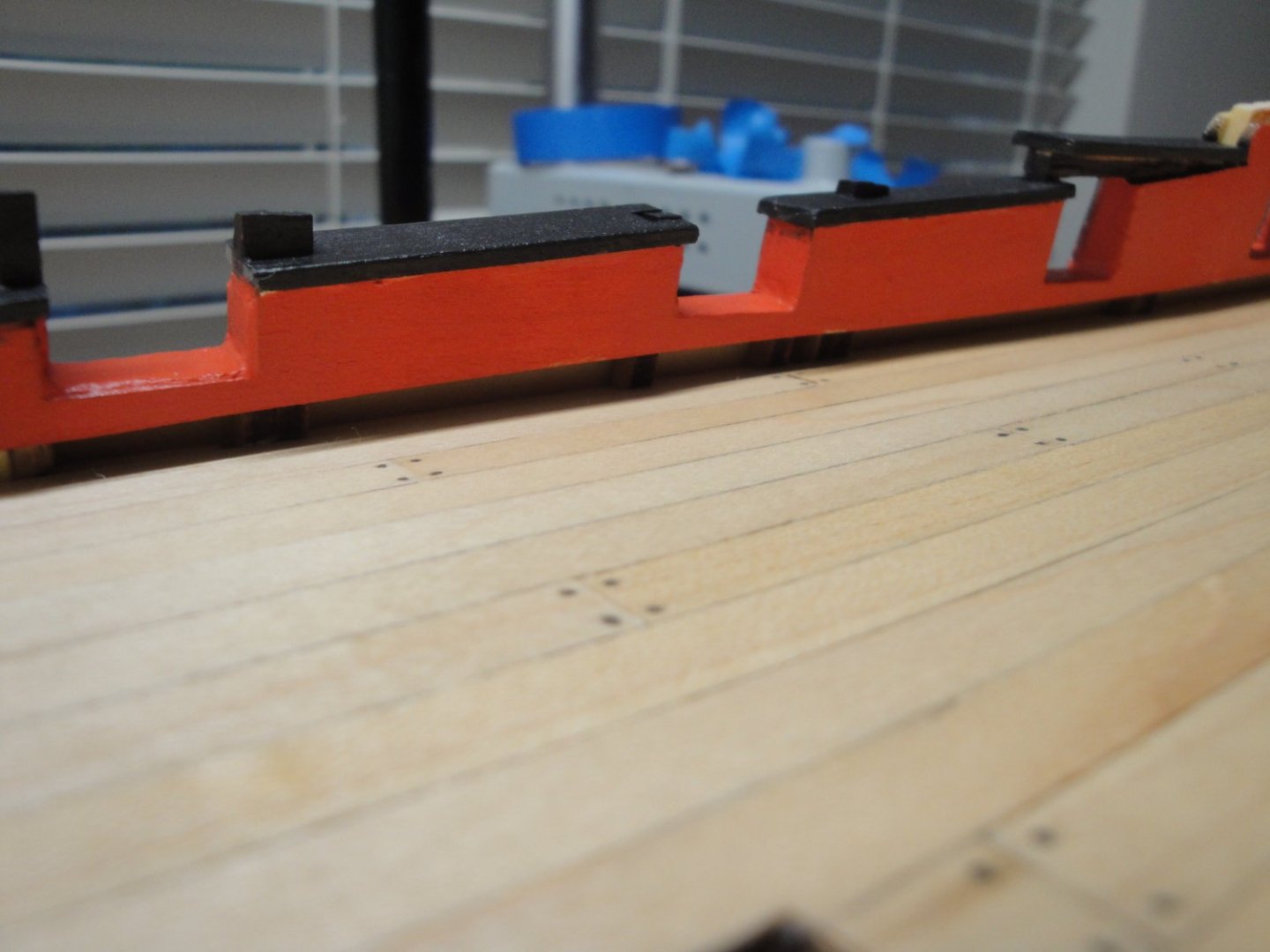
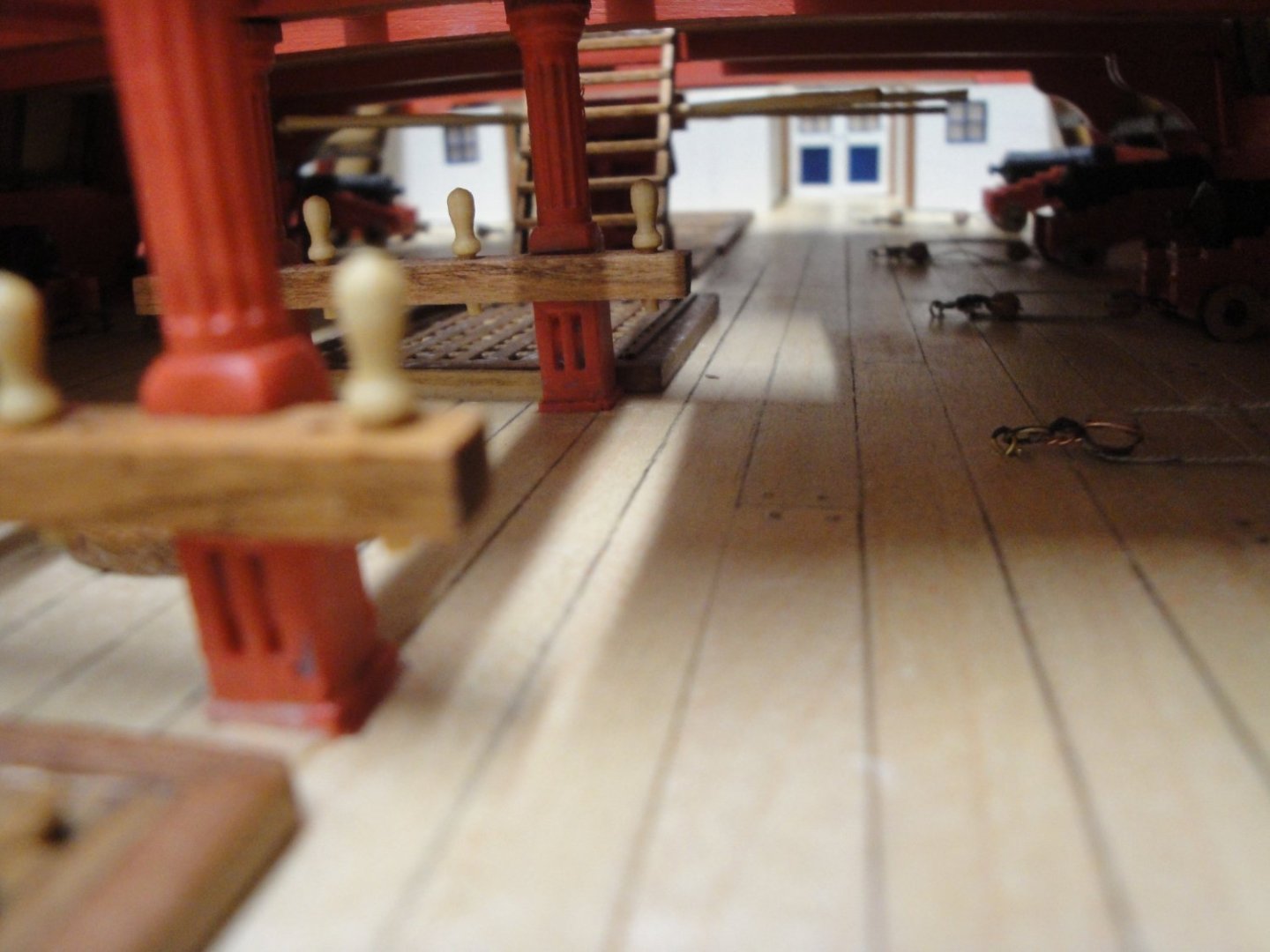
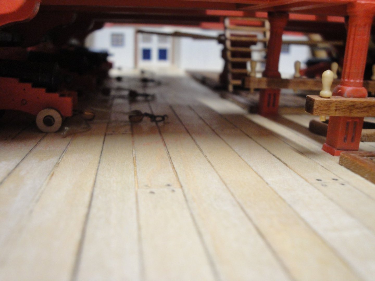
I am now working on the railings in the mid-section of the ship: The space inside the bulwarks is filled with pieces of wood for the hull planking. They fit perfectly and are glued with Titebond for additional strength and stiffness: After a nice sanding, the top rails can be installed: Et voila... Yves


- 507 replies
-
- 17
-
-
-
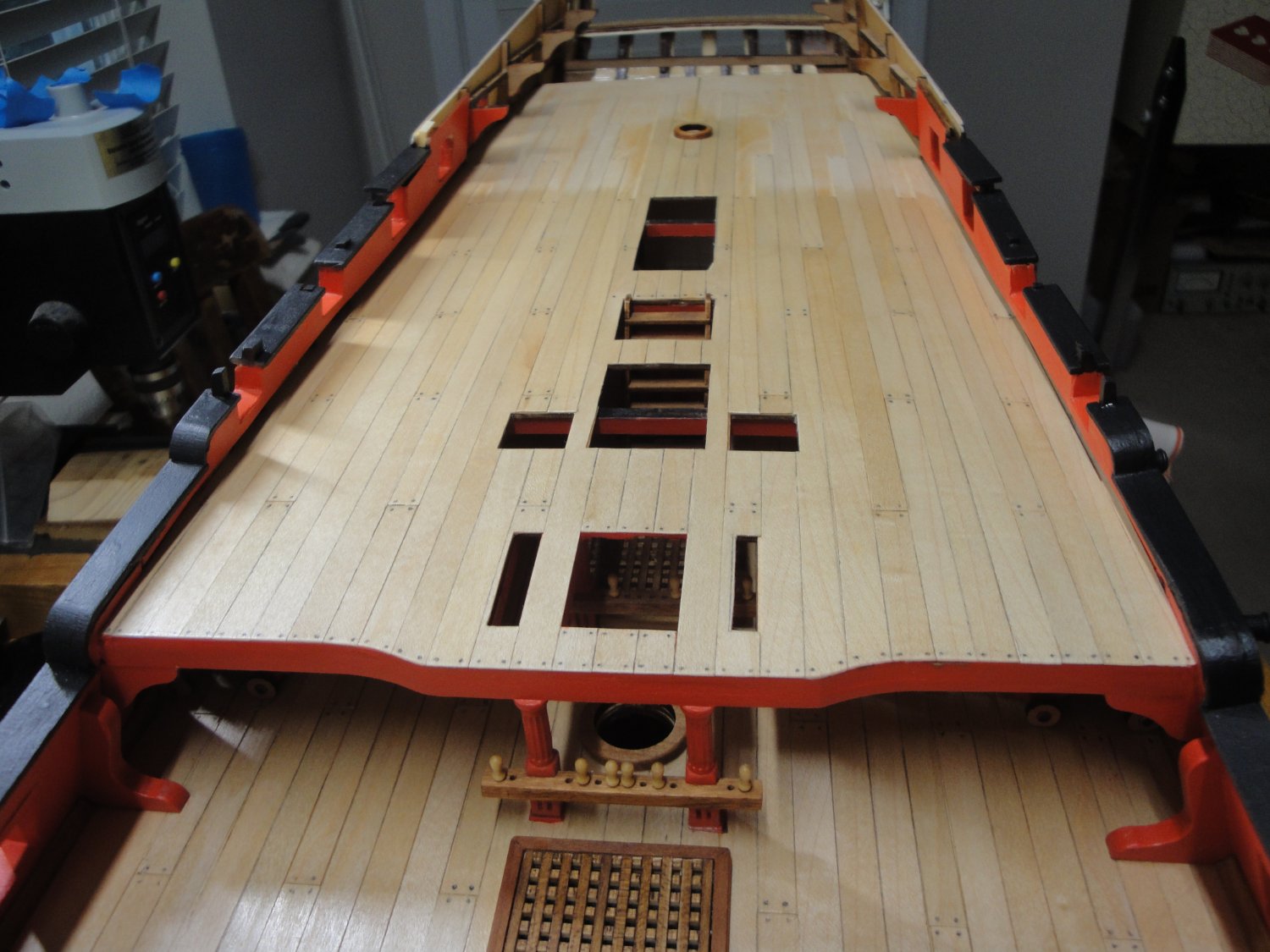
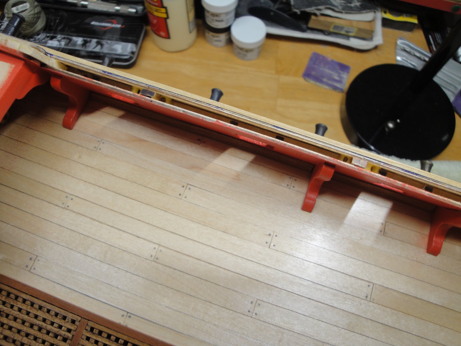
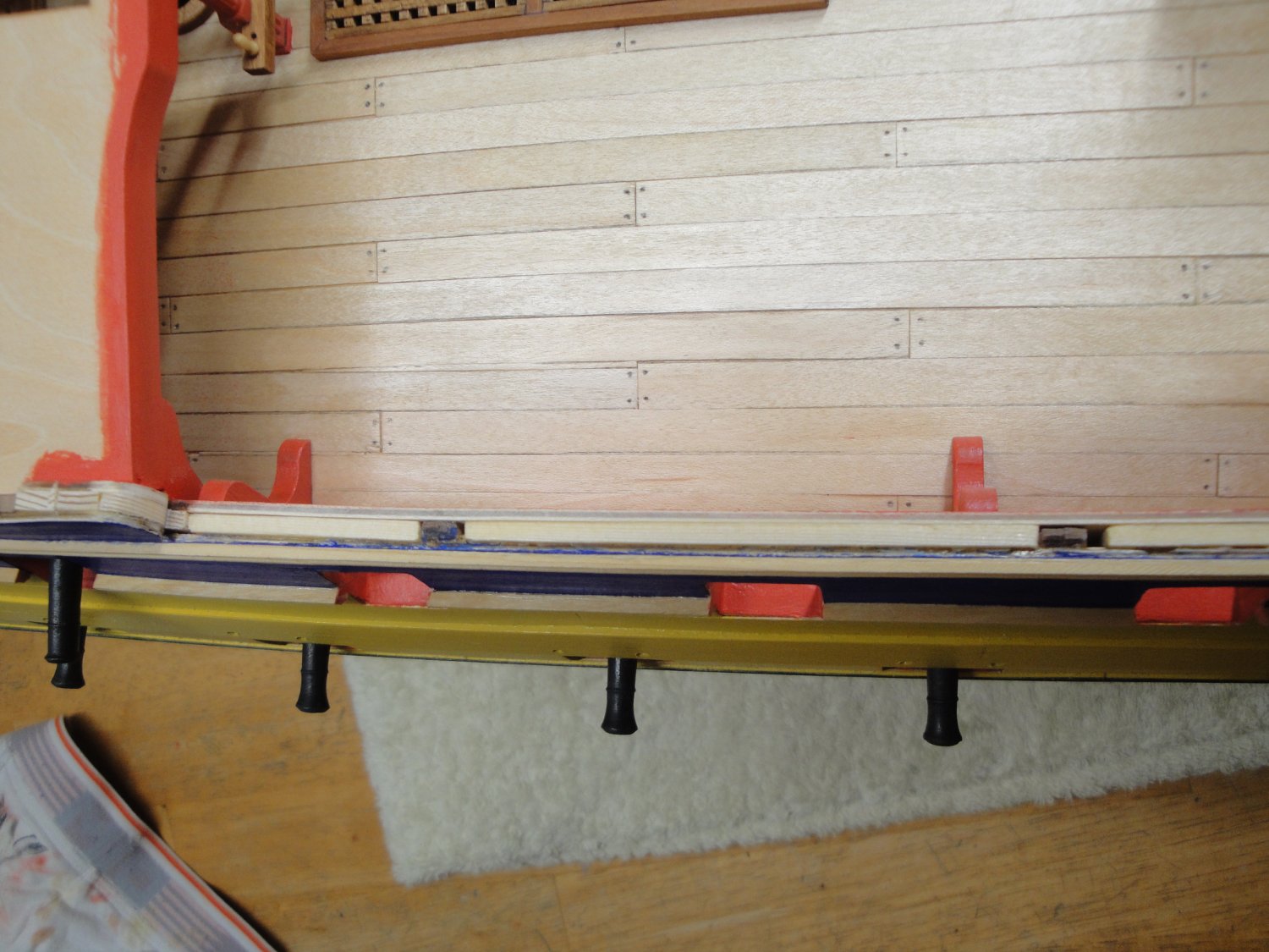
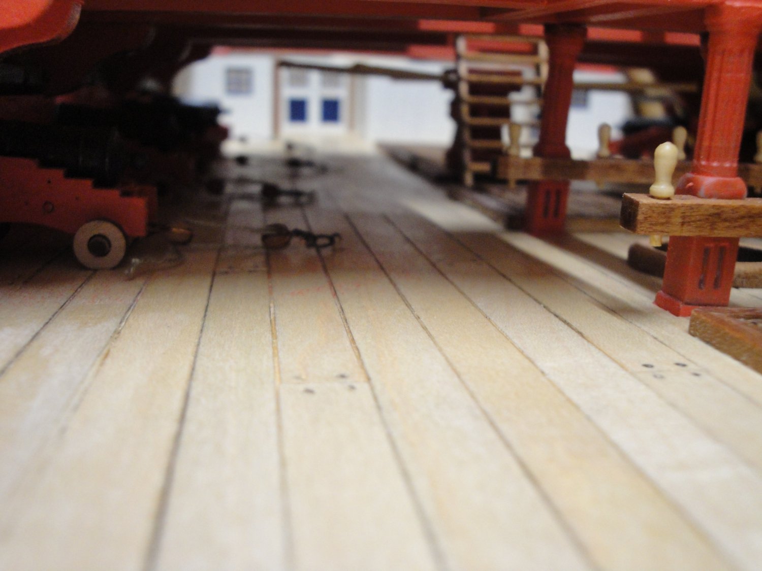
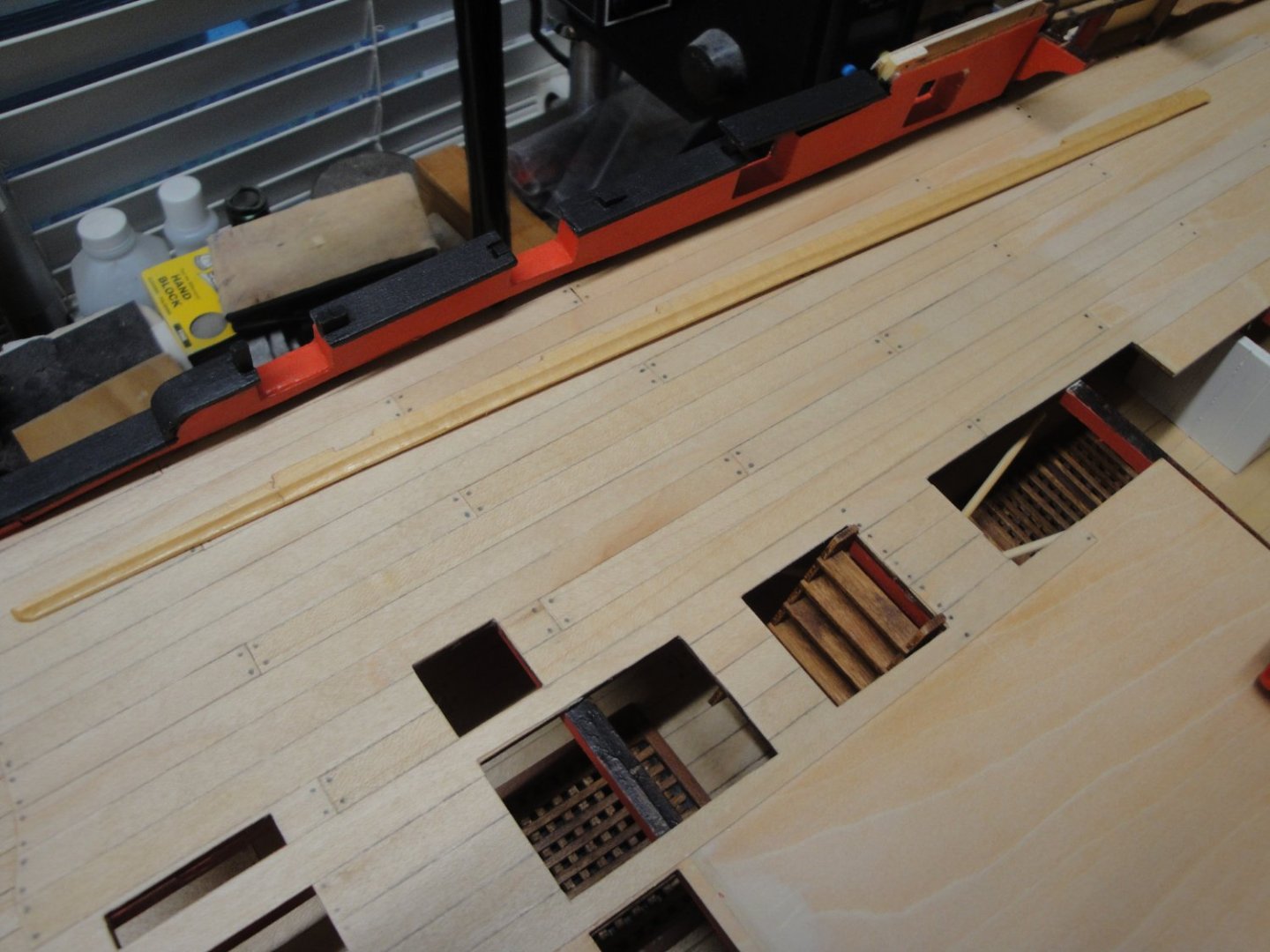
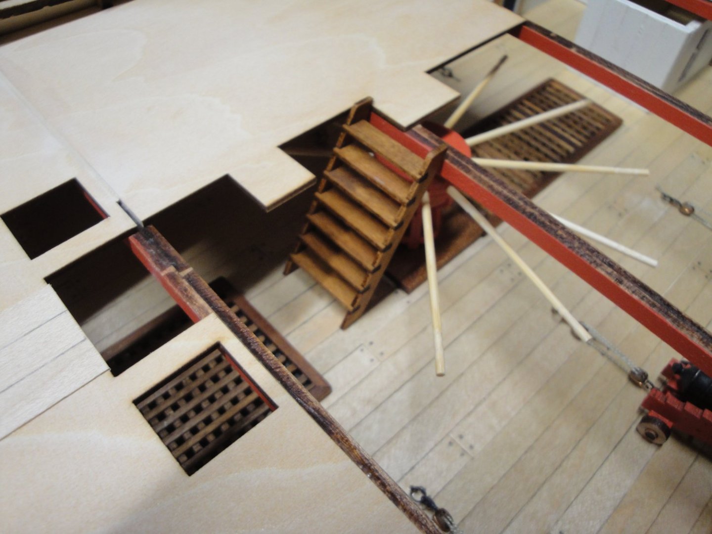
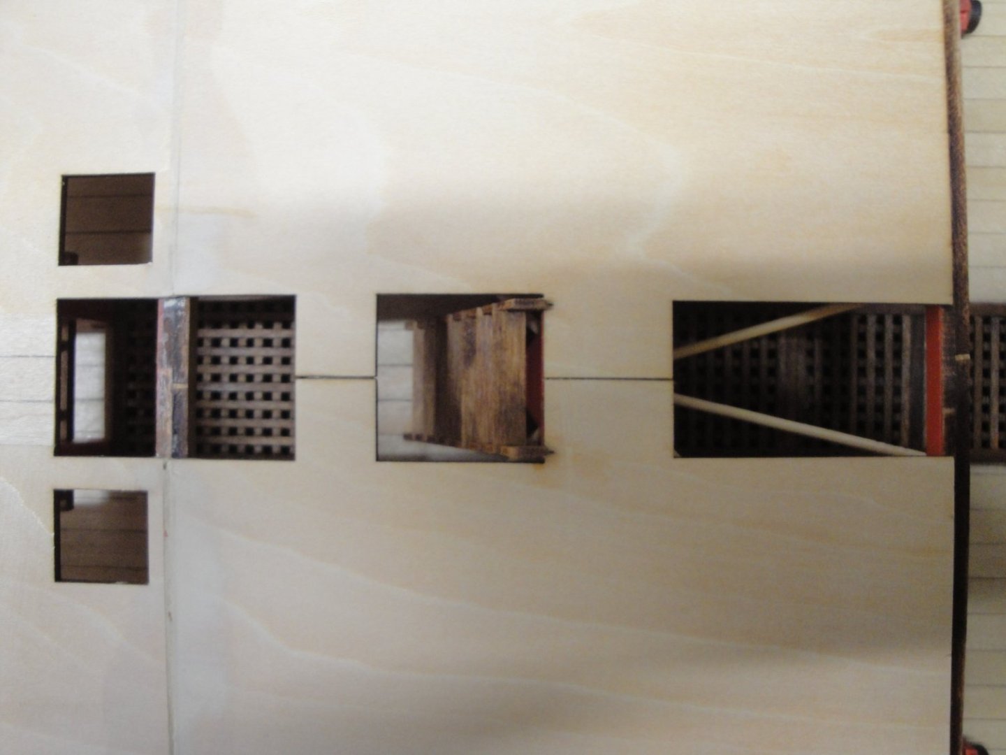
Then, we have this issue that we discussed a few posts ago: the conflict between the main ladder and the rear capstan !! I finally found a way around it, by simply cutting two spikes of the main capstan to free up some space for the ladder: That fits and it still retains that working (no longer now...) capstan. I recommend gluing the ladder before closing the second half of the sub-floor. All this precious and delicate work is now fully covered. It is one of the drawbacks on these large ships with their multi decks, hiding all the equipment underneath. A few pictures of what should remain unseen..... :-( Yves

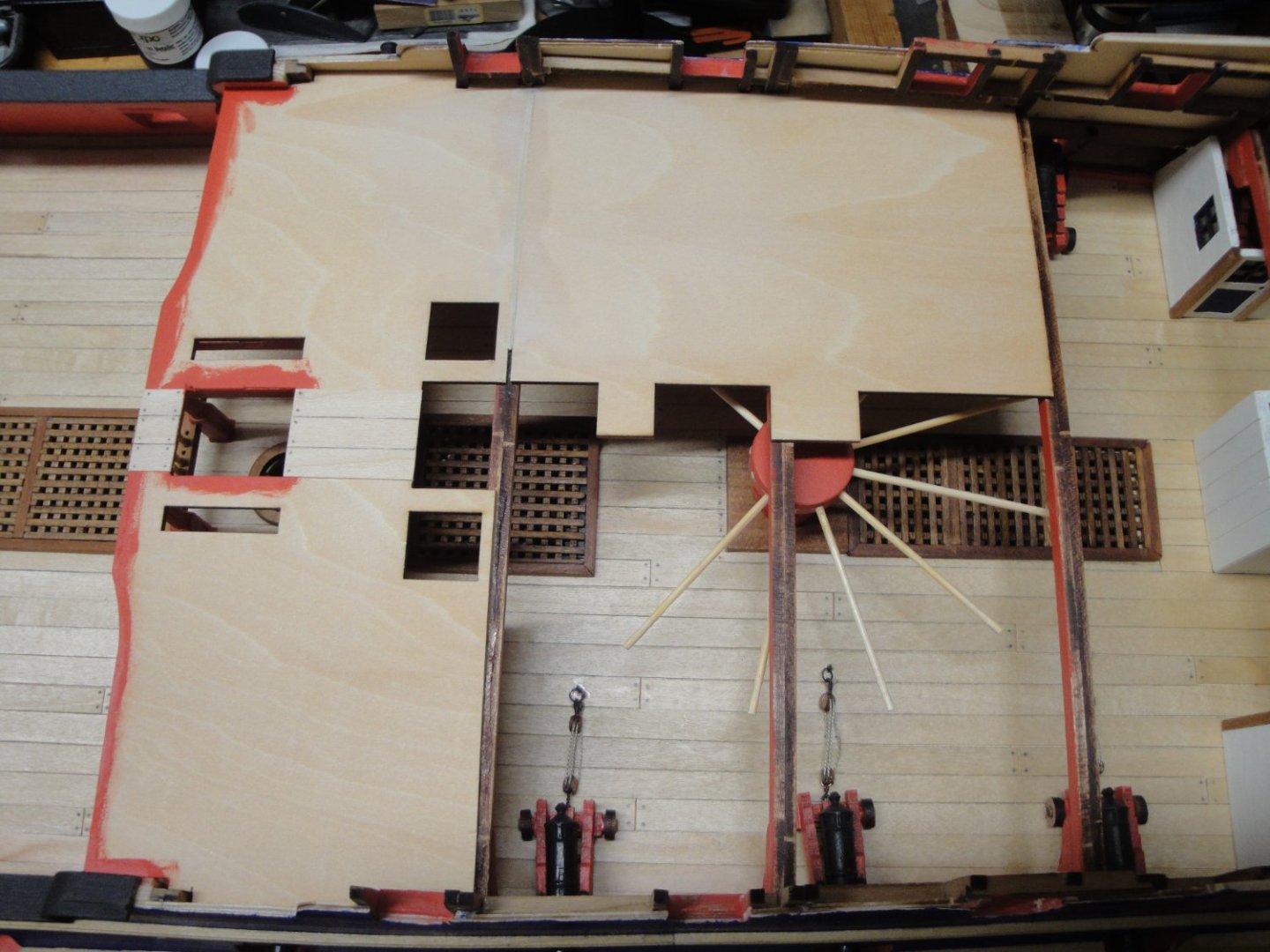
-
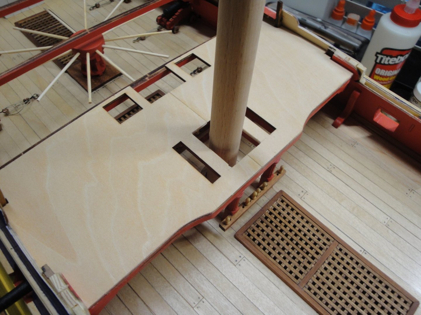
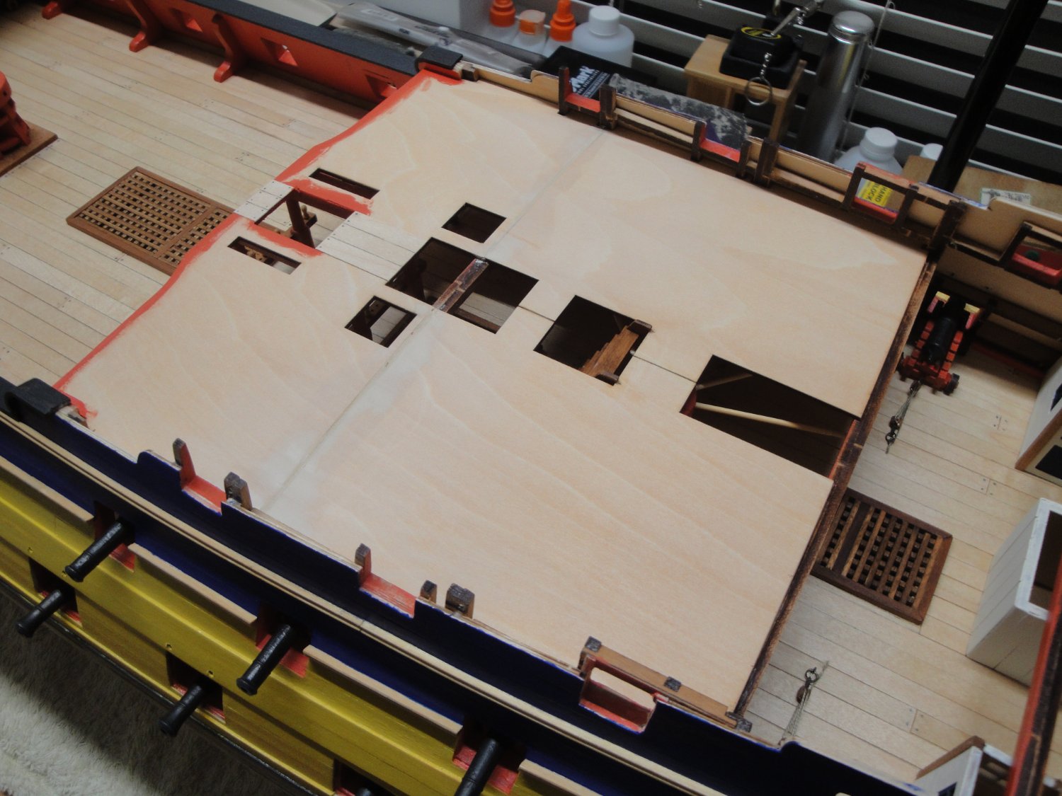
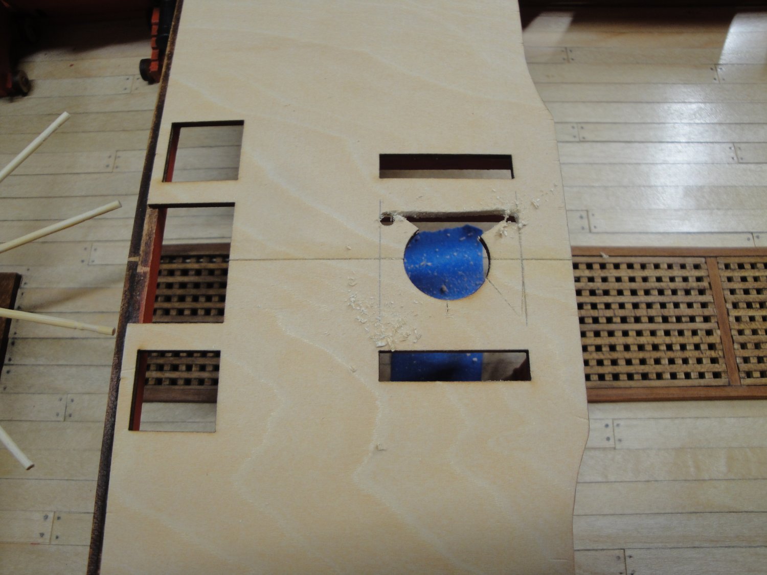
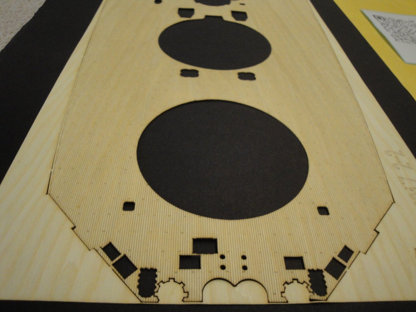
Moving along with the rear quarterdeck. The opening provided in the kit is not right (round opening) for the main mast: Therefore, it is necessary to perform some surgery.... and turn it into a square opening. I suppose the round opening may have been created to position exactly the sub-floors in relation to the main mast. We will give CAF the benefit of the doubt..... Yves