yvesvidal
-
Posts
3,622 -
Joined
-
Last visited
Content Type
Profiles
Forums
Gallery
Events
Everything posted by yvesvidal
-
 Chuck, Will it be CNC carving or 3D printing? Or hand carving... 😁 Yves
 -
I have always wanted to build this ship at 1/100 scale. I started when I was a kid at 15 years old, and did not go further than the bridge and main turret. The guns were made of brass tubes soldered together and raised when spun (like the old Lindberg model). I will be following your build. The Trumpeter kit is a good base to magnify the parts. You should also consider 3D printing some of the repetitive parts. Yves
- 9 replies
-
- 6
-

-
- German
- Battleship
- (and 1 more)
-
This is fantastic of details and realism. Yves
- 200 replies
-
- 5
-
-

-
- Transport No. 103
- Hasegawa
- (and 4 more)
-
Mayflower by tj456 - 1/19 scale
yvesvidal replied to tj456's topic in - Build logs for subjects built 1501 - 1750
I like the old SAE electronics from the 70-80's. I own a SAE 8000 Tuner and like it very much. Great model, by the way. Yves -
The inner planking is quite unusual. Fantastic job. YVes
-
Great collection of pictures. Your models are amazing. Yves
- 200 replies
-
- 4
-
-
- Transport No. 103
- Hasegawa
- (and 4 more)
-
It is coming along nicely. Great work. Yves
-
Dehavilland Mosquito by Edwardkenway - Tamiya -1:48
yvesvidal replied to Edwardkenway's topic in Non-ship/categorised builds
Fantastic job. I would try to drill a little bit, these canons for realism.....It is difficult to say, from the picture. Yves -
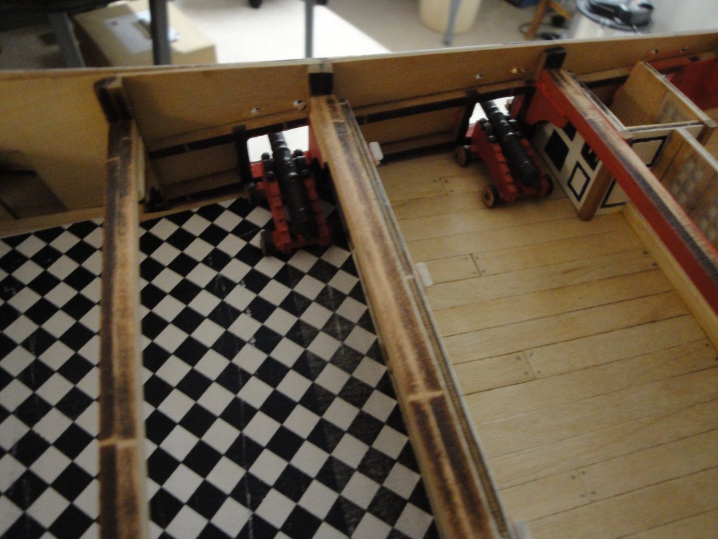
For the separate ovens.... I can fully understand: you don't want your bread or pastries to smell like venison or roasted chickens. For the checkered floor, it (unfortunately) reminds me of the flooring used in all Grand Lodges of the Masonic fraternities, where some significant atrocities are committed. I will not say more about that... Yves
- 106 replies
-
- 3
-
-
- Admirals Barge
- Vanguard Models
- (and 1 more)
-
I never really understood, why the Brits were so fond of these diamond shaped floors.... I did not know they would even place them in their barges (granted, this one is an "Admiral" barge). Any explanations would be most welcome. Yves
- 106 replies
-
- 1
-
-
- Admirals Barge
- Vanguard Models
- (and 1 more)
-
You have been doing some cleaning on your bench.... Very nice. Yves
- 200 replies
-
- 3
-
-
- Transport No. 103
- Hasegawa
- (and 4 more)
-
That is exactly how Revell should have approached these beautiful kits: using spars made of real wood. Yves
- 44 replies
-
- 2
-
-
- Thermopylae
- Revell
- (and 3 more)
-
Great job. Now, you need to source small sheets of thin mahogany to finish the hull, in a similar way to Sea Goddess. Yves
-
Tom from CAF Models, will send you replacement parts, if anything bad happens. Yves
-
Good choice. It looks much better this way. Yves
- 106 replies
-
- 2
-
-
- Admirals Barge
- Vanguard Models
- (and 1 more)
-
I would second your comments completely, as I have the same remarks with the Bellona kit. Fortunately, the hull is planked with limewood which is more suitable for this kind of purpose. I like the cherry tree for details, especially soaked with a liquid orange oil/olive oil/bees wax concoction that I find at Home Depot. Yves
-
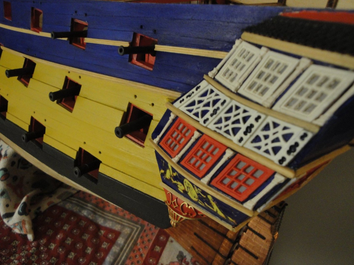
Incredibly beautiful and realistic. It was hard for me to pick up a picture, but I think this one summarizes the excellence of your work. Yves
-
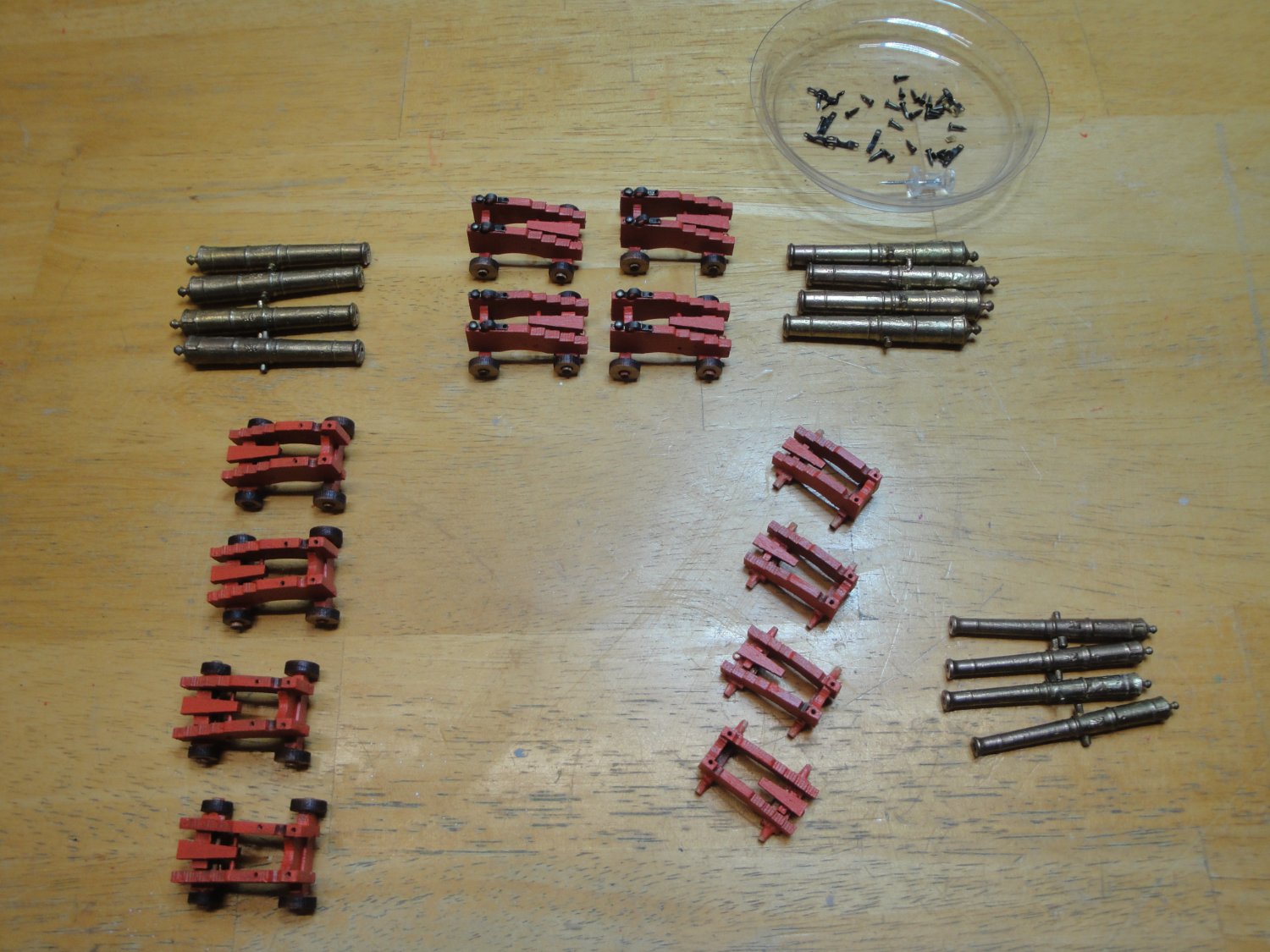
Guns factory: Putting together the remaining 18 pounders and starting some 9 pounders to go on the quarterdeck: Yves

- 507 replies
-
- 16
-
-

-
Great progress on that beautiful hull. Are you planning to use Fujimi bridge and central superstructure or the parts provided with the Nichimo kit? Yves
-
You deserve the title of "King of the Railings". Very impressive work and very realistic. Yves
- 238 replies
-
- 4
-
-
-
- Robert E Lee
- steamboat
- (and 3 more)