yvesvidal
-
Posts
3,641 -
Joined
-
Last visited
Content Type
Profiles
Forums
Gallery
Events
Everything posted by yvesvidal
-

Timber-framed outdoor kitchen - Cathead - 1:1 scale
yvesvidal replied to Cathead's topic in Non-ship/categorised builds
I love your property and what you are doing with it. And most of all, that you can live "off the Grid", pretty much. This will come so useful in the coming months..... Yves -
Very nicely done and filmed. Yes, perhaps a tiny amount of weight on the bow and it will be perfect. I love the sounds of the machinery from underwater....very realistic. Yves
- 55 replies
-
- 1
-

-
- auguste piccard
- submarine
- (and 2 more)
-
The blast bags are incredible, Craig. Could you elaborate how you did them? Thanks Yves
-
Superb work. You made her breasts definitely bigger than the drawing, and this is a very good thing. Yves
-
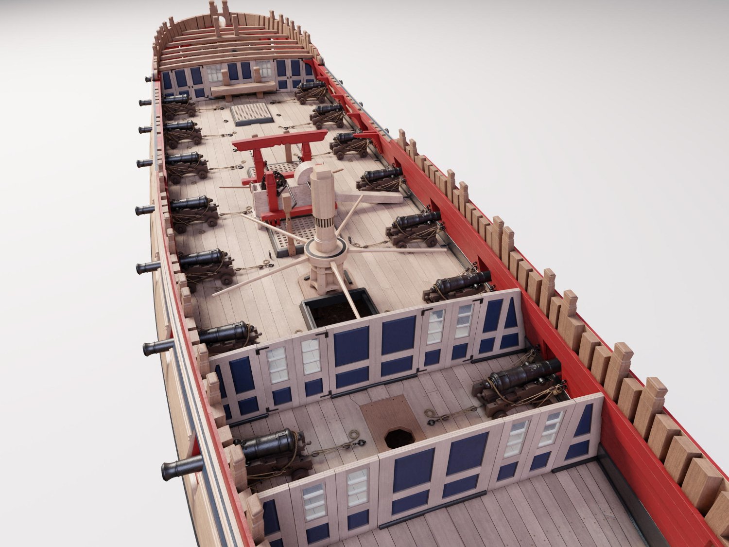
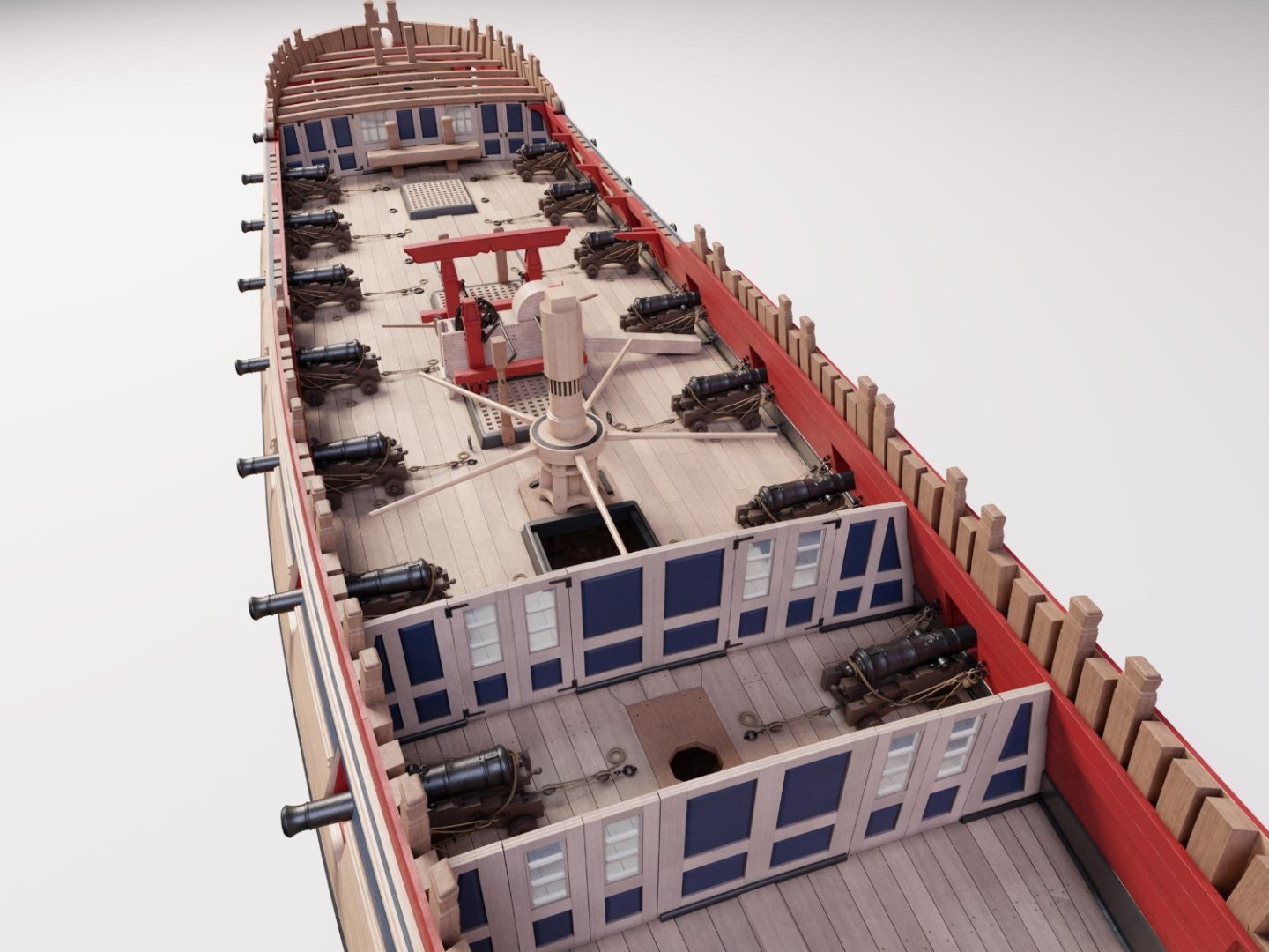
For the internal arrangement, I am taking some inspirations from this picture: This is from a fantastic web site: https://blenderartists.org/t/hms-pegasus-full-ship-building-in-progress/696956/49 Yves
- 507 replies
-
- 12
-
-

-
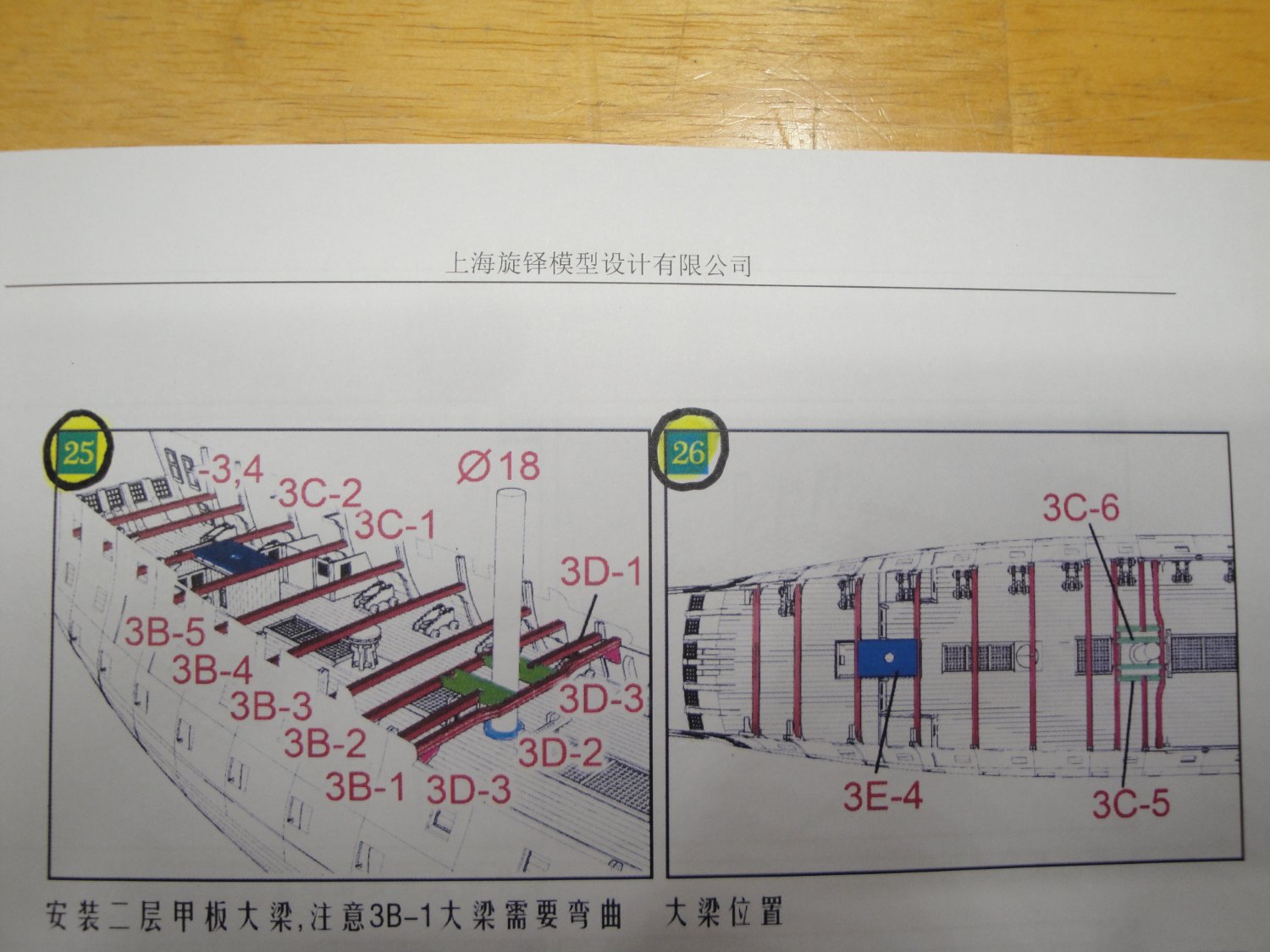
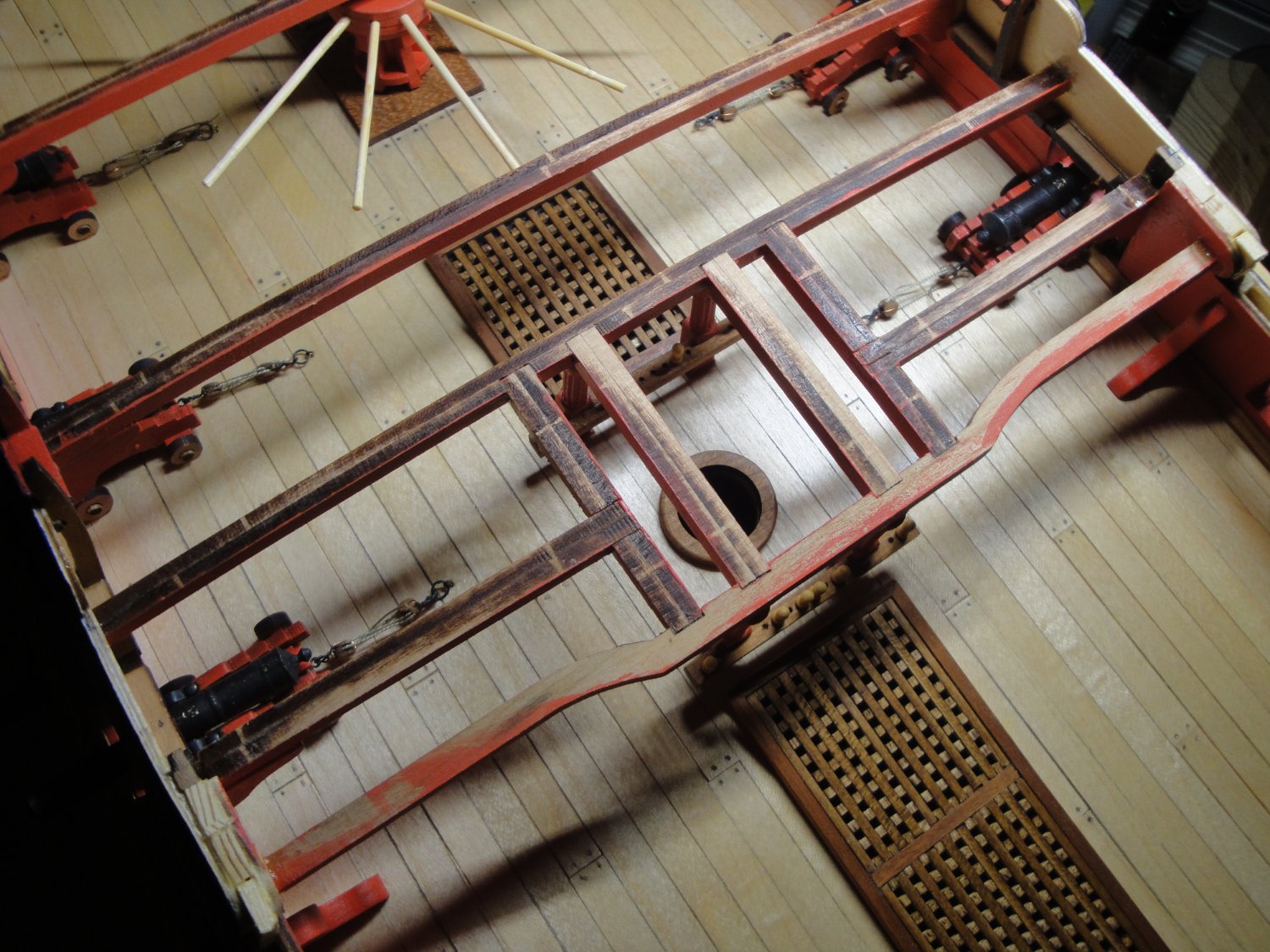
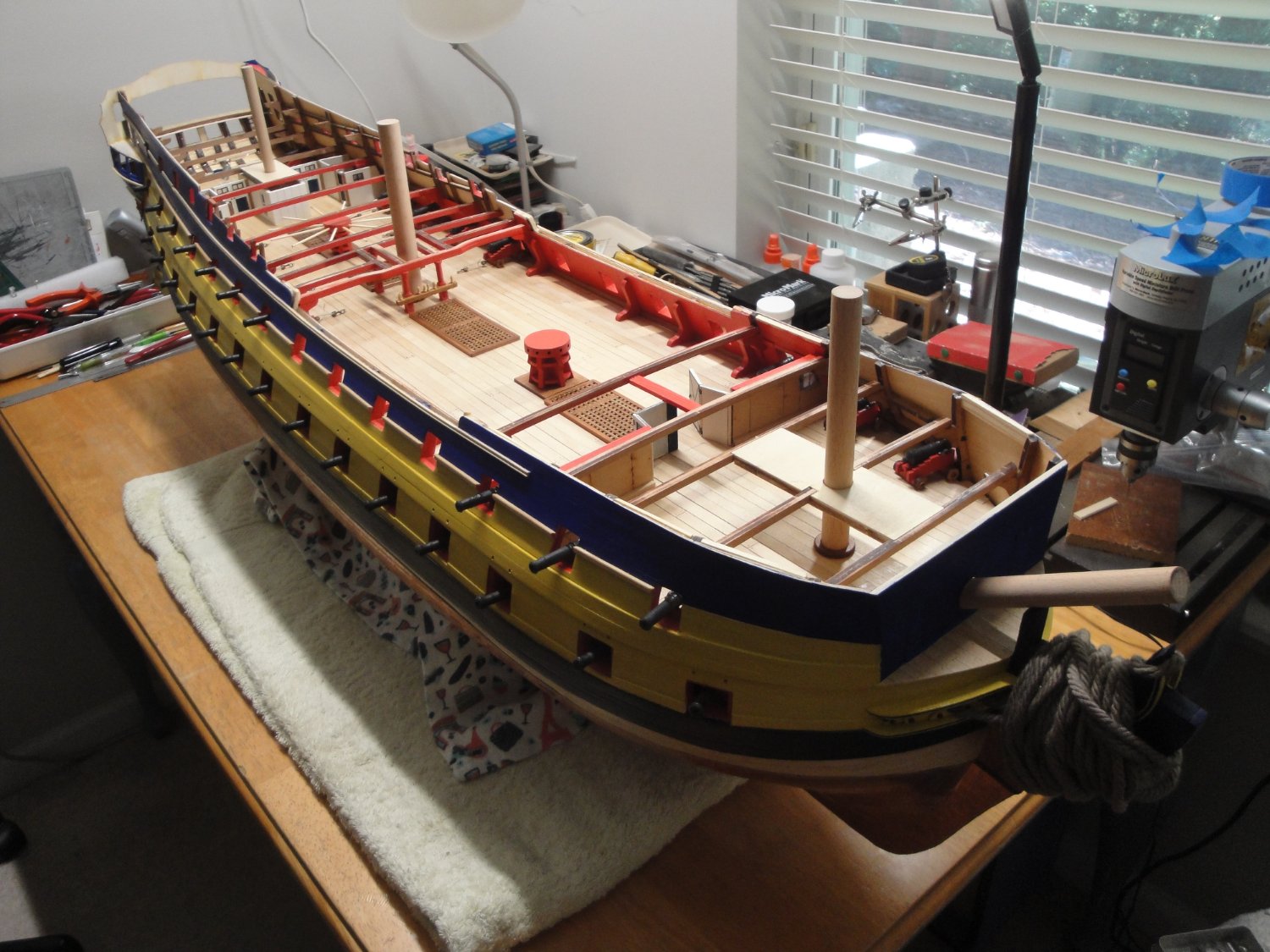
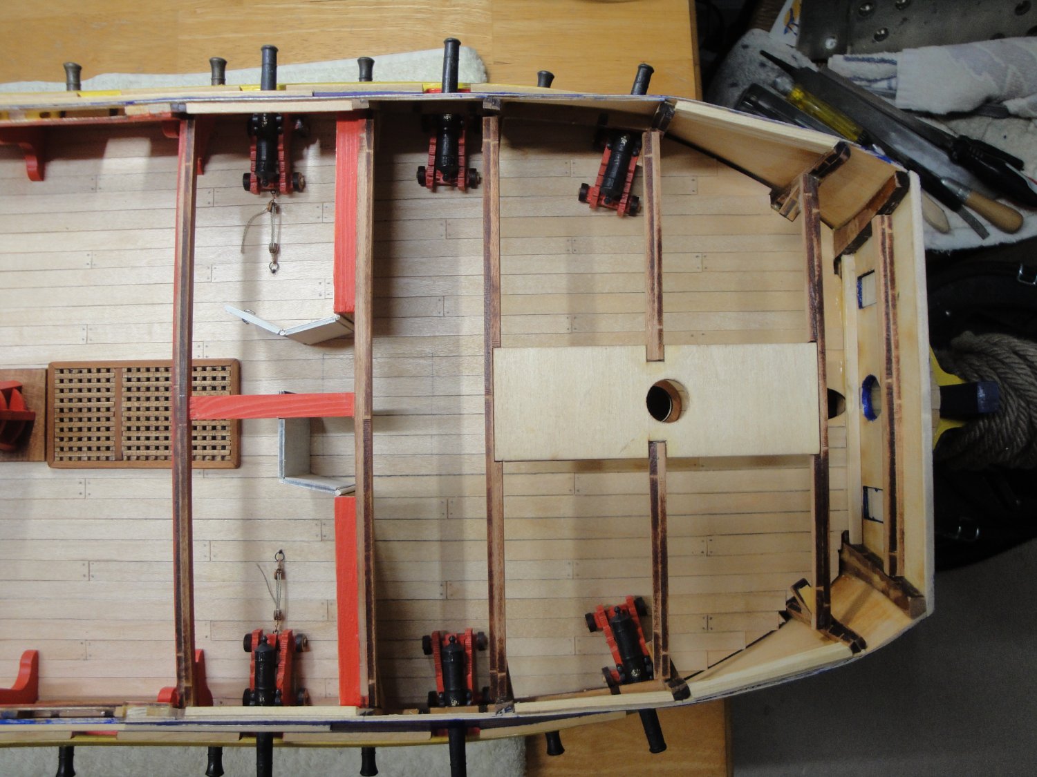
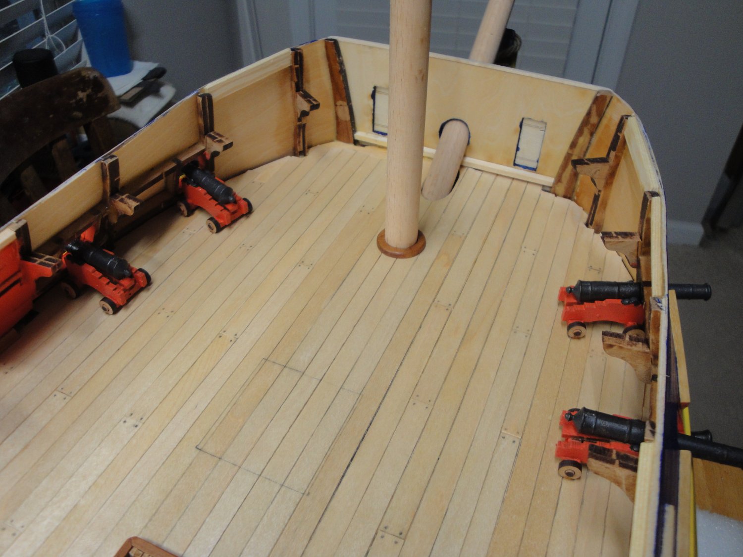
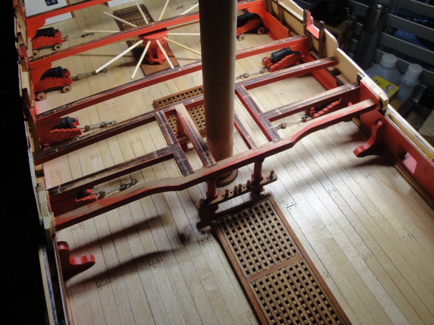
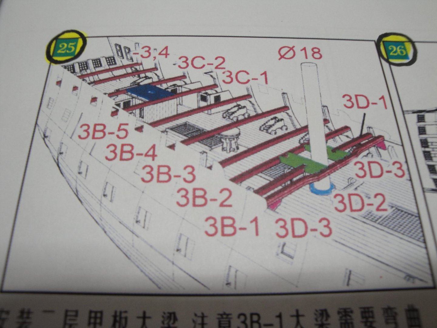
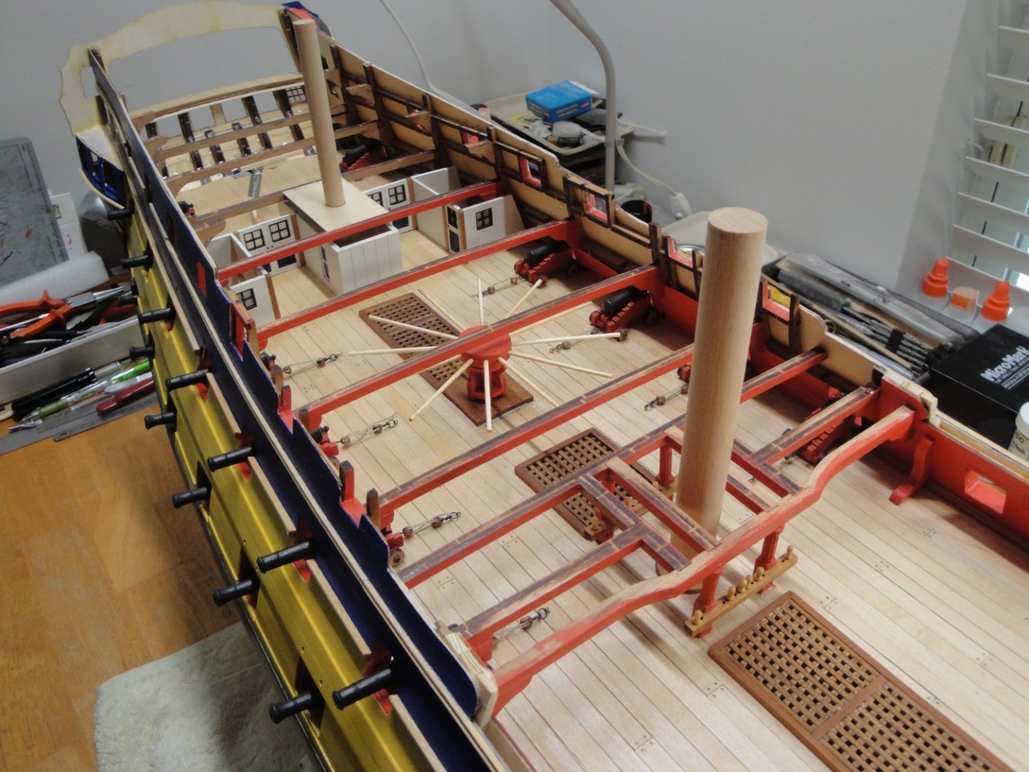
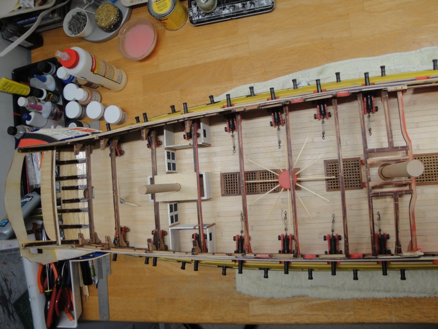
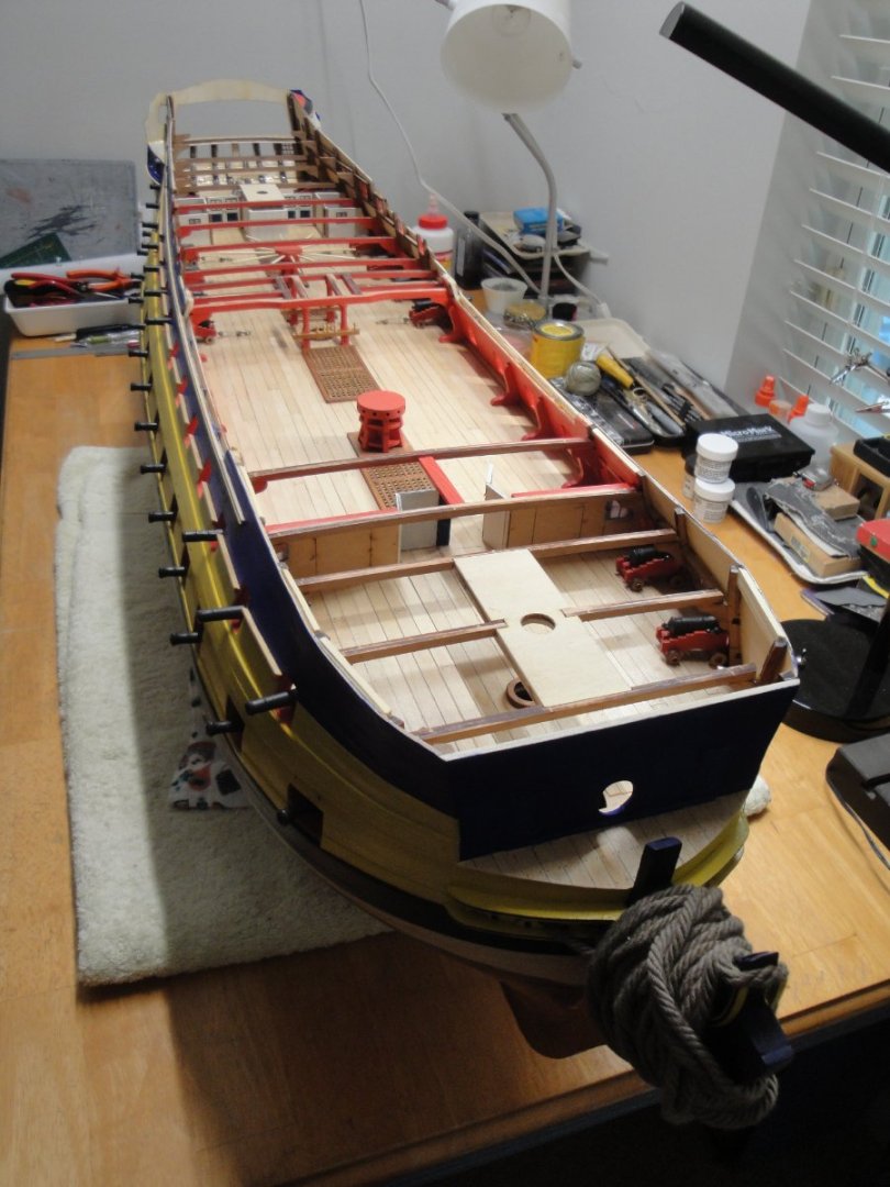
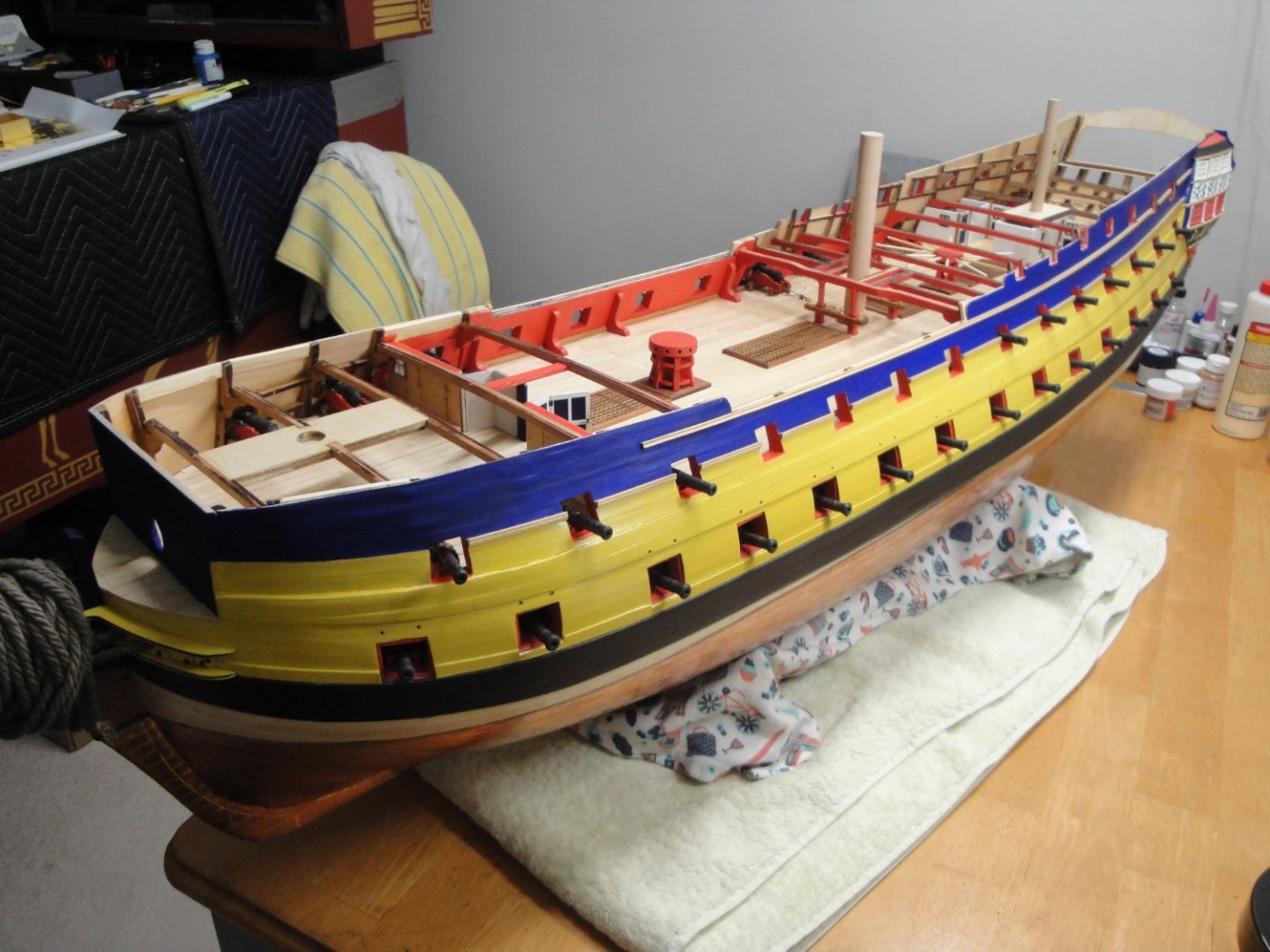
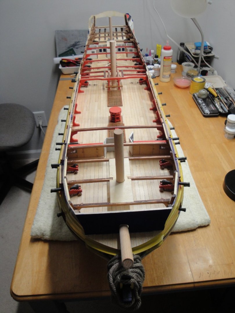
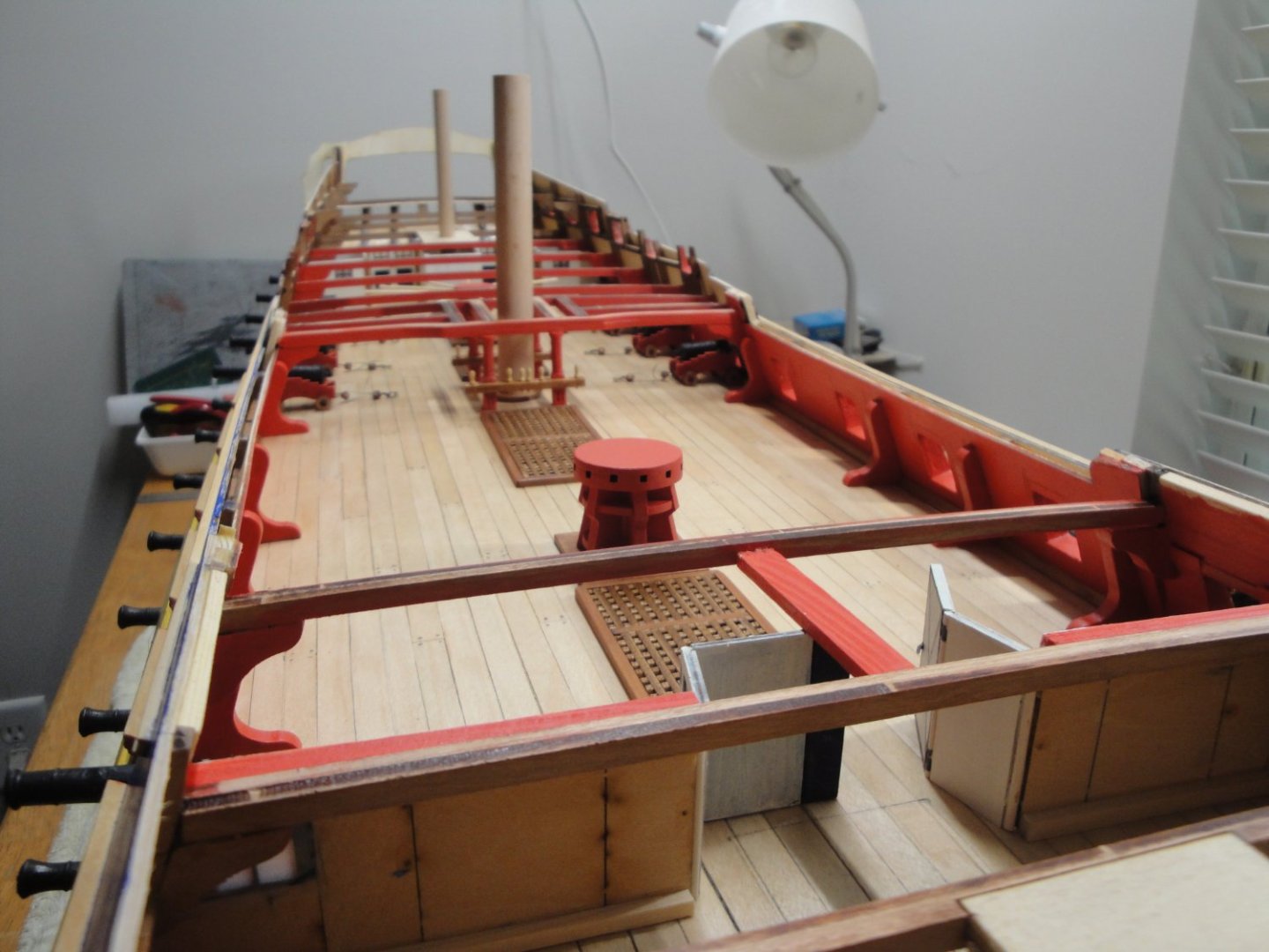
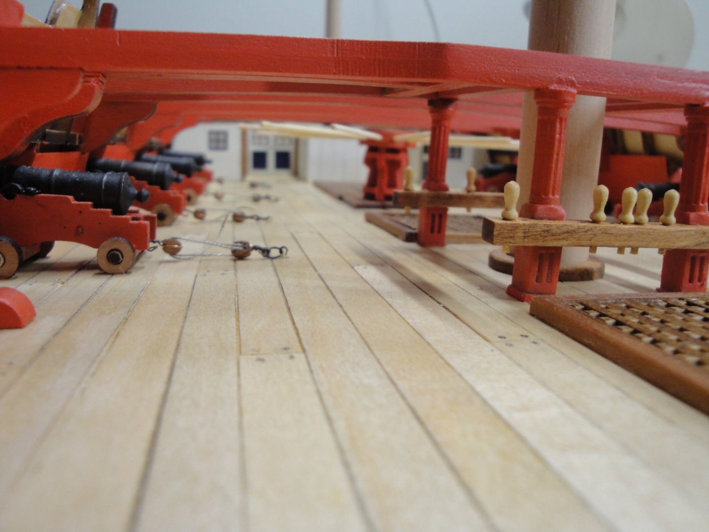
More on Session #4 - The rear cabins under the rear quarterdeck were already built and I completed the beams structure on top of it: The section around the main mast is delicate and requires some thinking and vision, if you want to make it fit. Of course, the bulwarks must be built before, since the beams are resting against them. At this point, all the beams are in place, all the walls, cabins and guns located under the quarterdecks have been built and glued. Let's take a close look at the overall ship: And a few close-ups: All the above will be covered and most likely very hard to see. Yves


- 507 replies
-
- 23
-
-
-
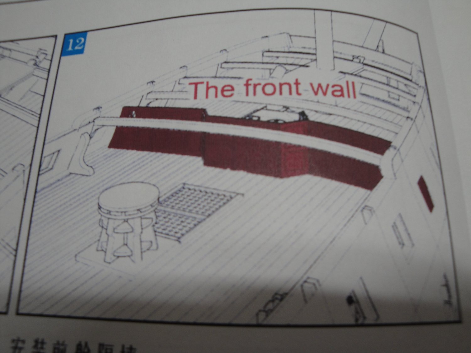
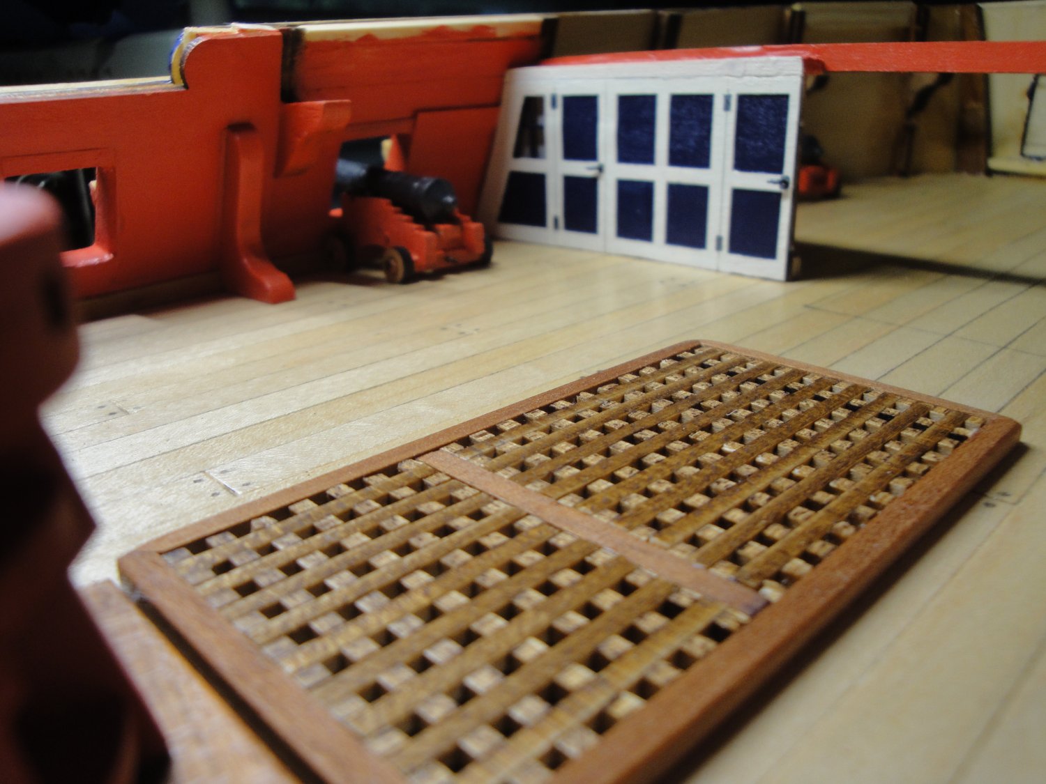
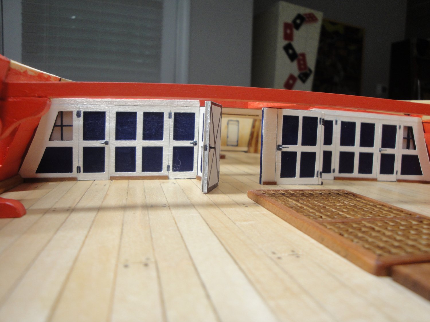
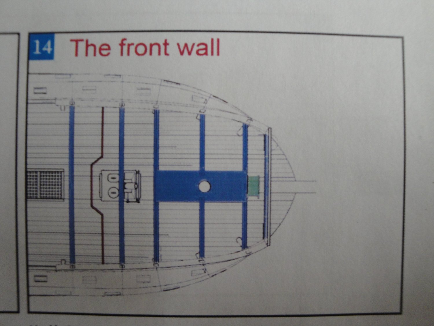
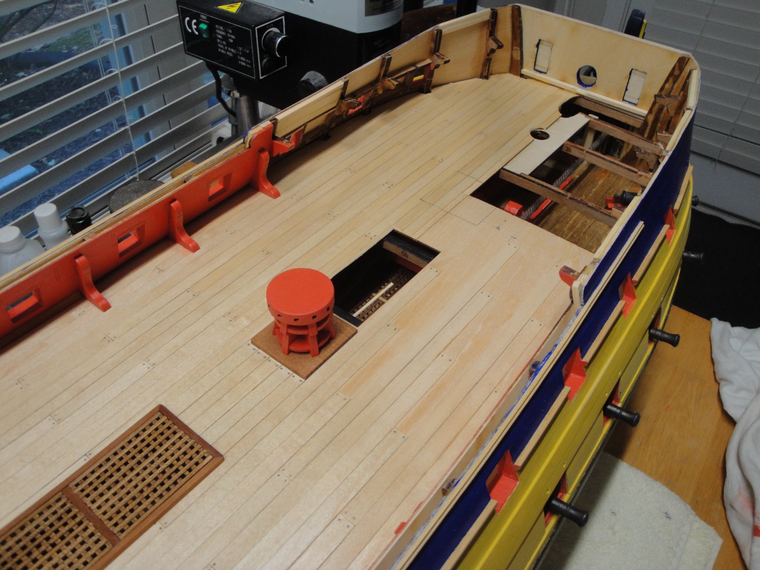
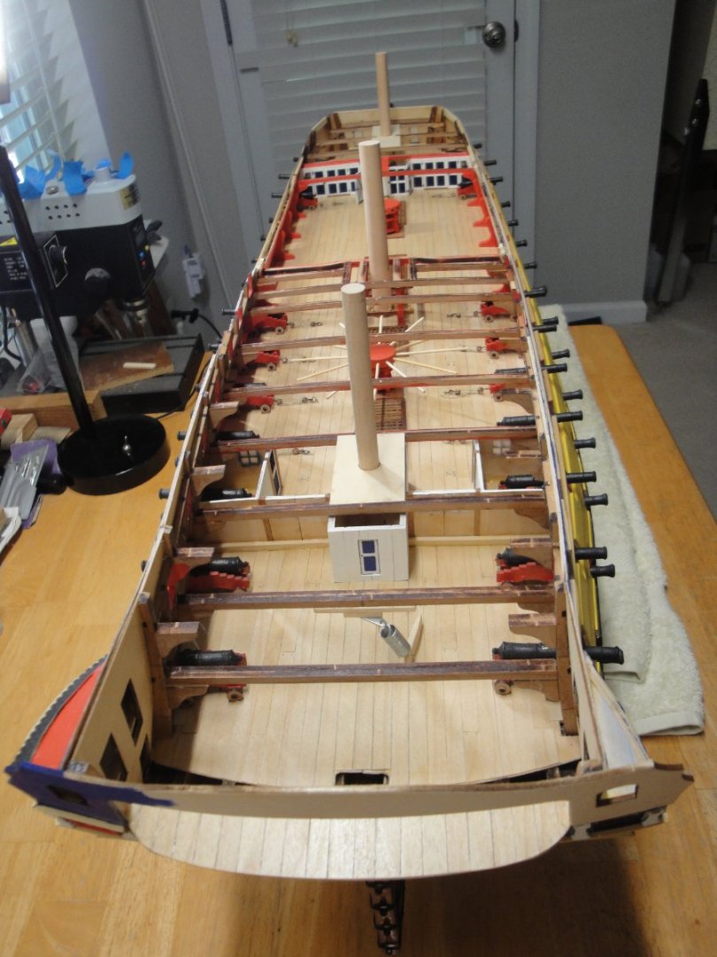
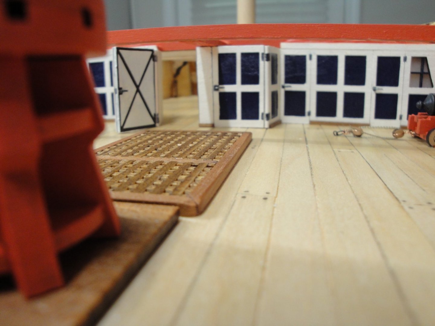
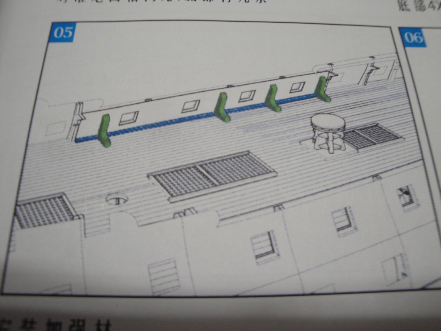
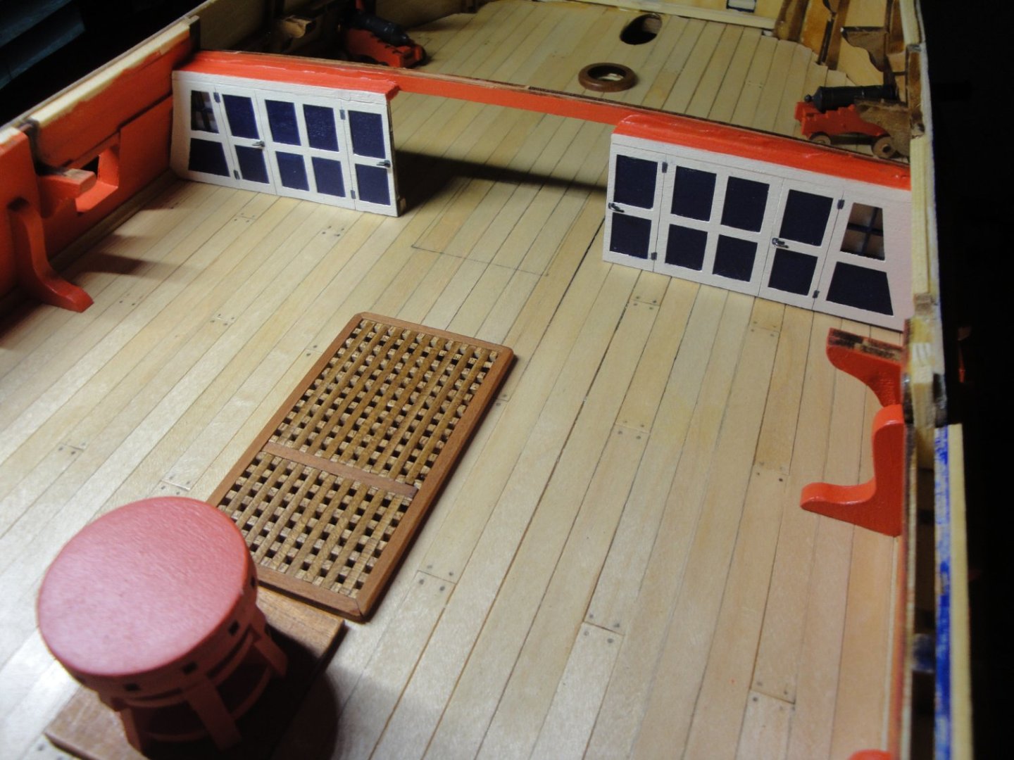
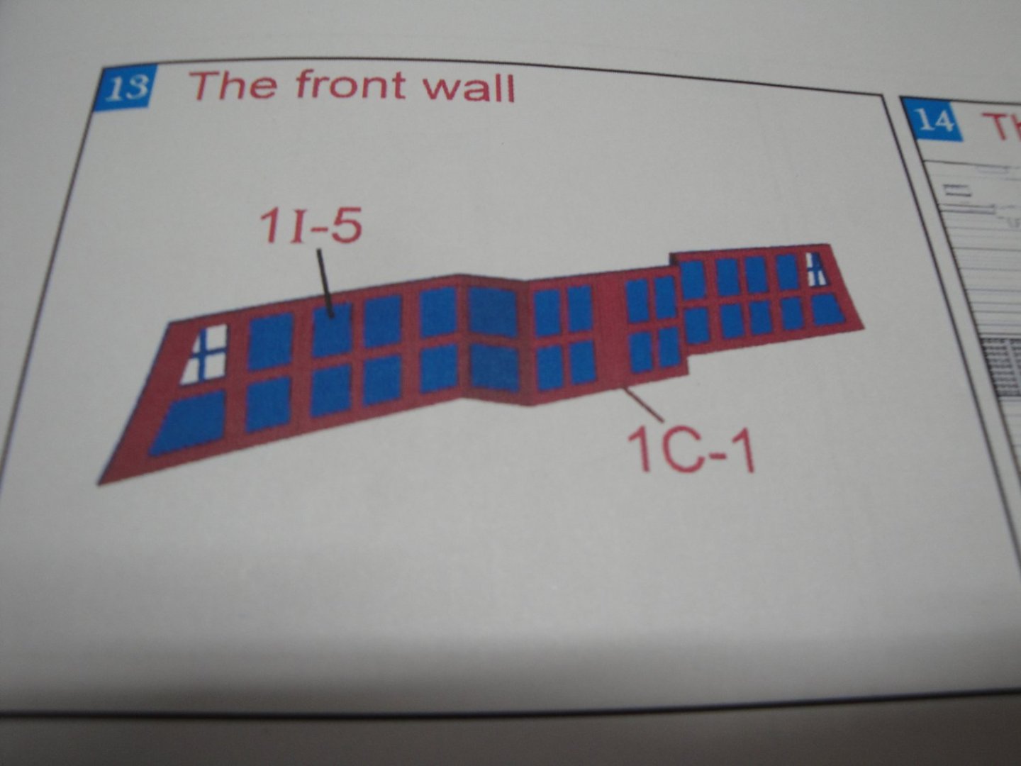
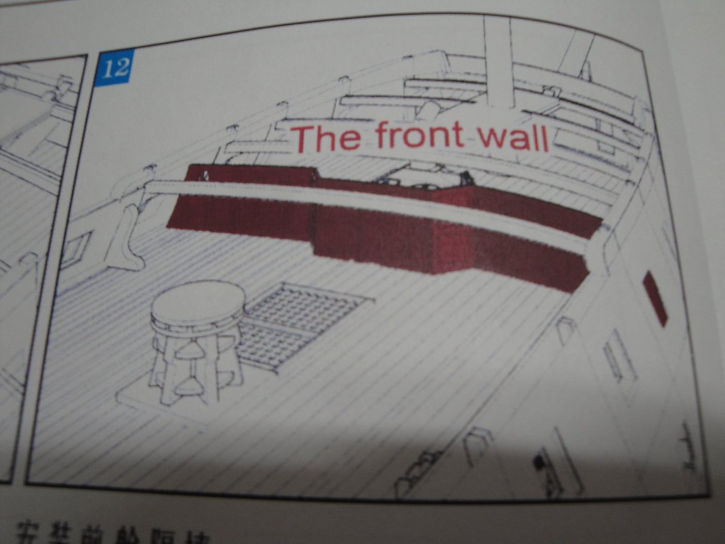
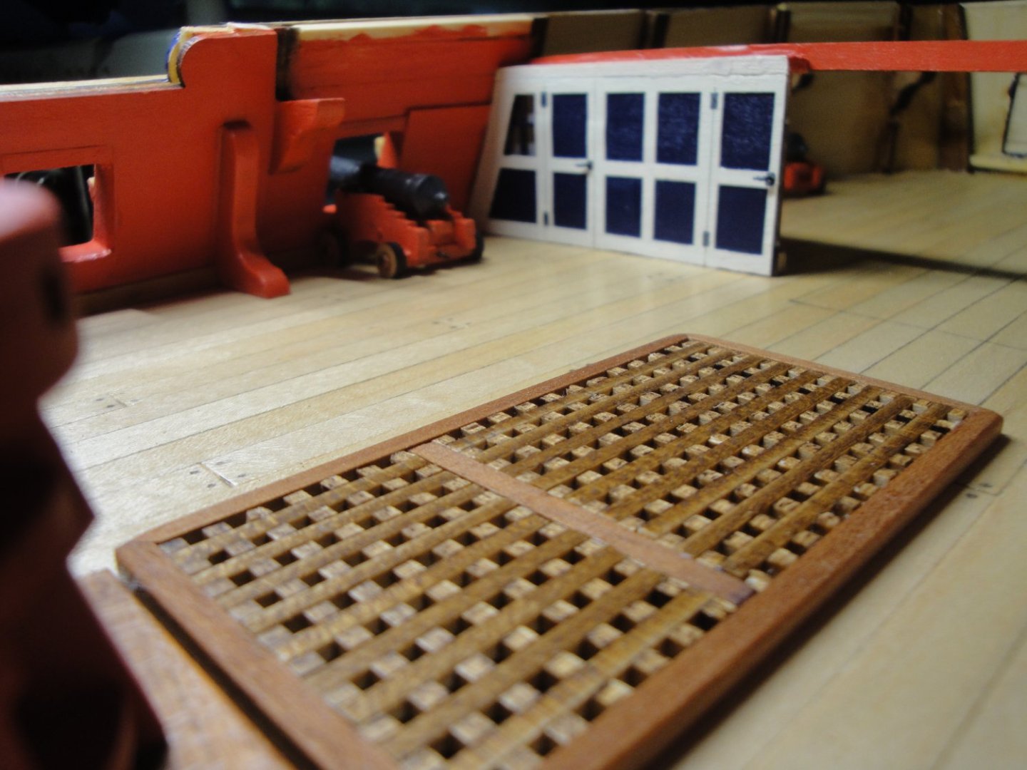
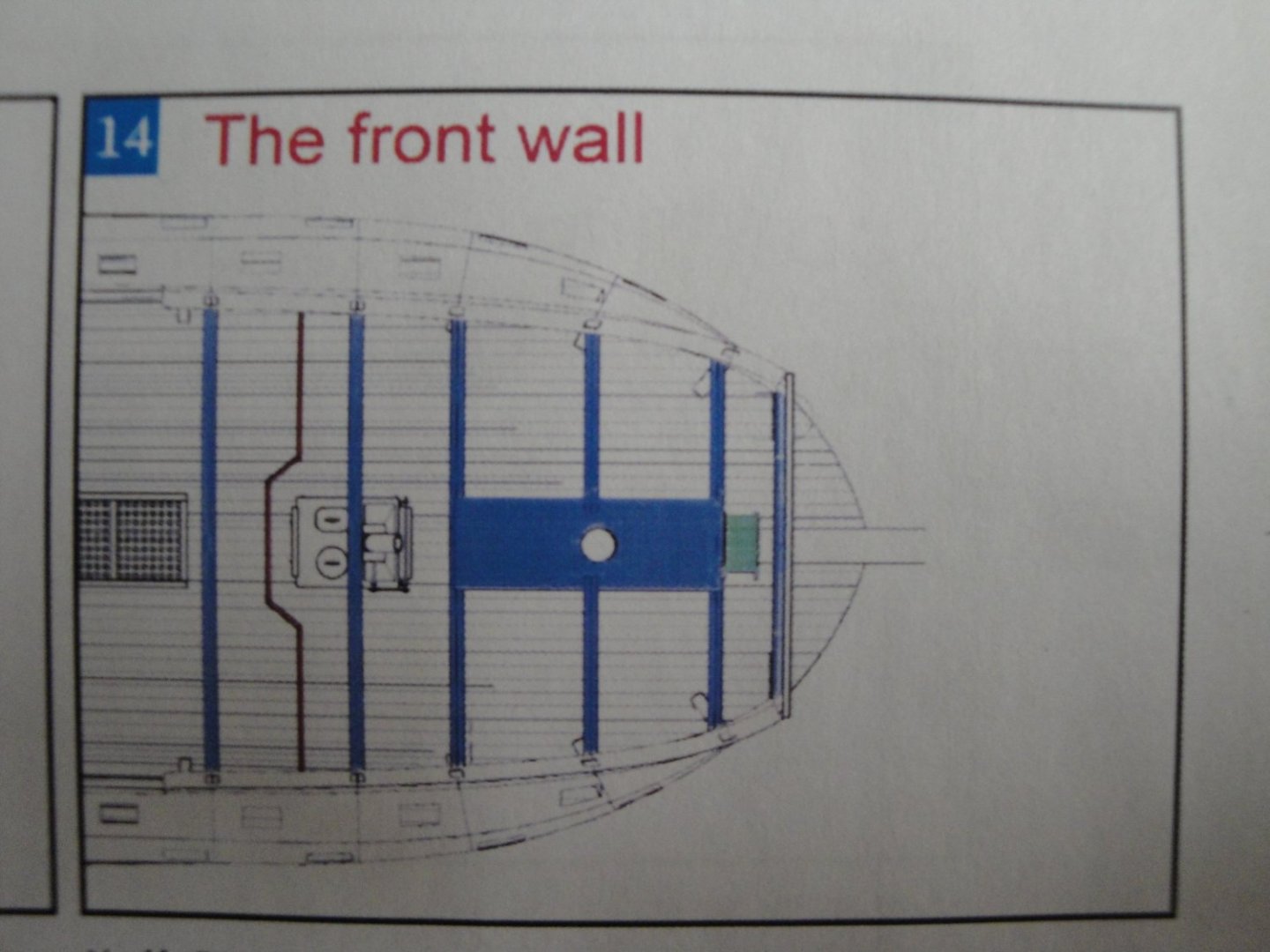
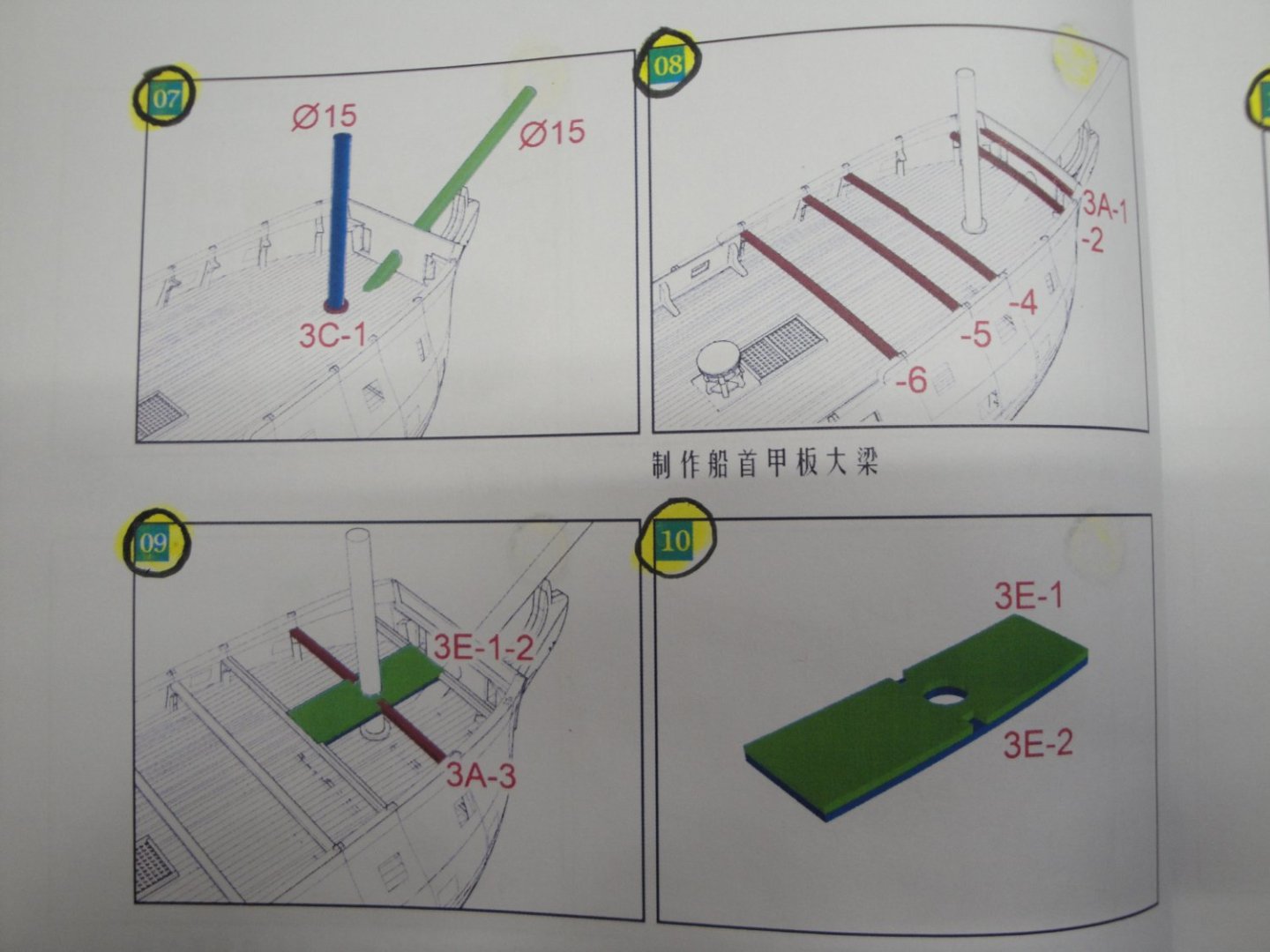
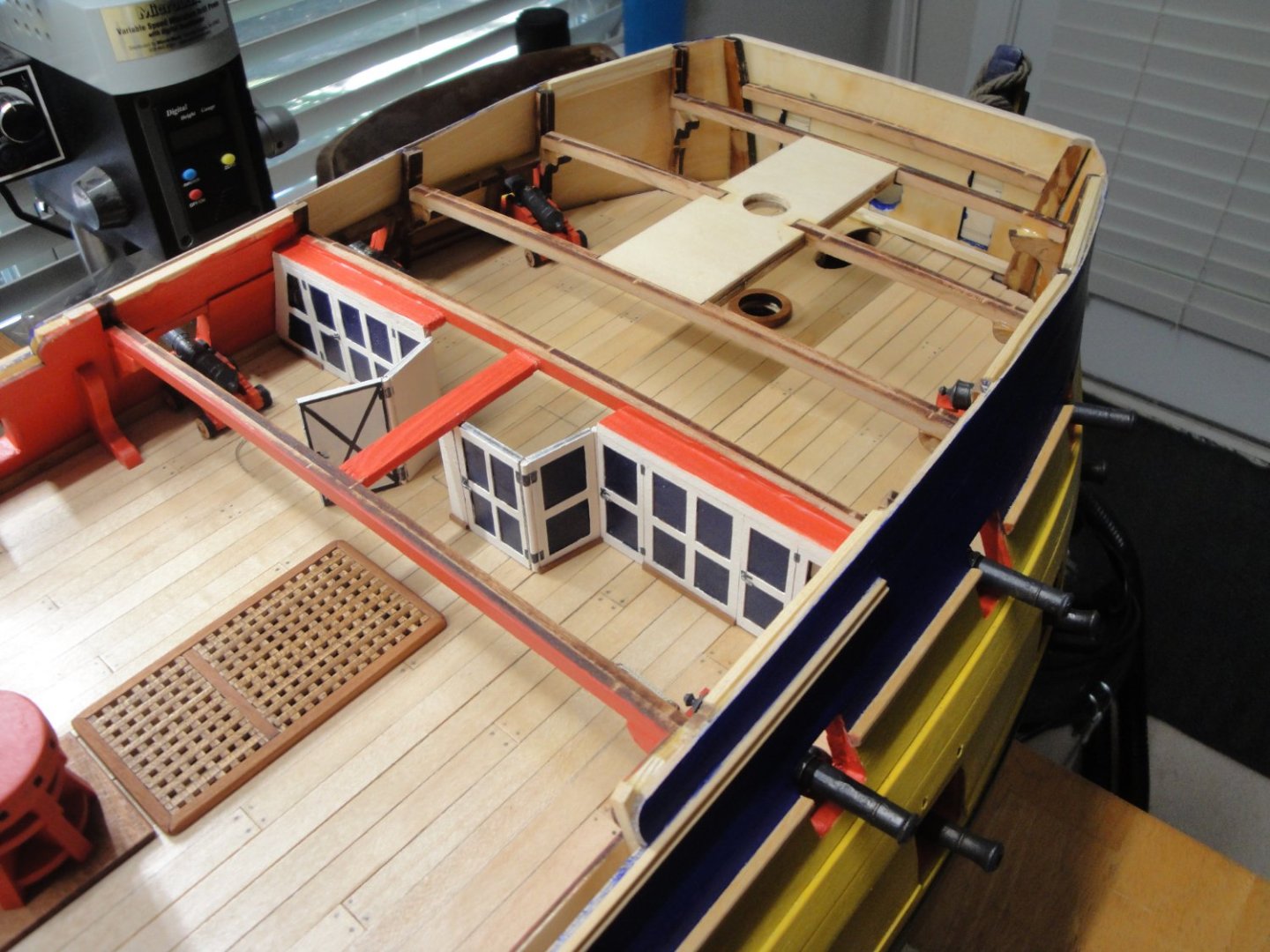
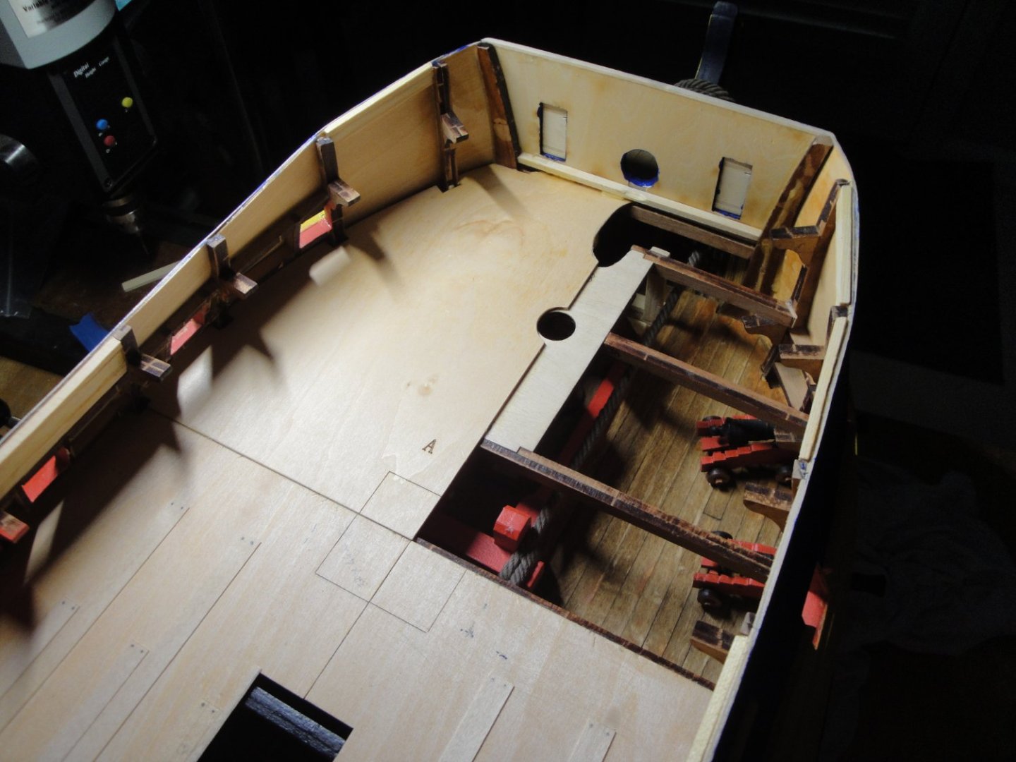
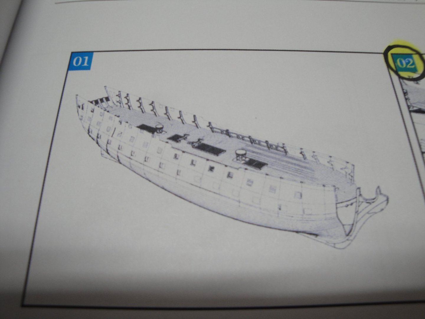
SESSION #4 Although, some work has already been done for Session #4, let's get into more details. Session #4 is covering the front and rear quarterdecks, what goes below them and what goes above as well as the bulwarks, which have been already completed (see instructions below): The kit provides two strips of 4 x 4 mm that must be carved to accommodate the required shape. I wanted to extend these strips all the way to the first rear guns and all the way to the front bulkhead. That can be done, but you have to carve the entire length and be very careful with the cuts. I wish CAF models would provide an additional strip: that would reduce the level of stress on this kit.... In the picture below, you can see what I am talking about: The next phase is the building of the kitchen wall with its two large doors opening on the massive stove. Again, CAF Models does not give you much in term of explanations: I decided to represent one of the two large doors, opened, in order to allow a peak into the kitchen and the stove. Next is the assembly of the beams that will support the front quarterdeck: You can see the additional piece of wood that was added to hold the center part of the large doors. Once the stove is in place, we are now ready to install the floor of the front quarterdeck. Yves


- 507 replies
-
- 14
-
-
You would be almost better off, 3D printing these panels..... Working with Styrene can be a dread sometimes, but PLA (filament) is ten times worse. Yves
-
Fantastic beginnings so far.... Yves
-
You are a Master at carving. Yves
-
Great work Jack, as always. Good to see you back. Yves
-
Great project Craig. I was thinking about doing one, one day, but I will follow your build log with interest. There is a nice implementation of that kit on this French site and you may want to take a look at it, for ideas: https://www.laroyale-modelisme.net/t28739-ijs-yamato-tourelle-armement-principal-de-46cm-takom-1-72-de-geo-6679 I am sure that you will do great, no matter what. Yves
-
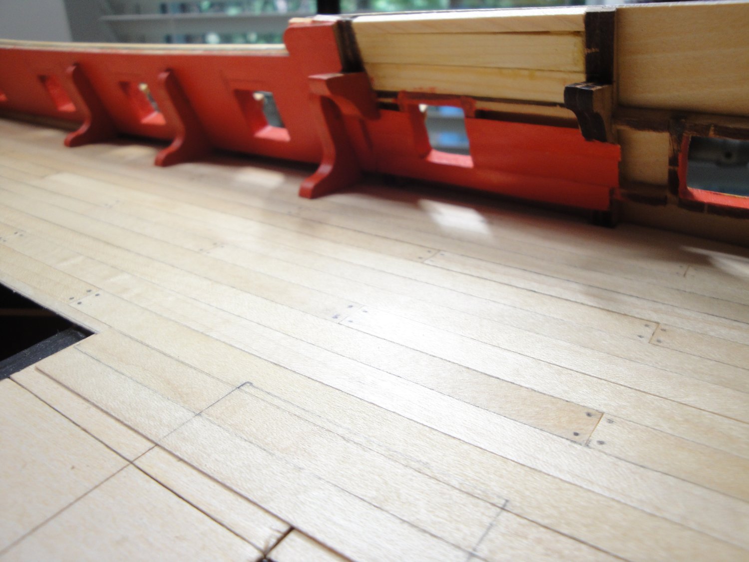
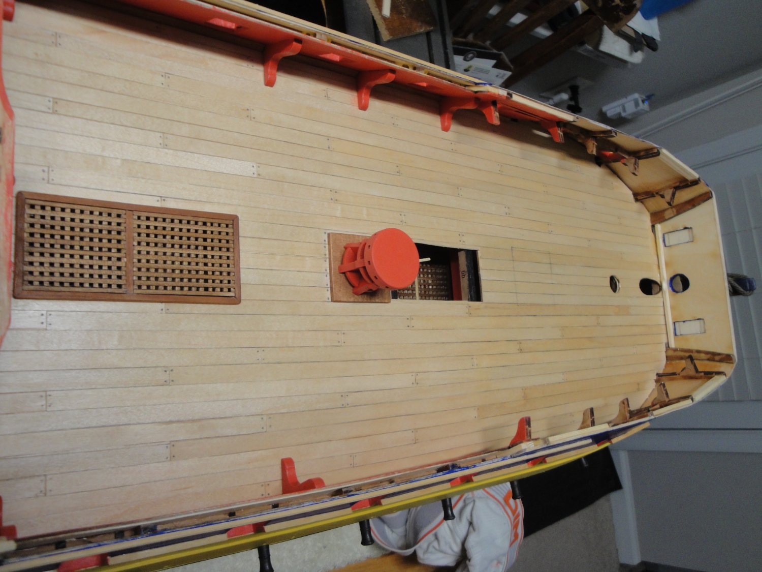
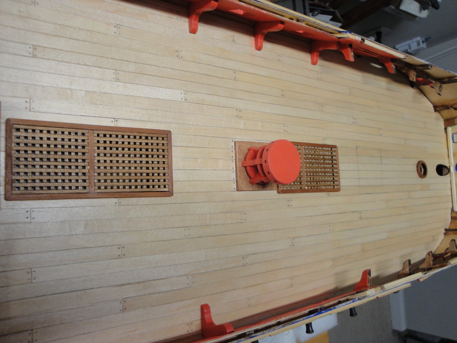
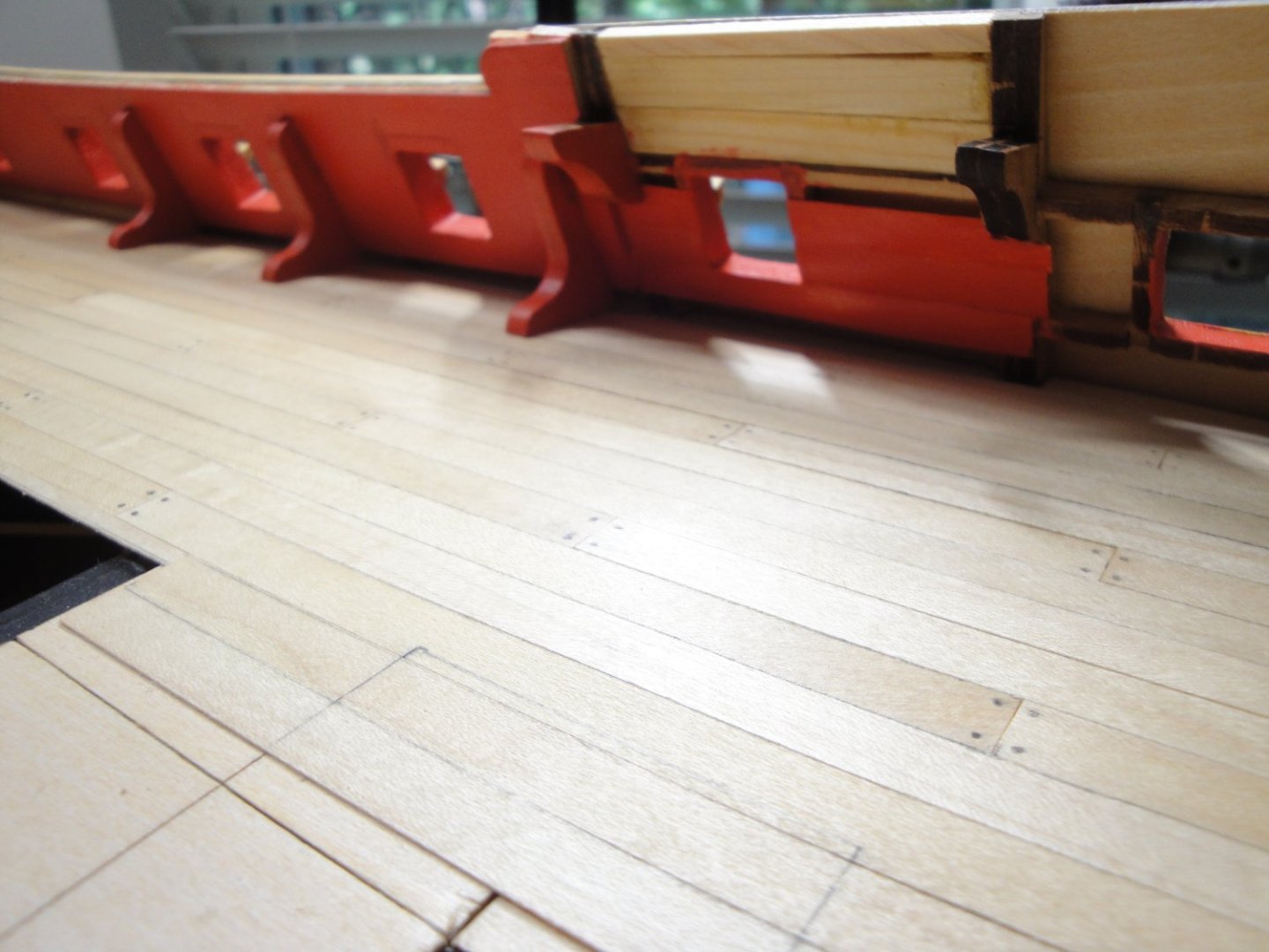
Some progress and the completion of the Session #3. Things went a little bit slow as I was waiting for some extra parts from China (CAF Models). Below is the last section ("A") of the main deck. Half of it has been installed, while waiting for extra length of ropes to arrive from CAF Models. I am envisioning how I will be displaying the model, and some additional ropes may come handy. Tom from CAF Models, was very generous and sent me multiple meters of that beautiful and thick rope, used for the anchors and for pulling the ship on the dry-dock. Being stuck waiting, I started assembling half of the A section: Planking was installed as usual (20 cm long planks): This section of the bulwark will be visible from outside and the kit did not include any covering. I have added the framing and painted it red: The rope arrived, was tied under the main deck to the Bitts, the other "A" section was installed, planking laid down and treated with multiple coats of Wipe On Poly Satin clear. At this stage, Session #3 is almost completed with the exception of the remaining 18 pounders guns, eight of them will be installed at the very end after I get a chance to work on the railing and gangways. Last grate hatch is built and glued: Et voila : SESSION #3 is officially completed !!! Next time, we will be starting the Session #4 (front and rear quarter decks), although multiple strides into it have already been completed. Yves


- 507 replies
-
- 14
-
-
-

-
Kevin, excellent idea to paint the inside of the hull in yellow primer instead of black: It gives that nice warm light, instead of the modern blueish color obtained with LEDs. This Britannic is going to be Titanic.... 🙂 Yves
-
This is starting to look very realistic. Also, it seems that between the parts supplied in the Trumpeter Kit and the PE add/on kit, you may have enough life boats to represent Britannic, correctly. This is a massive endeavor and I will be following your progress with awe and respect, Kevin. Yves
-
Super idea. I have been hoping that someone would attempt that magnificent kit. Changing it to Britannic, is also a great idea. Yves
-
Well, you turned a difficult plastic model into a real gem. Congratulations and thank you for taking us through the building of that kit. I cannot wait to see the map of the river, displayed below your ship. Yves
-
Beautiful little hull. Yves
-
Excellent. I love these dioramas. Yves