yvesvidal
-
Posts
3,622 -
Joined
-
Last visited
Content Type
Profiles
Forums
Gallery
Events
Everything posted by yvesvidal
-
 You are spoiled !!! For the Bellona, there was no words, no explanations and barely a letter to indicate which wood to use. Because of the clinker planking, they gave you some additional information. CAF kits are great and the models very interesting. I wish they could have a James H. to do their documentation and instructions. Yves
 -
I work in silence, too. It is a form of meditation. Yves
-
1936 Rolls Royce Phantom III by CDW - Revell - 1:16 scale
yvesvidal replied to CDW's topic in Non-ship/categorised builds
That purple Super Clean chemical is really great. I use it a lot for all kinds of purposes. Yves- 97 replies
-
- 11
-

-
1936 Rolls Royce Phantom III by CDW - Revell - 1:16 scale
yvesvidal replied to CDW's topic in Non-ship/categorised builds
I wonder how this Gunze/Revell kit compares with the Pocher/Protar/Italeri kits? It will be interesting to see your build. Yves- 97 replies
-
- 10
-
-
You have to rotate them before inserting them.
-
1936 Rolls Royce Phantom III by CDW - Revell - 1:16 scale
yvesvidal replied to CDW's topic in Non-ship/categorised builds
That is an incredibly old kit. I had never seen it before. Yves- 97 replies
-
- 10
-
-
I am going through the same challenges with my Bellona and have decided to no longer follow the suggested documentation. So far, so good. Yves
-
Overall, CAF kits are great and worth being more popular. You, Kevin and I, are pretty much the only active people building them, at this time. Yves
-
My sentiments exactly. Well, at least, you know it is there...... and that will be your satisfaction. Yves
-
When they see you coming at the show with your models, other participants are probably discouraged :-) Yves
-
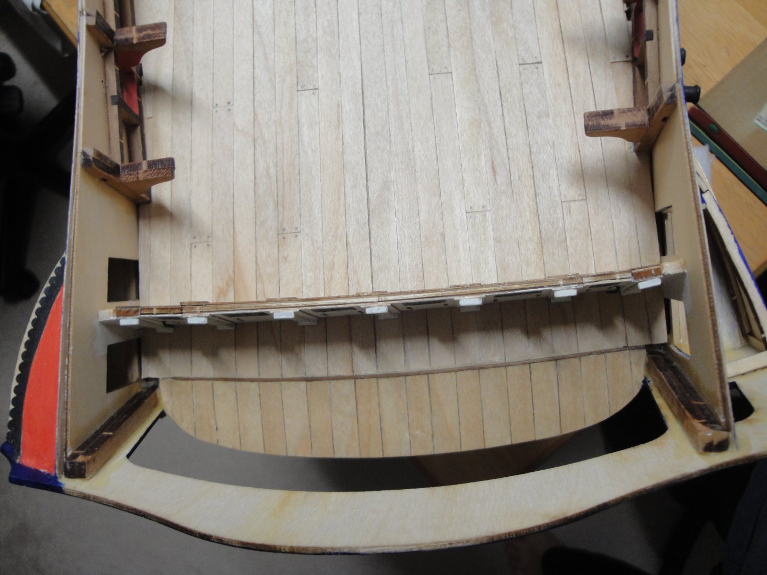
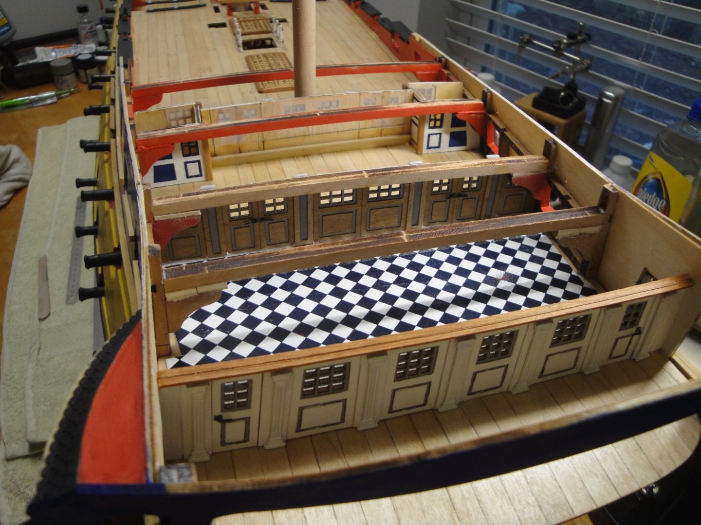
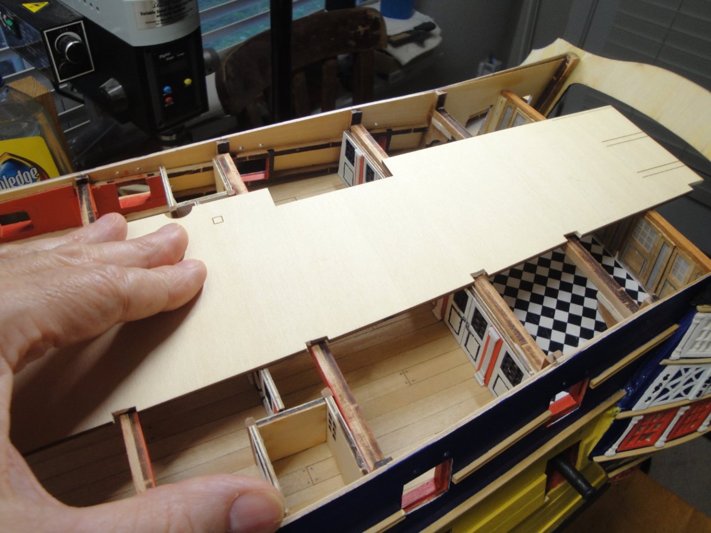
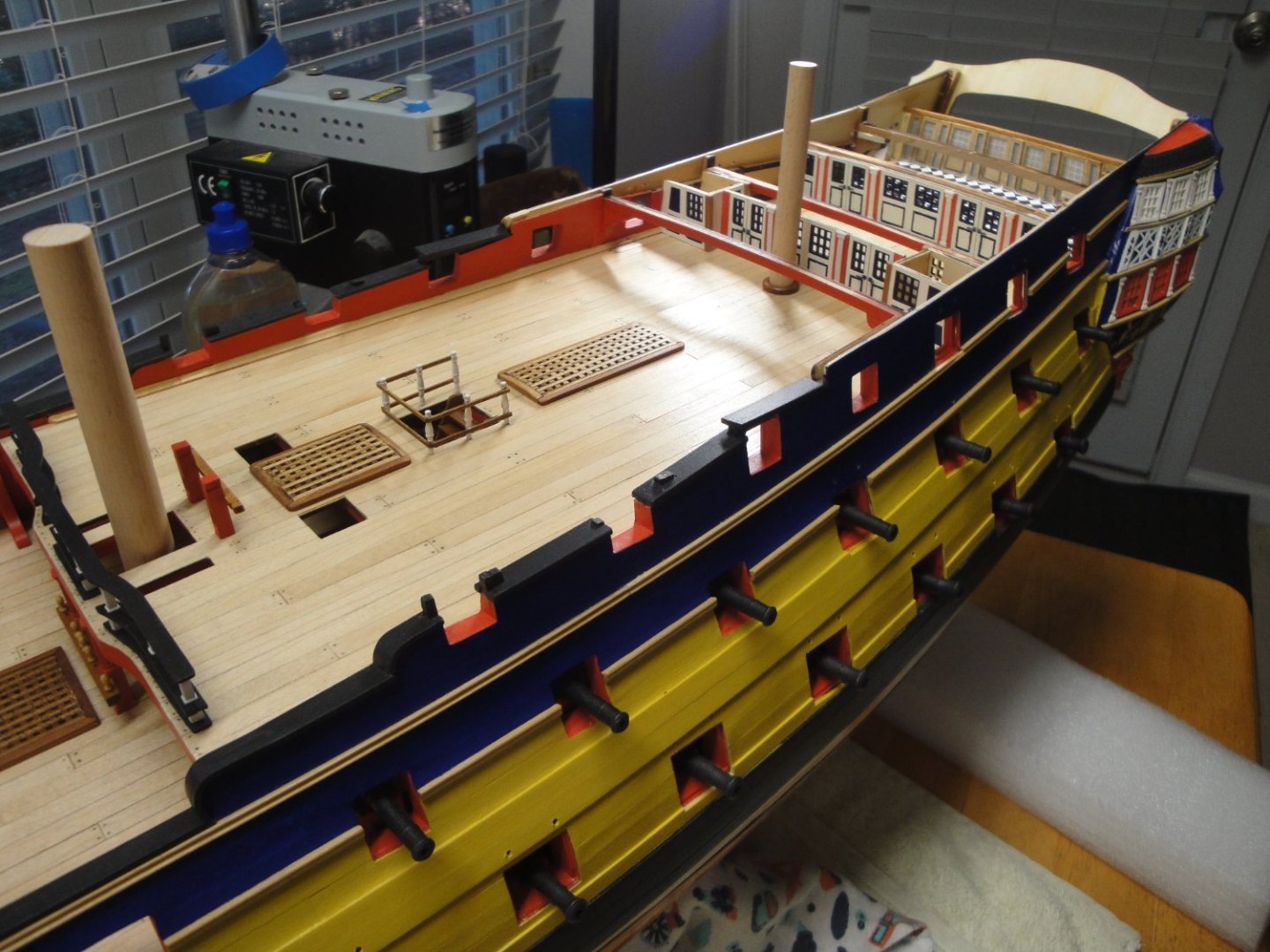
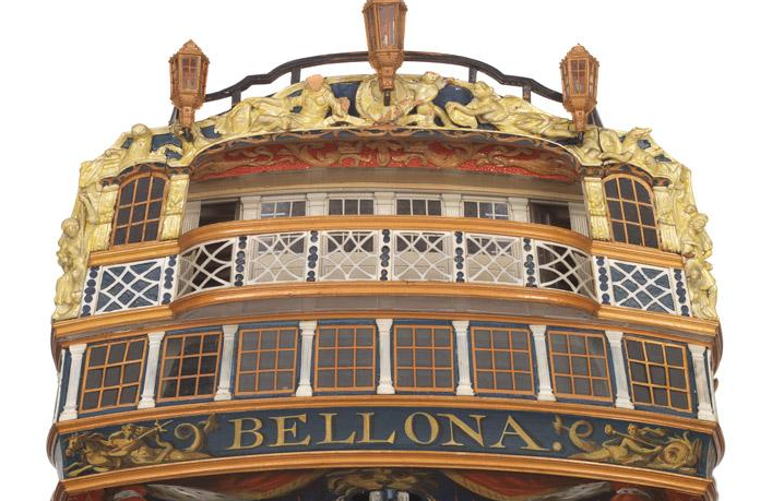
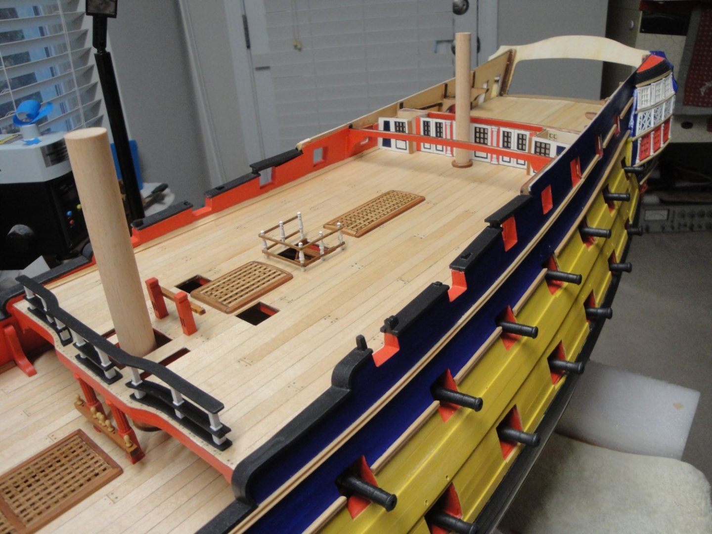
A quick update on the Quarterdeck, with a small improvement and modification of the original kit: The National Maritime Museum model presents a nice molding above the rear bulkhead. That molding is not present in the CAF Model kit and I wanted to add it: I used one of the 2 x 2 mm strips in the Session #4 box and after scrapping it with the correct shape, came up with this sandwich. Instead of the sub-floor going directly against the balusters/columns, I think it offers a little bit more realism for the stern of that ship. You can see (above) how the molding is placed: a 2 x 2 strip sitting on top of the bulkhead and a 2 x 2 strip scrapped and glued to it. It does not cover entirely the top of the balusters, but once the top deck is in place, it will be impossible to see that. Because of the introduction of that decorative molding, the top deck is raised by another 2 mm. At that point, the beams supporting the top deck must be raised to accommodate the change: This is easily done by placing a 2 mm thick piece of wood on top of the elbows, supporting the beams: Once everything is sanded smooth and cleaned, the poop deck fits nicely with just a slight curvature to eliminate the standing water: Note that the installation of these beams is part of the last Session #5. Overall view of the rear section and quarterdeck: Time to move back to the Gallery and the bow. Thank you all for your comments and encouragements, as they are very much appreciated. Yves


- 507 replies
-
- 22
-
-

-
What a beautiful construction. Chaperon is one of my favorite kits.... Yves
- 158 replies
-
- 1
-
-
- chaperon
- Model Shipways
- (and 1 more)
-
With so many life boats, they seem to have learned their lessons, after the Titanic fiasco. Yves
-
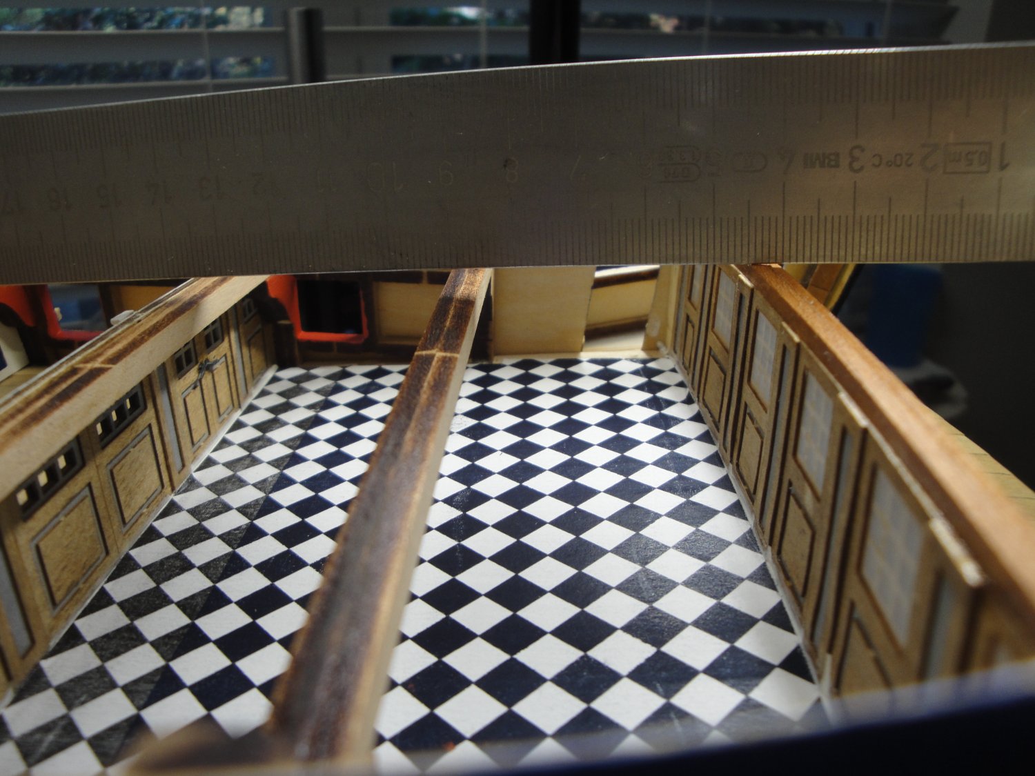
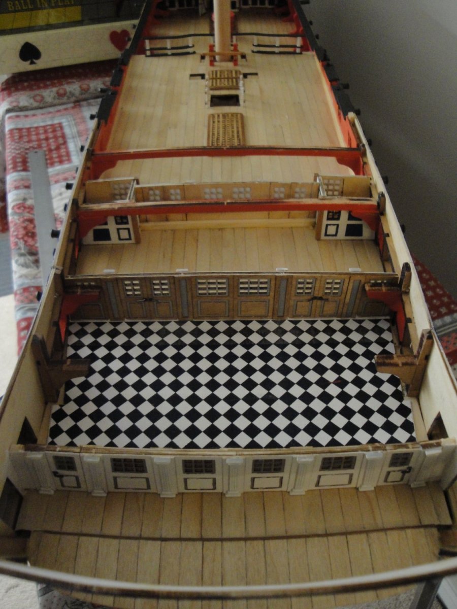
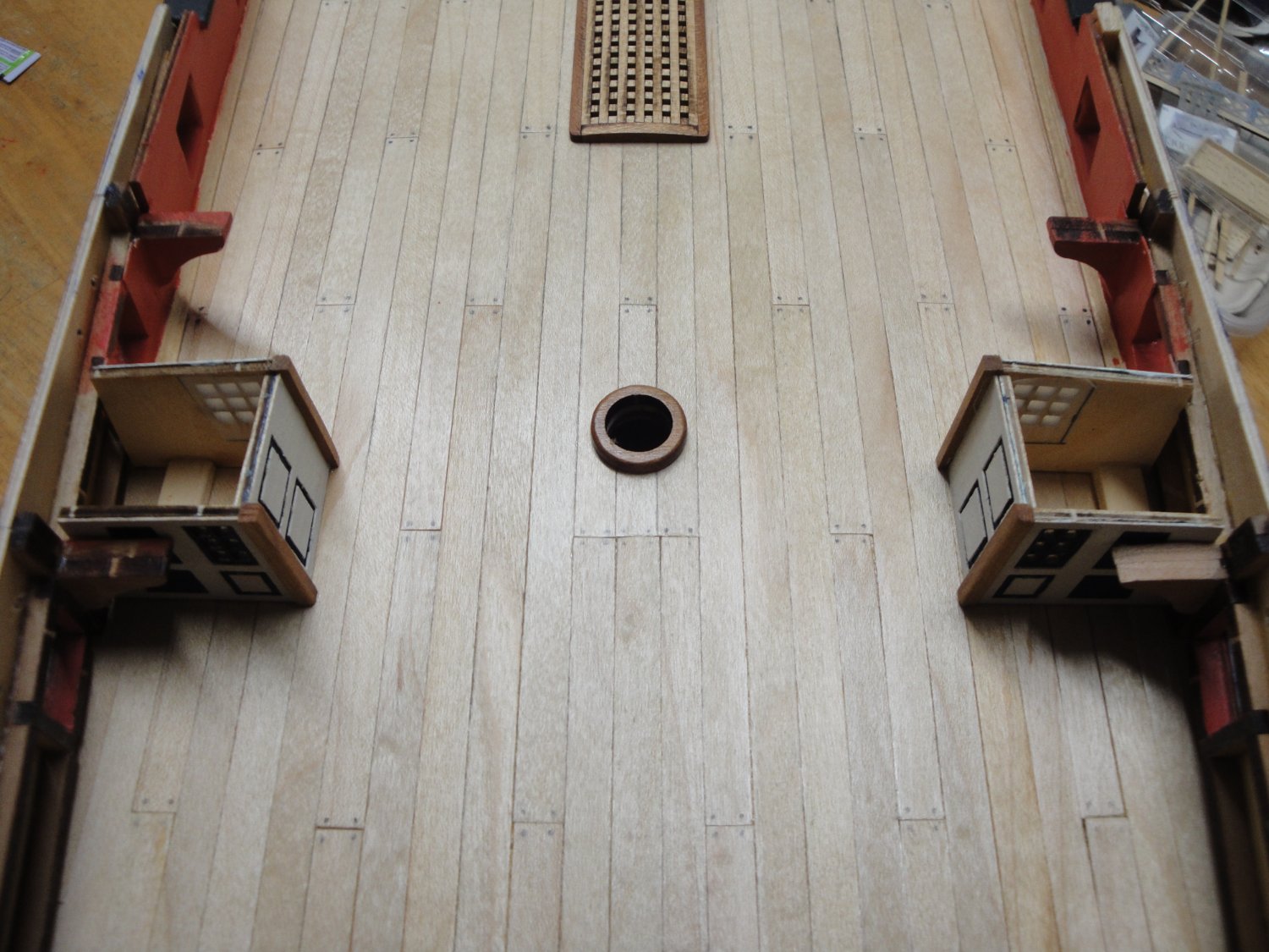
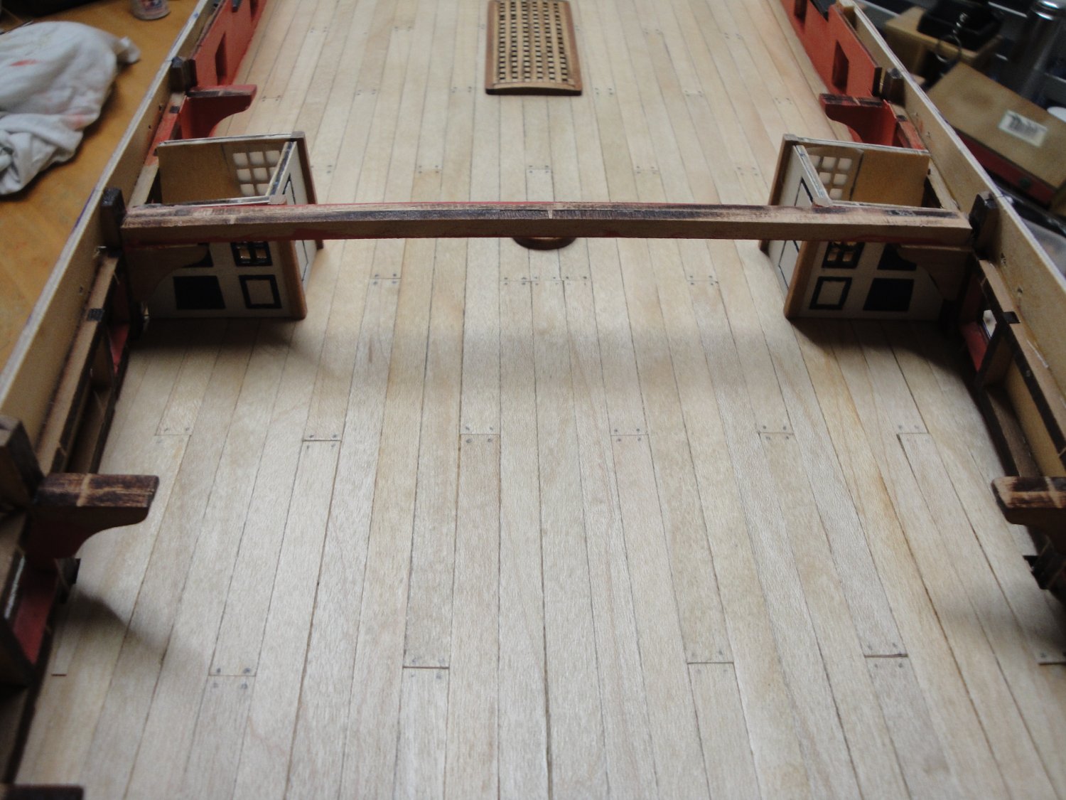
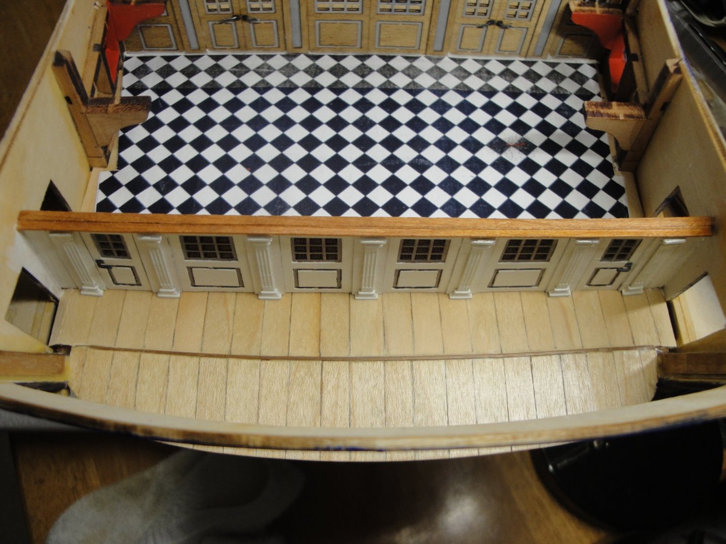
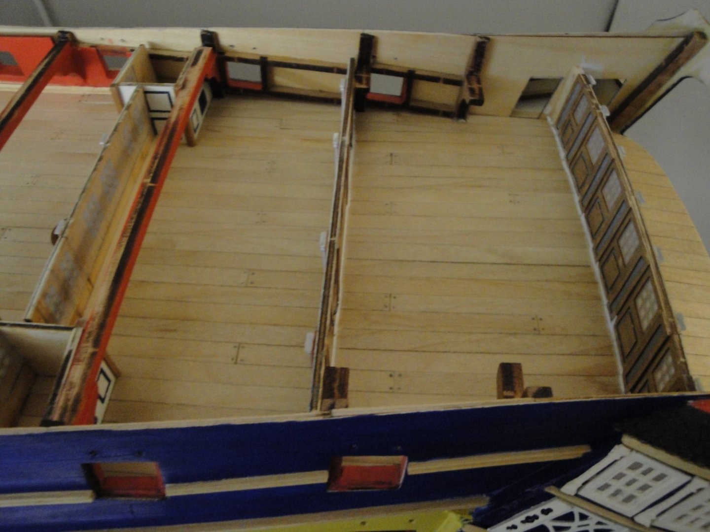
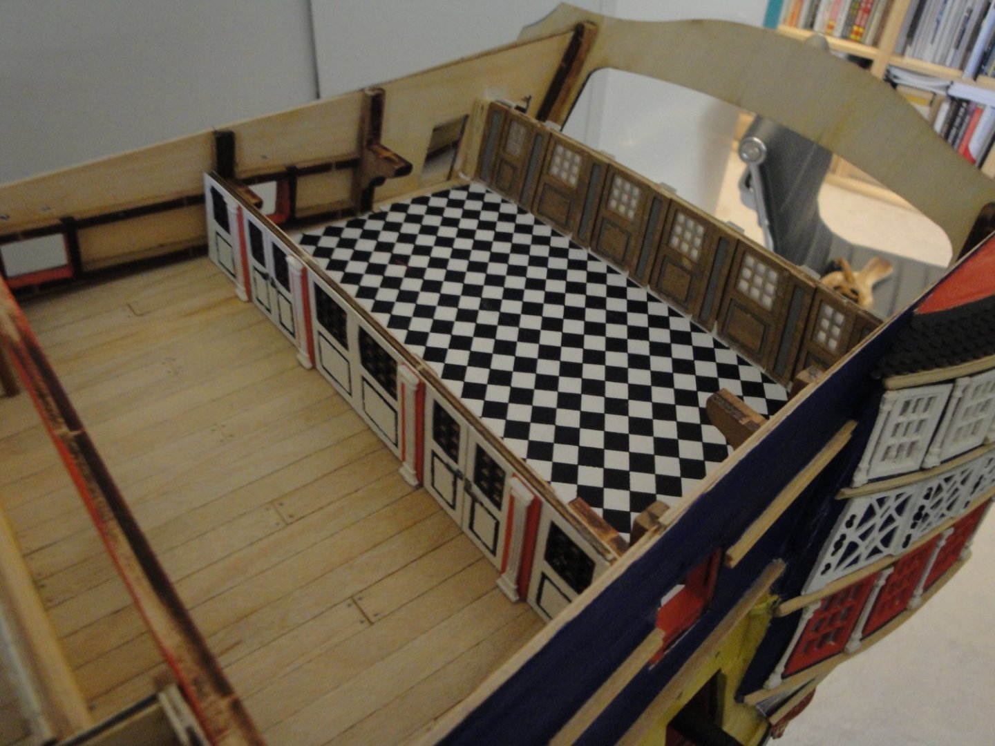
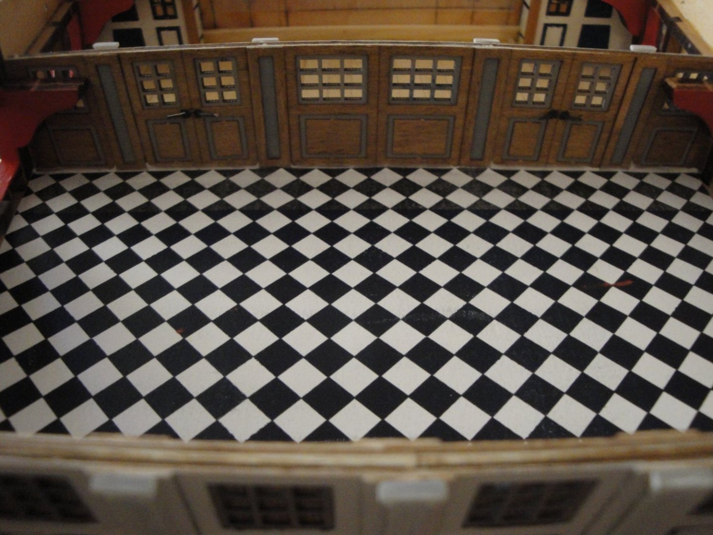
Finally, the building of the bulkhead separating the main cabins: Overall, it is pretty much the same way of building that partition. It is finally glued in place: Not much to see, once the poop deck will be in place: Time to install the diamond floor: That's it, for the quarterdeck. I still have the doors leading to the "Johns/Galleries" to build and a few details and we will be able to close the lid on all this :-( Yves


- 507 replies
-
- 21
-
-
-
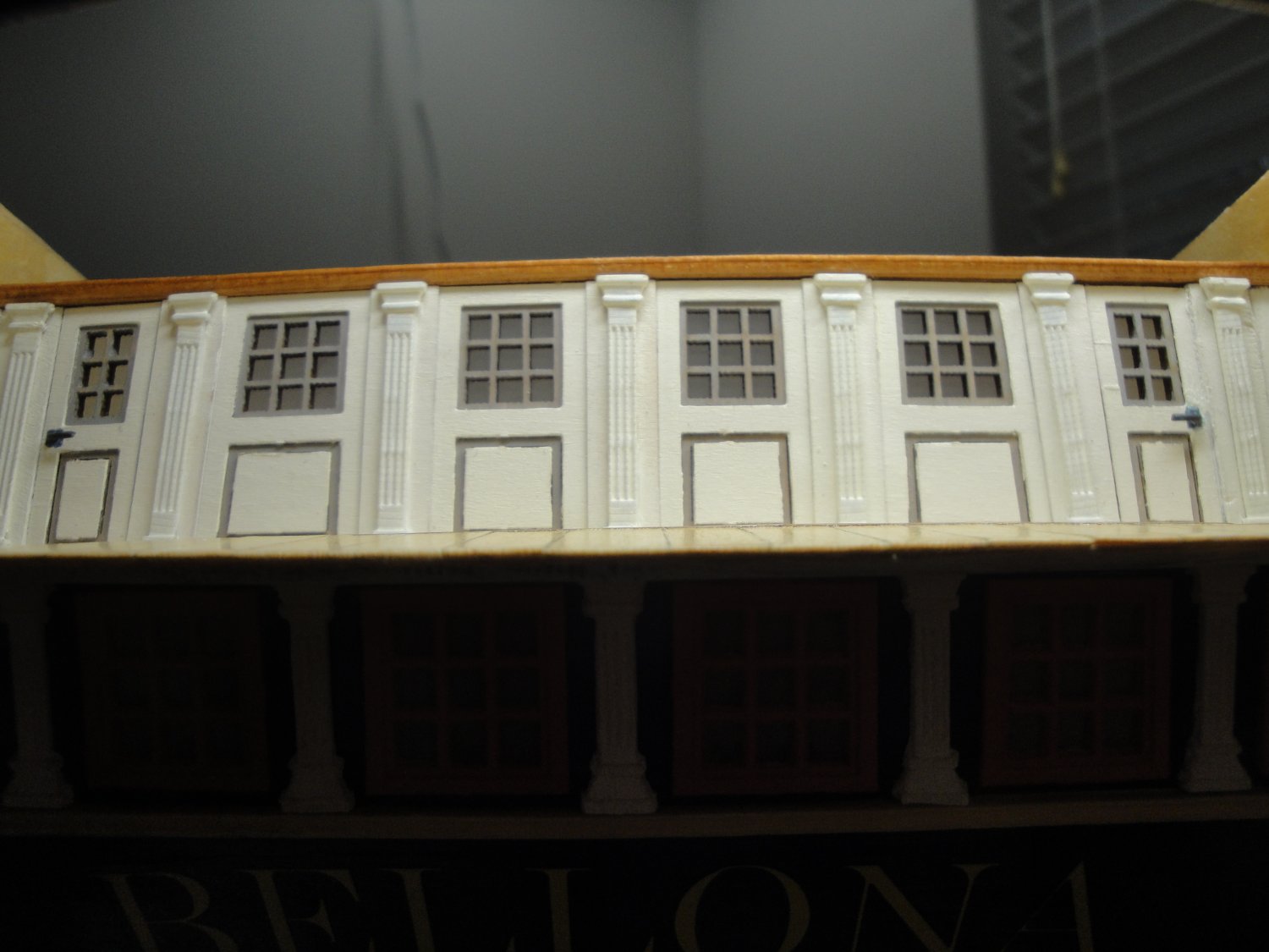
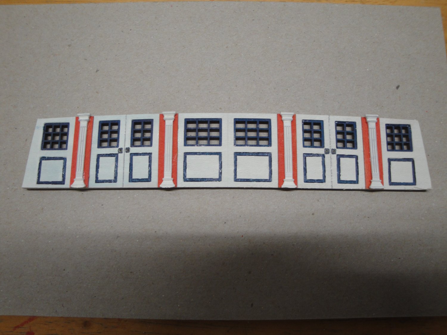
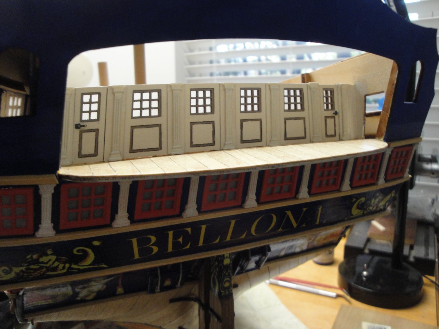
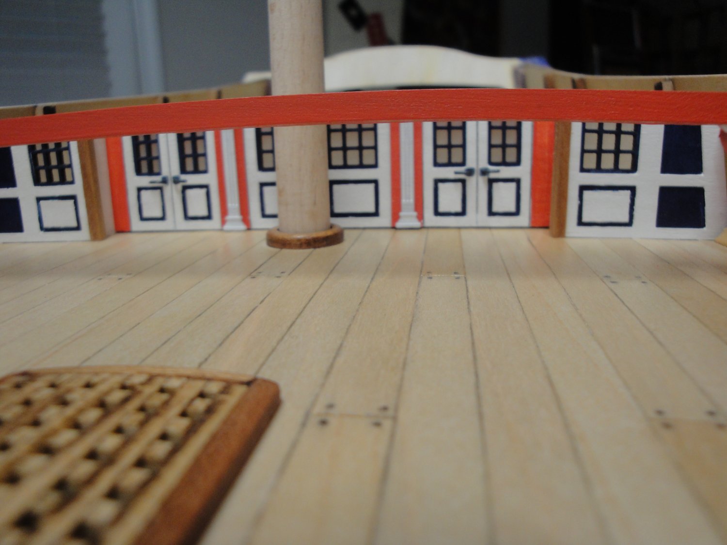
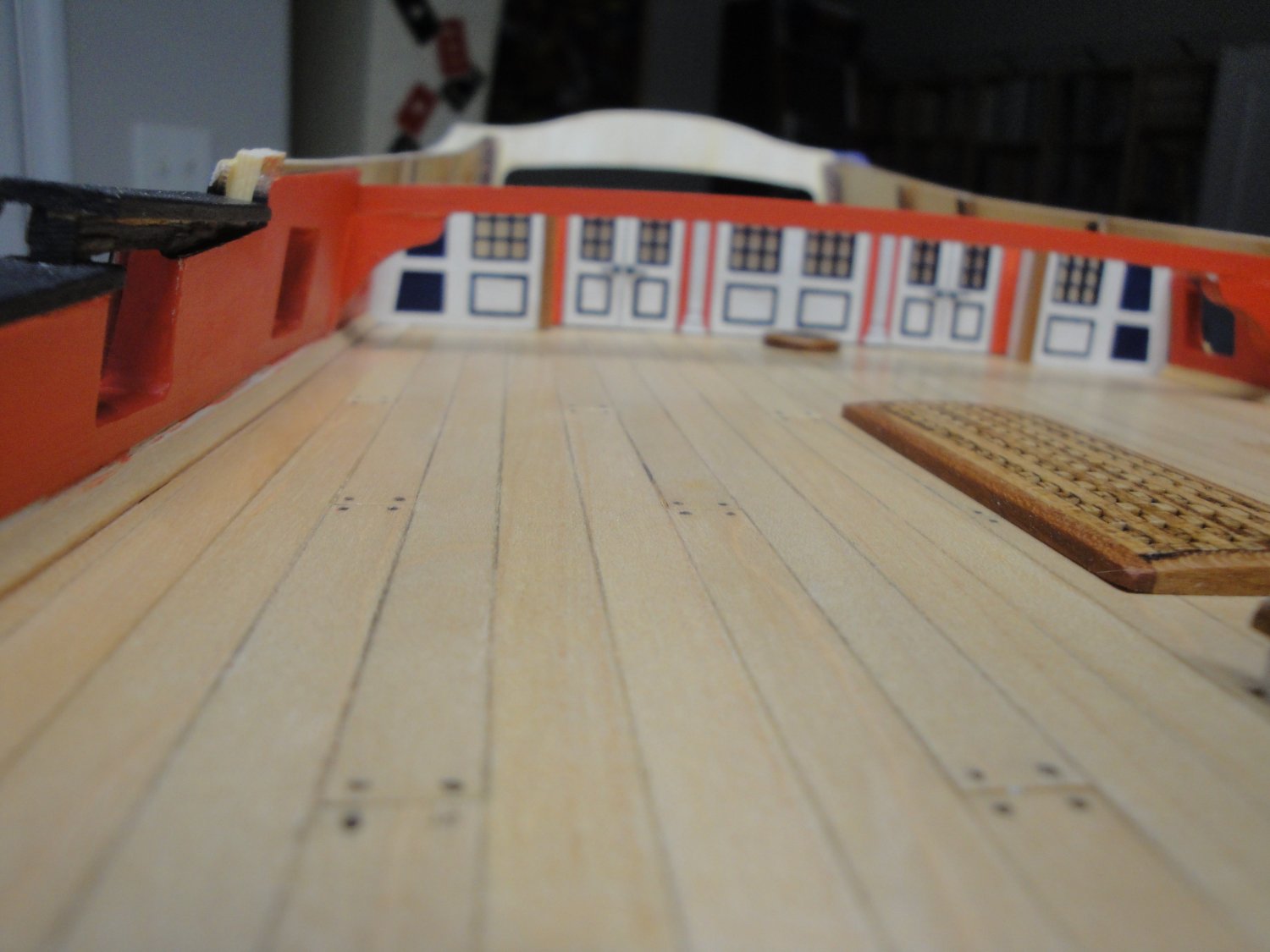
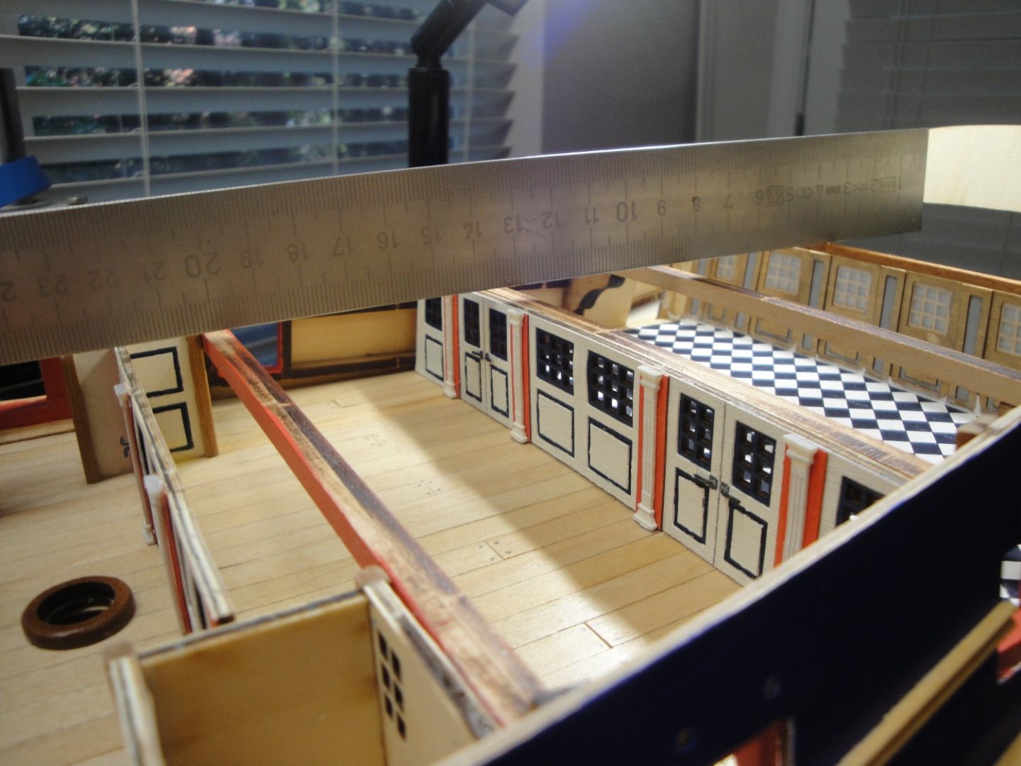
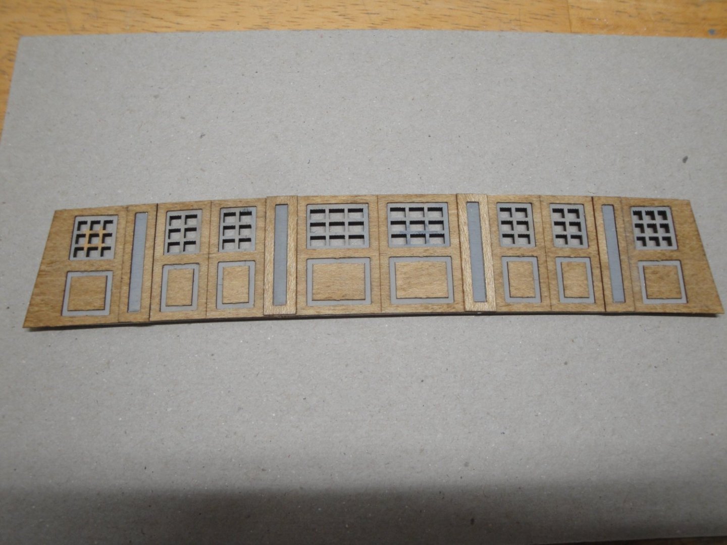
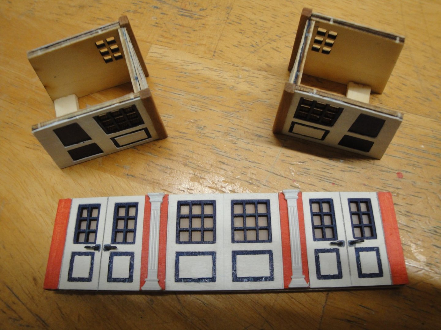
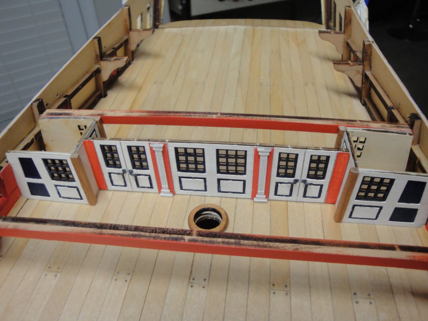
The next phase is the building of the screen bulkhead. Here I wanted to depict it as close as possible to the National Maritime Museum model, which is basically painted in white. I only used some light gray for the windows and the wainscoting of the panels. Inside. the wood is just stained, lightly: The white putty is used to provide a very tight seal between the bulkhead and the planking. This prevents the light to go through. The rear screen bulkhead is slightly convex in shape. Yves


- 507 replies
-
- 12
-
-
-
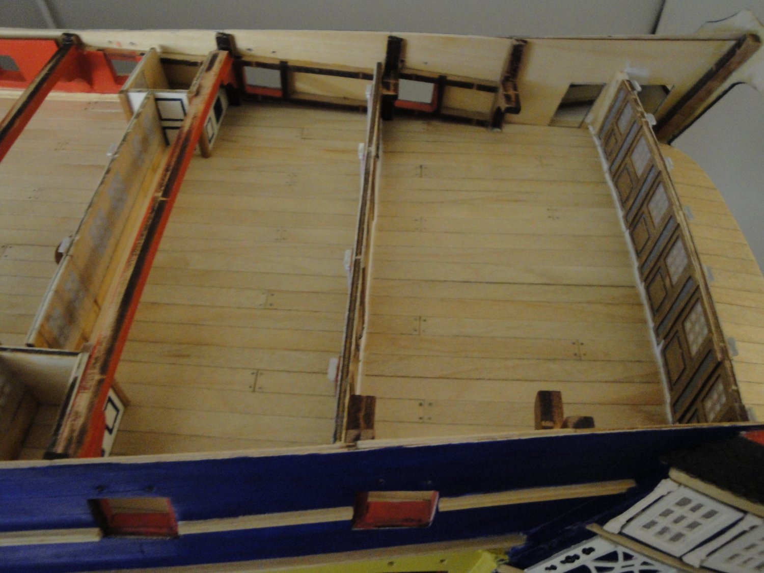
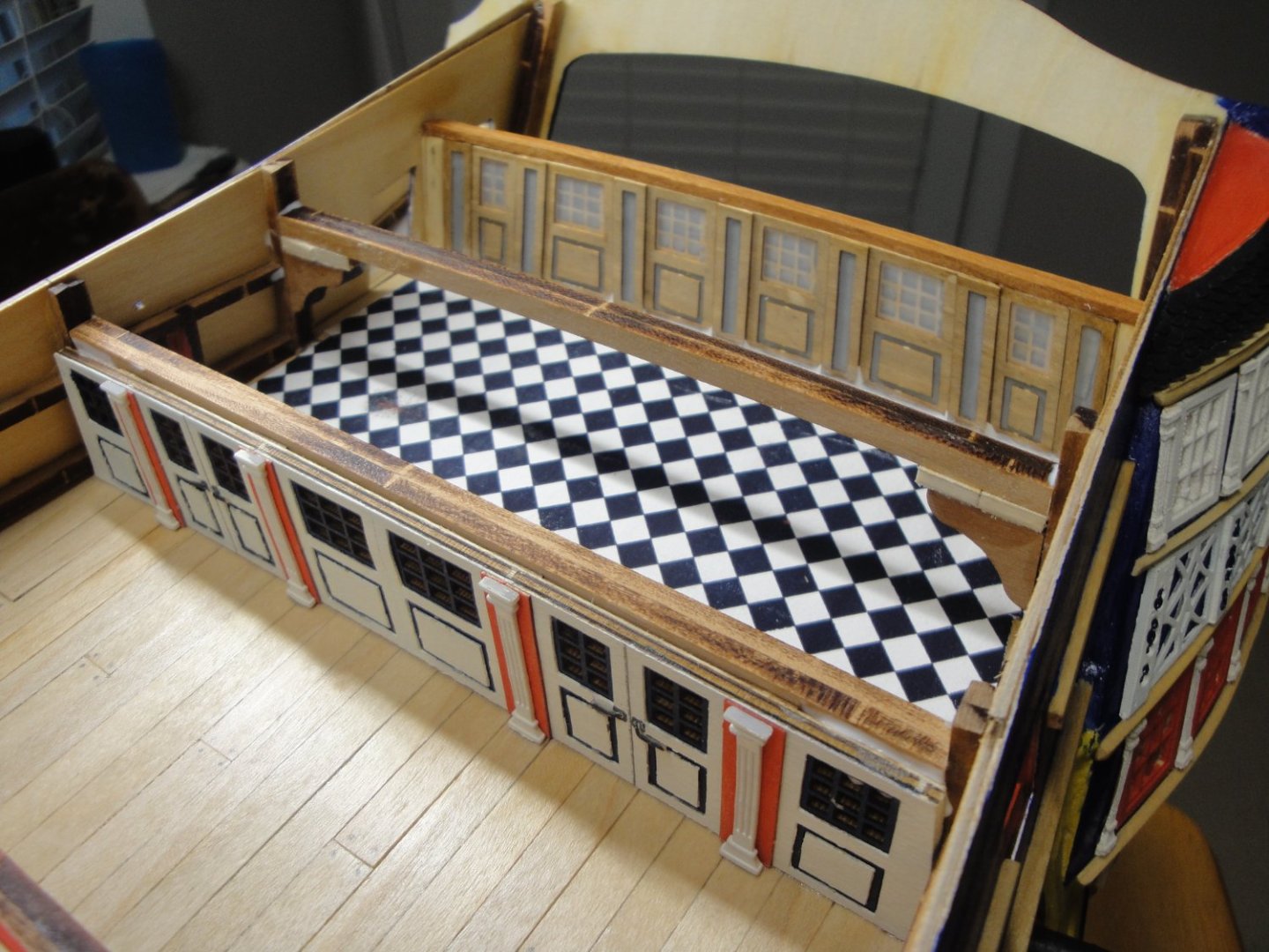
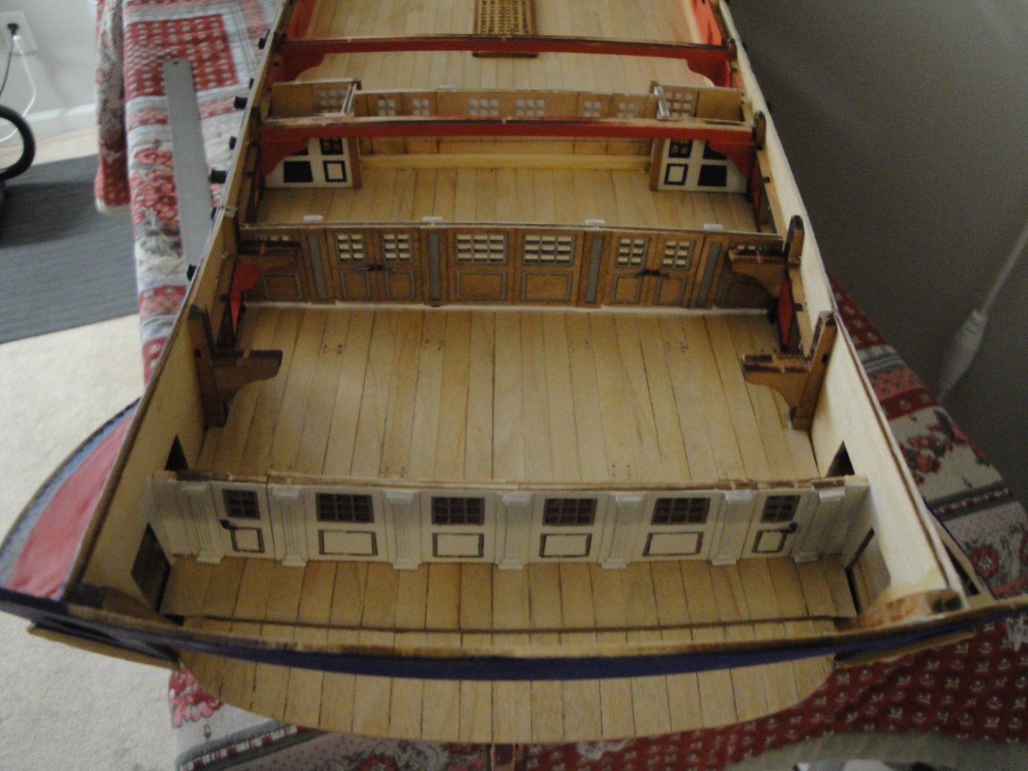
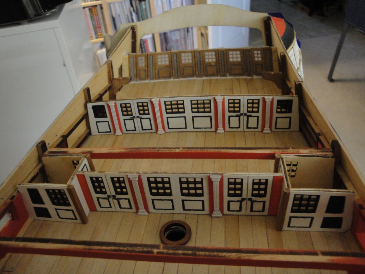
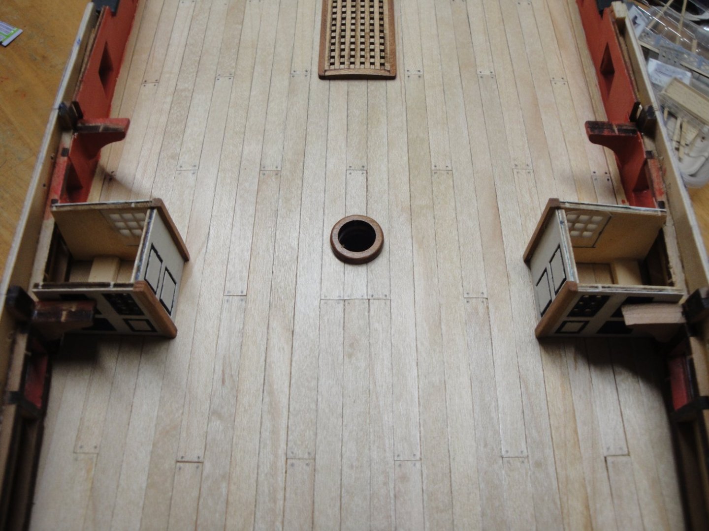
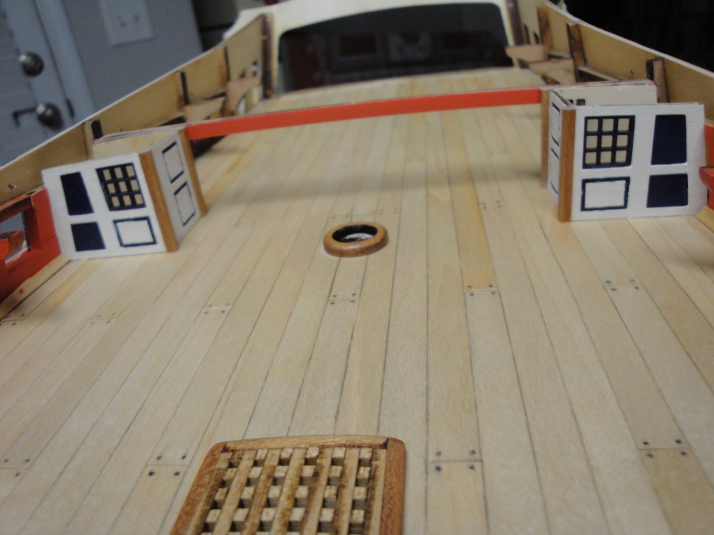
With such a large quarterdeck, it was necessary to build the various partitions and walls, offered by the kit. Once again, all of the things you are seeing will be occulted by a bare poop deck. It is kind of sad in a way. The bulkhead located right behind the wheels and mizzen mast: All the assemblies are part of Session #4. The balusters/columns are 3D resin printed. I have replaced the printed corners with 3x3 mm cherry wood pieces, as the corner balusters provided in the kit were not matching at all. The resin parts were way too large and did not fit the limited space between the two sides. Below, an overall view: Yves


- 507 replies
-
- 10
-
-
-
ZOUKEI-MURA....the ultimate kit. Yves
-
I like the contrast between the main stove and the polished copper lids. Yves
-
Is that a John Stobart fine print? It reminds me of his style. What a great picture !!! Yves
- 238 replies
-
- 1
-
-
- Robert E Lee
- steamboat
- (and 3 more)
-
The difference in size between Bismarck and Yamato is quite obvious on your picture. Yves
-
Big difference! It was worth redoing them with the U shaped strips and the brass wire. Yves
-
Fantastic. What a great model.... I wish you could also model a section of the Mississippi river.... to go with it. Yves
- 238 replies
-
- 2
-
-
- Robert E Lee
- steamboat
- (and 3 more)
-
Hmmm.... I want to see some grease spilled on the deck.... 🙂 Yves
- 27 replies
-
- 2
-
-

-
- galley stove
- Syren Ship Model Company
- (and 1 more)