HOLIDAY DONATION DRIVE - SUPPORT MSW - DO YOUR PART TO KEEP THIS GREAT FORUM GOING! (Only 36 donations so far out of 49,000 members - C'mon guys!)
×


SJSoane
-
Posts
1,649 -
Joined
-
Last visited
Content Type
Profiles
Forums
Gallery
Events
Everything posted by SJSoane
-
 hi druxey, That sounds like a great idea. I realize that I can paint the ends of the planks before installing, which should help with access to this difficult edge. And sanding sealer would be easy to apply at this point. What do you recommend for sanding sealer, with enamel paint coming over it? Mark
 -
Hi Jason, thanks so much. I see you did a very nice paint job on your HMS Snake; do you remember what paint you used, and how you did the edges of the planks? I am still open to ideas! Mark
-
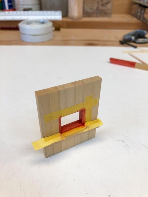
I discovered this morning that I had two old jars of Caboose Red, one was PolyScale acrylic, the other Floquil enamel. The PolyScale was too red, bu the Floquil was perfect. I tried 100% paint, and then diluted 50-50 with thinner. The diluted looked a little more like the stain, and this is what I tried on my mockup. But the paint ran a bit. I did manage to scrape and sand away the overflow, so it did not seem to get into the deeper grains as the stain does. So, I might be in business here. I may try undiluted paint, which I imagine will run less, but will be brighter next to the stain. Mark
-
ancre La Belle 1684 by Oliver1973 - 1/36
SJSoane replied to Oliver1973's topic in - Build logs for subjects built 1501 - 1750
Beautiful CAD drawings, and beautiful craftsmanship on the stem so far! Did you do the sketch drawing of the crew? Mark -
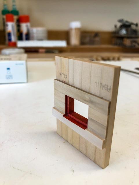
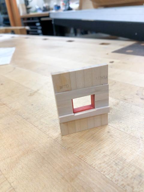
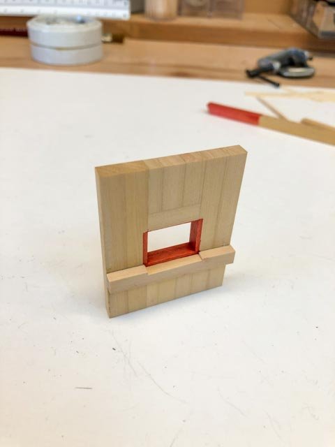
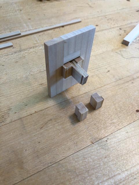
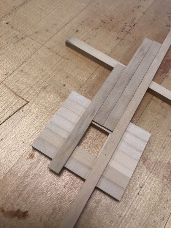
hi druxey, Yes, I will try that. It looks good! I had a good day building a mock up of the ports, testing some construction and painting ideas. I made a little jig, with rabbets the size of the port stop, for drawing the stop edge on the frames, then using them to scribe the edge of the plank, and finally to align the plank edges together when gluing. It keeps a very even margin around the port. I use wedges to hold them firmly in place. I then tried masking off the stop edges with Tamiya tape, and staining with my usual red stain. A little bit of creep into the grain, as expected. Then I planked up the sides and top, using the jig. I have also modeled the wale, in this mock up, because this will be the most complicated paint intersection I have to worry about. The wale is black on the face and tops and bottoms, except at the port cill where it is also painted red on top. I need to study how all of this will work cleanly. And tomorrow, I will try druxey's method of painting the Floquil Caboose Red on the edges of the planks. We will see.... Mark
-
Two steps forward, one back. I was ready to start planking today, then remembered that I need to resolve how to paint the red at the ports. The Admiralty Paints Red Ochre was way too orange to match the red on the Bellona second model. So am back to the idea that I can continue to stain red parts throughout the ship where I don't have to worry about creep along the grain; and then carefully paint the edge of the planking at the ports with acrylic paint to match the stain. I discovered that an old jar of Floquil Caboose Red is an almost perfect match to my stain, although obviously it is more opaque than the stain. But before trying this out on the hull itself, I have made a mock-up of a port, which I will use to test the stain + paint idea and see how it looks and works. I will also explore the idea of painting the edges of the planks just before I glue them in, saving problems with masking this thin edge. No wonder it takes me so long to move this model along... Mark
-
While installing the hawse lining/planking pieces, I had occasion to look at the dimensions of the hawse holes. Both Steel and the Shipbuilder's Repository call for 1'-5" diameter holes, "after the pipes are let out". And they call for hawse lead pipes 1 ½" and 1 ¾" thick respectively. I notice that the hawse holes in both the first and second contemporary models seem a smaller diameter than 1'-5". In the models below, the distance between the cheeks is 2'-3", and you can see in the finished model that the hawse holes are about half the distance, or about 13". And the models don't show the hawse pipes, only a clean hole drilled through the bolster and the lining. So, could the models be showing the actual diameter of the hole with the pipes installed but not indicated, which would be 1'-1" for Steel (1'-5" minus 3" lead pipe thickness)? Interesting that they don't show the hawse pipe exposed to the outside. Surely the lead would run all the way out over the bolster, if it were there to protect from wear. Mark
-
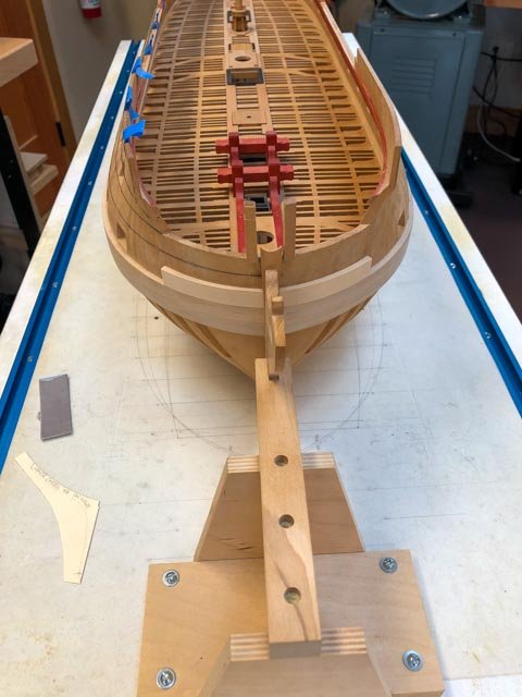
At last, sawdust created again. I decided on a modelmaking cheat at the bows. The actual construction has the black strake and all planking above running all the way into the rabbet at the stem. Later, a thin lining is added over this planking between the upper and lower cheeks, through which the hawse holes are eventually drilled. I decided to combine the planking and the hawse lining piece as one part, the thickness of the planking plus the lining. I would rather fit one piece to the bow, than one and then another on top of it. The black strake and one additional strake will butt into the aft end of this piece, and one will never see if they run under the lining or not. And instead of messing with the steamer for this short thick part--the two parts combined are as thick as the wales--I sawed these to the curve at the bow. A fun change from steaming. Only a few thin planks plus the thicker channel wales will remain to be bent around the bows. Mark
-
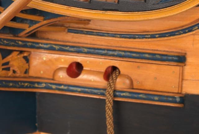
The contemporary model and paintings clearly show the pin racks on the shrouds. Interesting! Any ideas of what belays to these, since the main lines according to Lees for the 1742 HMS Medway do not belay to anything called a pin or pin rail. There are some lines, like the yard tackle falls, that belay to a shroud--I wonder if that means a pin rack on a shroud? Mark
-
Oh, good, thanks druxey. Nice to know you have seen this elsewhere, and it is not a contradiction between a Lavery drawing and the original Bellona sheer.
-
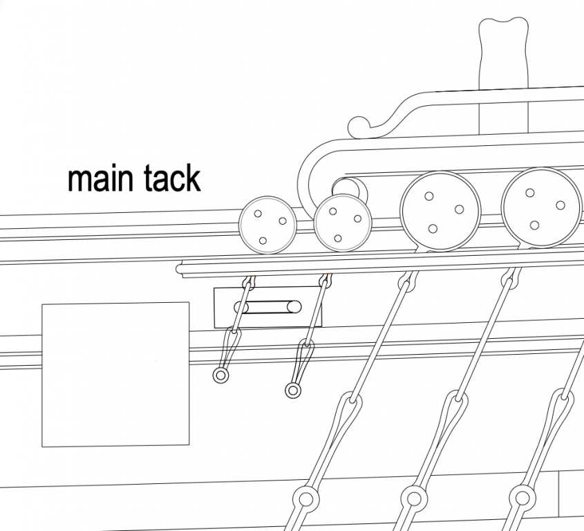
Here is another oopsie in the different Bellona drawings, where the sheave for the main tack appears to be hiding directly behind the chains and preventer plate/bolt for the foremast standing backstays. The original sheer from the shipwright does not show the sheave, while Brian Lavery shows a sheave in this location in the drawing on the inboard side of the bulwarks. Could the line from the main tack really sneak its way through this? Mark
-
Thanks, druxey, I will shift them up a little. It only needs to be a few inches. I also note that they are different lengths as they move astern. There is no rhyme or reason to this, except that they were trying to avoid collisions with other things. So there must have been a little flexibility in this. I'll bet when the draftsman was laying out the sheer and the preventer plates, he was not thinking too much about where the plank seams would land; assuming the shipwright would adjust accordingly when working on the actual ship. Mark
-
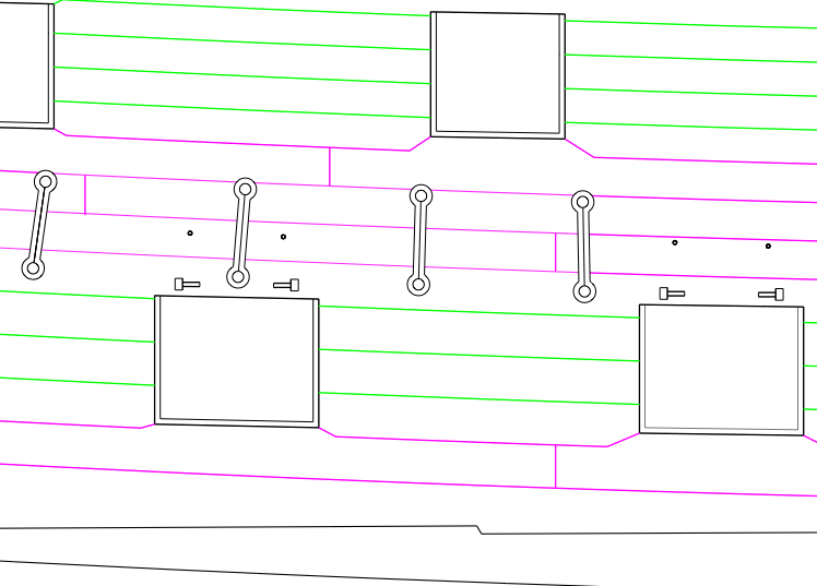
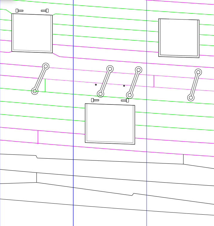
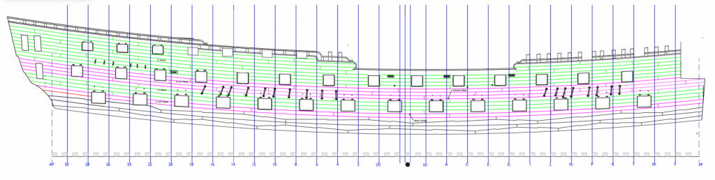
Hi druxey, yes, more jigsaw puzzle. The image with the blue station lines below shows port #11, and the small dots are the locations of the lid laniers. I eyeball measured the height of these above the gunport from a photo of HMS Victory, as a proportion of the height of the port. Although they fall very close to the seam of the channel wale, they clear the preventer plates. The image without the station lines shows ports around the main mast closer to the waist, and here we can see how the bolts at the tops of the preventer plates come very close to the seam of the channel wale. The wale is specified as three planks, and the wale and the preventer plates are located exactly as drawn in the original Bellona sheer; so as designed, the bolts fall in an unfortunate place. It is also interesting that the lower ends of the plate fall off the wale altogether. Since I am building it as designed, I guess I live with this. It will make an interesting talking point years from now... Mark, thanks for reminding me of the discussion about the port stops. I now remember being convinced by the argument, and intend to form the stops that way on the model. What is interesting about the Steel planking plan is that the plank edges at the bottom of the port show how they form the rabbet at the cill; but the planks at the sides come right up to the edge of the frame without forming a rabbet. I am guessing that this may have been drawn for convenience, and that they should have been shown stopping short. But what do I know?😊 Thanks, everyone, for continuing to critique my interpretations and drawings. This project gets significantly more accurate from your questions, comments and suggestions. Good thing I am retired and have time to go back and redo things. This process also points out the value of first drawing it as best one can, then getting comments on the drawing and adjusting accordingly. A temporary step backward, in order to jump forward! (and Landrotten Highlander, I looked up the Echternach, Luxemburgh dance on YouTube; at good metaphor!) Mark
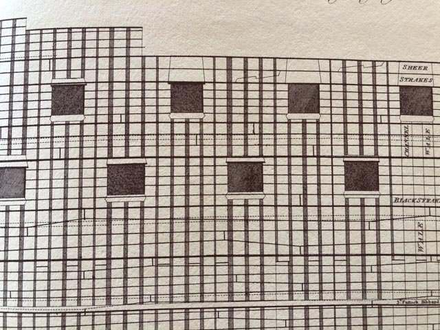
-
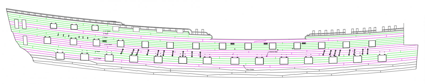
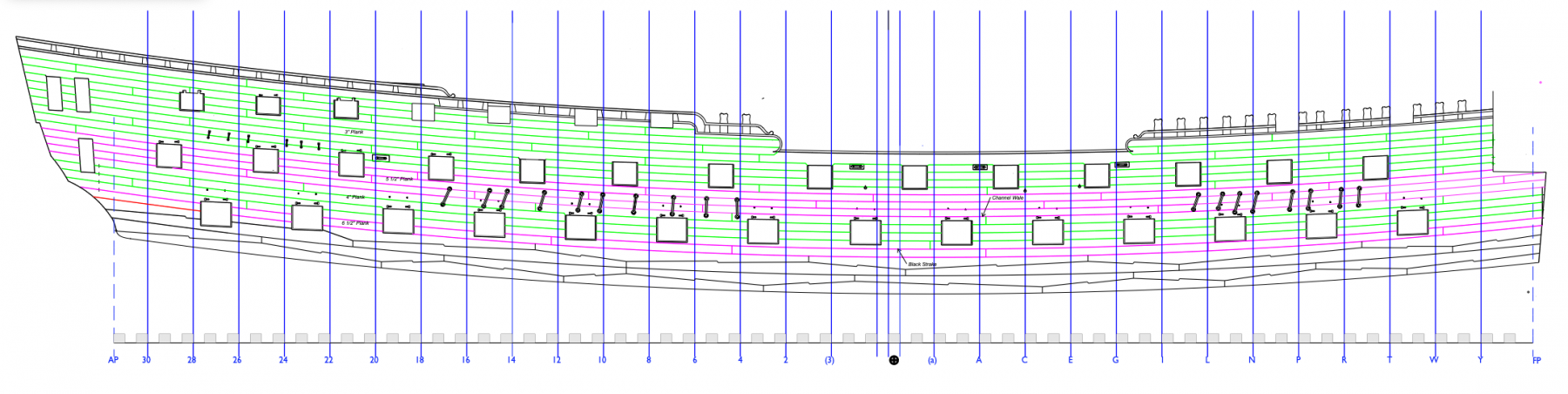
Looking at Steel's expanded planking plan really helped improve my plan. I discovered the following "rules" in his plan: 1) A butt can fall over the top of a port, if it is at least two planks away from the port 2) A butt can fall beside a port, if it is at least 2 feet away. 3) butts do not necessarily line up vertically; they shift from the normal spot if needed to follow the previous two rules 4) wood is "worked up or down" to a port if the line of the plank is within 8" of the port. 5) the black strake as well as the channel wale can be worked up or down. 6) planks can go as long as 32' if needed to meet the previous rules I also discovered the sheer strake, the one just below the planksheer at midships. It is not called out in the Lavery's Bellona drawings, but it shows in Steel and in David Antscherl's FFM Vol. II p. 21. This is an inch thicker than adjacent planks, and has a hook scarph at midships. I have highlighted it in orange in the drawing below. And I discovered that the planking when worked up or down, falls about 1 ½" below the cill of the port. This implies that the port stop is the cill itself, and the planking drops below it to form the rabbet for the port lid. But Steel's planking plan does not show the same rabbet at the sides. So maybe the port stops are added at the sides? And finally I discovered that the channel wales, if planked in three strakes as defined in most sources, causes the deadeye chain links bolts to fall on a planking seam. That doesn't make sense, but the original Bellona drawings clearly show these lining up one third of the way along the channel wale. Any thoughts about this? So, I present my planking plan, version 2, below. I believe it follows all of the rules for planking that I have discovered, except for the curiosity of the channel wale chain link bolts. Mark

-
When in doubt, look at the sources you already have... I just looked at Steel's Naval Architecture plates, and discovered the expanded planking plan. It is clear that the butts are not organized to align vertically on the hull; they bounce all over the place. And there are butts getting close to ports; I will measure to see what the tolerance was. So, a little redrawing is in order. Two steps forward, one step backward, two steps forward... Mark

-
Hi Mike, That is a good question, I have been pondering for some time. I originally developed the red stain because I liked the softer look than paint. But I did not think through things like how to color the ends of the planks at the ports. I have purchased the Admiralty Paints red, and I will see how close this matches the stain I have already applied to parts on the gundeck. Then I have a choice; I can try to tint the Admiralty paint to match the existing stain, and use it only where I have wicking problems. Or, I can switch over to paint altogether for the remainder of the ship, knowing that the red stain already applied on the gundeck pieces will be out of sight forever more, once the upper decks go in. Do I recall correctly that you are using Admiralty Paints on your Winchelsea? And are you hand painting or air brushing? Mark
-
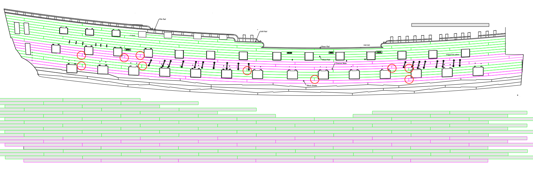
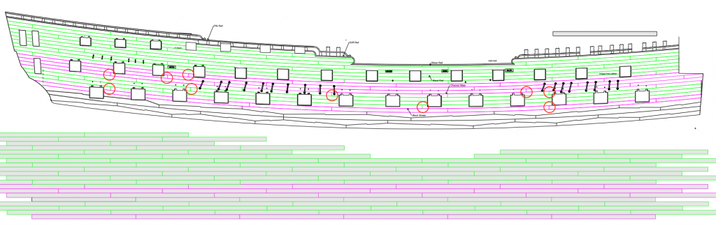
I forgot to mention in the previous post that the Bellona was an early experiment with a 74, and the gunport spacings are not as regular as later ships. The original drawings from NMM even have the gunports shown in a couple of different locations in different colors at the upper deck and quarterdeck towards the stern, as if they were experimenting with fitting everything together. I chose many years ago to place my ports according to the original Bellona model, which was perhaps the most awkward arrangement. The later Bellona model has them in slightly different locations. In either one, however, any regular butt spacing scheme is bound to crash into a port in one place or another. I have circled below some of the awkward butt ends. I wonder if I should give up on a regular pattern for butt spacing, and just move butts where needed to avoid ports? By the way, the red planks below are the channel wales and the black strake, both thicker planks than the green ones. Also, the pattern of the main wales reproduces the pattern seen on the original Bellona model. So this firmly locates butt ends that the black strake needs to avoid. Mark
-
Hi Landrotten Hghlander, yes, I will probably pre-paint on the frame itself, but the challenge comes in painting the ends of the planks where they land at the port. I am concerned that my stain will wick into the end grain and streak along the surface. My earlier experiments with staining in this area tended to do this. So I will need to use paint at this point, and work to match the color of the red stain elsewhere in the project. Hi druxey and Mark, this planking plan is a monumental jigsaw puzzle. I was not able to find a 74 gun planking plan on the NMM site (does anyone have a link to one?), and so I was left with trying to reconcile various rules for planking with the reality of where I found ports. Also, the extreme sheer of the planking relative to the ports on a 74 leaves places where the two geometries really clash, particularly aft of midships. Here are a couple of issues: Plank length I worked with planks of 27'-1", which was in the range of Goodwin's 25'-30' lengths, and allowed each end to land on the center of a frame. Also, it seemed to work with the spacing of the lowest gunports; a different length eventually creeped the butt ends into a gun port further down the hull. But this length eventually creeps into the gunports on the upper and quarter decks, since they are at a different spacing. Another option is to reduce the working lengths consistently at one point in the hull, keeping the butts aligned up the hull, but shifting the butts into a better spot. Has anyone seen this idea? Aligning the butt ends? I could solve some of the awkward butt ends by shifting the pattern to a different plank length higher up the hull. But all of the planking plans I have seen keep the butt ends aligned all the way up the hull. Maybe I should consider changing the lengths higher up? The butt ends won't even show under the frieze painting higher up. Giving wood to the ports I did give wood to the ports in a number of places, but the ones left unfixed are where the black strake would have to be pulled up to the lower edge of the port. I could not see this done in any photos of contemporary models. Maybe the black strake does pull up, but is dubbed down to match the thickness of the planks above the black strake at these points. This would appear to keep the black strake's upper surface as a smooth, uninterrupted curve. And it would provide a few more breaks in the planks above, reducing some of the butts needed further along the hull when I run out of the 27'- 1" length limit. Little puzzles like this sure make one appreciate the ship builder's art! Mark
-
Thanks so much, Marc, I am a little surprised how much I did not draw when I did my original drawings so many years ago. There is a lot I have learned since then, and a lot I didn't know I needed to know! Mark
-
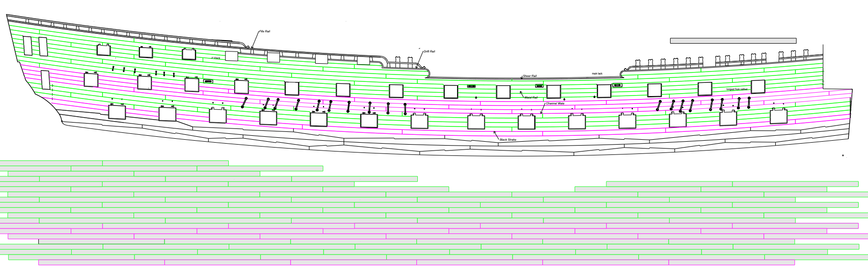
It took me a few days to draw the planking plan. I had some difficulty seeing how planking pattern would fit onto the actual sides and interact with the various gunports, so I drew the pattern itself below the ship sides, and then projected a line up to find the appropriate place for the butts (see below). On a few butts needed to be shifted from the pattern, to avoid falling directly above or below a port. I am really appreciating my decision many years ago to do an Admiralty framing system; no planks to worry about below the main wales! I did confirm that all of the gunports have stops, whether carrying a gunport lid or not. I could see this in photos of the 2nd Bellona model, and also in Rob Napier's Legacy of a Ship Model: Examining HMS Princess Royal 1773. I don't know why they would do this, except to provide opportunities to install gunport lids later. But I cannot imagine why they would ever do this. So, another mystery from the 18th century. I have to do some experiments with how I will paint the red around the gunports. I am concerned about my red stain leeching into the ends of the planks, and am considering airbrushing the Admiralty Paints red into the edges. But how this works with my existing red stain is still to be seen... Mark

-
Phil, The sails really add to the overall character of the model. Nicely done! Mark
- 355 replies
-
- 2
-

-
- prince de neufchatel
- schooner
- (and 3 more)
-
Mike, as I contemplate planking my Bellona, I came back to your site for inspiration--you have done a beautiful job so far. I do have a couple of questions. How did you cut the ends of the planks so precisely at the ports, with an even reveal for the gunport stops? Did you draw the reveal on the frame, or use a temporary stop block in the port itself? And how did you color the joints between the planks? I am not a fan of strongly contrasting joints, and I like the subtlety of yours. I have had some success with using dark titebond glue elsewhere in my build, but would be interested in how you are doing your's. Mark
- 607 replies
-
- 4
-
-
- winchelsea
- Syren Ship Model Company
- (and 1 more)
-
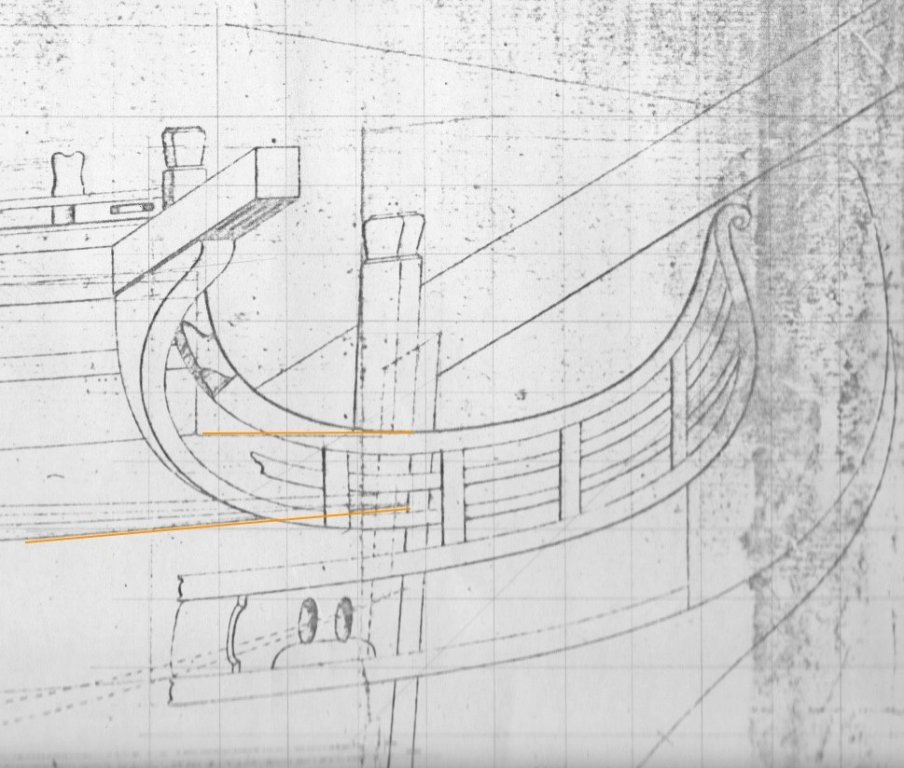
Thanks, druxey. And thanks for checking, always appreciated! In this case, the string at the bow where it hits the rabbet is at the height as shown on the draught. There is an interesting visual anomaly here. The upper edge of the bow is trimmed to match the sheer of the small platform, which is parallel to the sheer of the upper deck. And since the sheer of the outer planking is more sloped than the deck, there is a little wedge of planking between the two that does not fair with the outer planking (see below). This little anomaly will likely not show, since the headwork will later mostly cover this up. But as I look at the string again, it looks like it does need to pull up a bit between where it hits the rabbet, and where it begins to go around the bow. It does dip a little between the two data points. After sleeping on this, it occurs to me that I might as well start planking from the wales up, rather than planking the channel wale and then going back to plank in between. Starting at the wale gives me a definite edge against which to start spiling the upper planks. And as long as the channel wale is clearly lined off with the string, it should remain as accurate a placement as it would have been starting at its lower string anyway. Mark
-
Hi druxey, So as I walk around the model, trying to visualize how I start the lower strake, I see that the thread will not be a very firm edge against to start spiling planks. Would I now make a card template cut to the string line, with which I can then use to shape and test the lower edge of the actual wood plank? I would think this will be particularly needed for the first planks which will have to be steamed around the bows. Mark
-
I tried druxey's idea of string glued to the line. It is definitely easier than clamping a batten, and easier to see. the bow definitely fairs more easily. I am not quite sure how easy it will be to fit the individual strakes to this string; it was very comforting to sit the strake on the batten as I fitted its edge. Mark