SJSoane
-
Posts
1,655 -
Joined
-
Last visited
Content Type
Profiles
Forums
Gallery
Events
Everything posted by SJSoane
-
 Hi everyone, Unfortunately, the train left the station quite a long time ago, when I purchased the thread for the Bellona--some Gutermann 50, and a variety of DMC Cordonnet sizes--all in Ecru color. I don't fancy throwing it away and buying again. So I will have to learn how to color what I have. After a few more experiments, I am quite sure that the RIT dye in the required 140 degree water, has affected the cotton thread. A rope that is tightly wrapped and stable lengthwise before going into the dye, becomes stretchy after soaking in the hot dye--even after only three minutes. This lets go the tension holding the rope together. So hot water is out of the question for me. Other option to explore, after casting around this site and the internet: Walnut stain mentioned above: I looked up the link, and the product is no longer available. Minwax stain, fruitwood for running and jacobean for standing. I will try this, but read concerns about an oil based stain causing problems when using glue on rigging. Anyone have experience with this? General waterbased dye stain. Chuck used this some time ago in experiments. Does anyone have suggestions for which colors will work? Transtint analine dyes. I am using these for the very nice red in my hull, mixed into a polyurethane sealer. But I don't see subtle enough colors for rigging in the color chart. Does anyone have suggestions for colors here? Richard's reference to Rob Napier's use of a product from Pro Chemical and Dye. I have his book on the Princess Royal--a terrific book--and I will pick up a copy of the one on the Valkenisse. As long as I am retired and in no rush, I might as well explore this whole question of coloring rope. I have found it to be an elusive topic so far! Best wishes, Mark
 -
Hi Gaetan, The rope is five threads each on 3 hooks, and holds together when I remove it from the ropewalk. It just starts to unravel after sitting in the hot water required for the RIT dye. I will look into the walnut shell ideas. druxey, if only I had known I could buy the Gutermann in a color that would work....oh, well, the price of learning! Mark
-
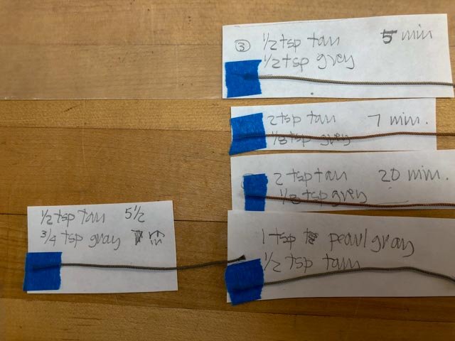
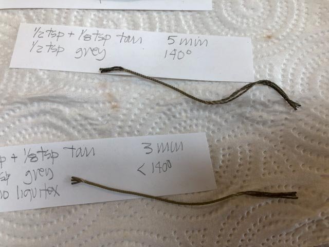
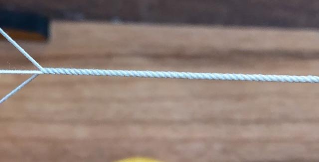
Hi everyone, After taking time off to build some garden trellises, I got back to work on the Bellona. And now the cannon are cast, I turned back to the ropemaking. Here is some 7" circumference breech rope (.035" diameter at 3/16" scale), made with 5 threads on three hooks, using Chuck's great Syren ropewalk. I am getting the hang of this now; I was under-turning before, worried about breakage. But I really cranked it up at both ends, and it came out well. I also solved the problem of getting the tension the same on all hooks, by using a small clamp to hold the 5 threads together at a hook at the same tension as the others, then tying off before removing the clamp. Pretty reliable method now. The next step is more problematical, dying the rope. I have been using RIT dyes, and started with a formula posted by Bob Westcott, based on N. Roger Cole's article on Alert Provenance and Construction. These turned out to be way too intense and too yellow for my Gutermann 50 cotton thread. So I started experimenting with difference mixes of RIT tan and pearl grey, and at different intensities and times (see experiments below). I am finding this to be unreliable. The same mix and time gives different results when I try to reproduce it. On an earlier test, the hot water needed for the RIT dye suddenly made my rope stretchy. When I turned up a really tight rope for the next effort, it actually began unraveling in the hot water, as seen below. So I am not so enthusiastic about RIT dye, right now. Does anyone have experience with wood stains as a colorant? Would these be damaging to the cotton over time? I will keep experimenting! Mark

-
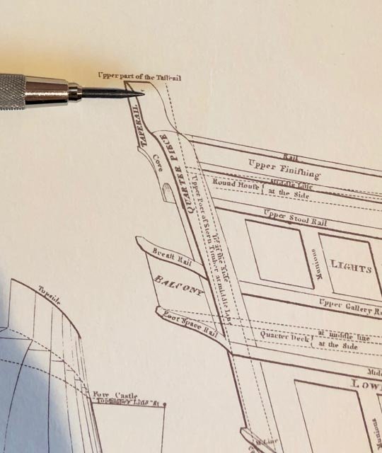
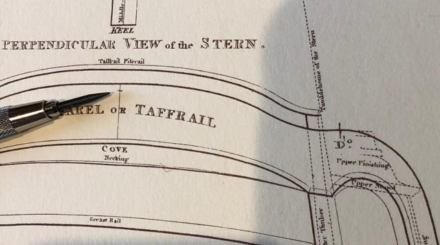
Hi Gary, I looked up Steel's dimension from top of keel to top of taffrail for an 80 gun ship, which is 53'-4". I then measured 53'-4" against the drawing of the 80 gun ship in the folio of drawings. It comes up to the pencil mark pointed to by the pencil below. It looks 5" short. And then I measured up the same point in the view of the stern, and it also comes up 5" short of the top of the taffrail. But this stern drawing also clearly shows that the open railing on top of the taffrail is above this 53'-4" dimension figure given by Steel. So it answers one question; is the railing within or above the given dimension--it is above. But it doesn't answer why the given dimension in the tables does not match the actual dimension in the drawing. Maybe the 5" shortage is to the top of the rough framing, whereas what we are seeing in the drawing includes a railing installed on top of the rough framing, but below the uppermost open railing. I hope that makes sense! Best wishes, Mark
-
Hi Gary, I just saw your post. I will look in a couple of places and see what I come up with. Interesting question! Mark
-
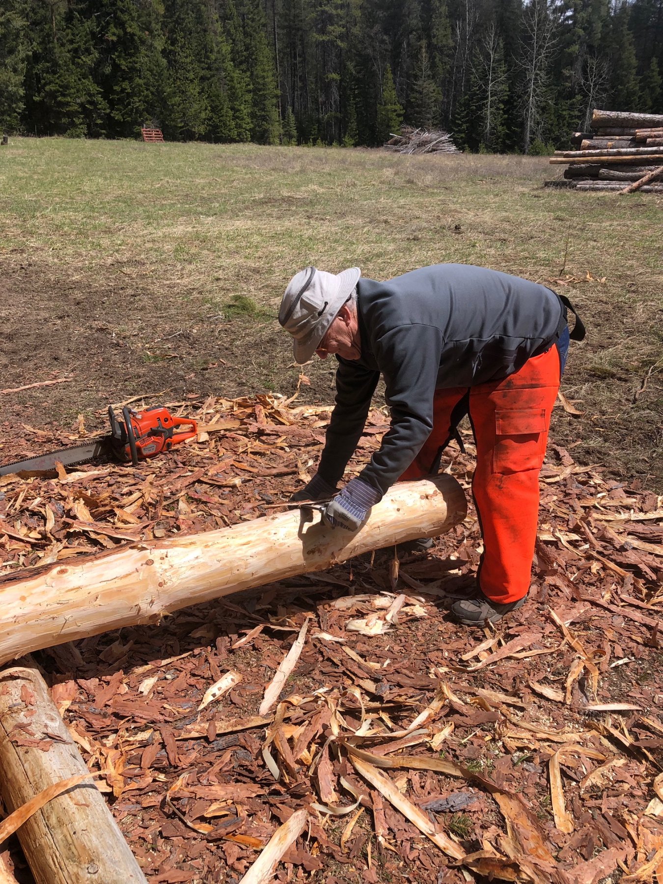
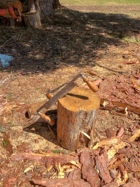
Hi Marc, We stripped 144 linear feet of 12" diameter logs--I did half--and I discovered muscles today that I did not even know existed. This is definitely a young person's sport! Mark
-
I took some time off from the ship after competing the cannon to help a neighbor get some logs for a dock project nearby. I learned how to use a draw knife for stripping the bark. This gave me a great sense of the woodsmen who found and prepared the trees for ship construction. I can hardly imagine what it would be like to do this all day, every day, for your entire working life. I borrowed the orange kevlar chaps, which helped avoid knife cuts to the shins. They are also supposed to prevent cuts from chainsaws, but I didn't test them for effectiveness. Now if I could only find some boxwood trees in this Rocky Mountain softwood forest....😀 Mark

-
Marc, the weathered wood looks great. Those are artist's colors? Mark
- 2,699 replies
-
- 6
-

-
- heller
- soleil royal
- (and 9 more)
-
druxey, Greg and Mark, thank you so much for your kind comments. Even more importantly, thank you for your continued support and advice as I undertook this challenging new task. You and many other members of Model Ship World helped me through some very complex processes. I am not entirely sure that I would have persevered if I had not obtained such good advice at difficult moments. And it is very satisfying to obtain new skills, perhaps one of the biggest driving forces for me in building this ship model. I am sorry I failed at creating the King's cyphers, but Chuck saved the day for me with his excellent laser cut examples, made to measure. I am looking forward to working in wood again, but remind myself that my skills at the start of learning miniature woodworking were as non-existent as my skills at the start of learning to cast metal. One just has to jump in, expect mistakes and mis-steps, get good advice from all of you, be willing to throw away poor efforts, and just keep on going. As Gaetan said when I initially feared cutting deck mortises by hand, do something enough times and you will get very good at it. Having said this, I doubt I will be casting 74 cannon again in my lifetime! Mark
-
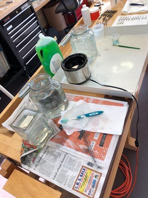
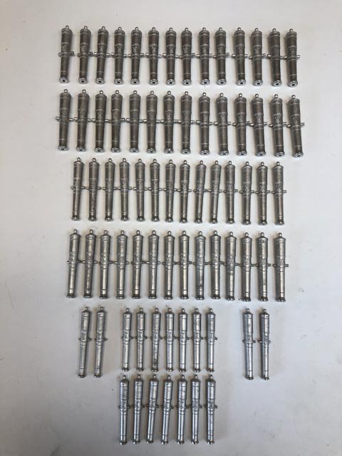
Thanks, Mark, I followed your process, substituting only the pickle solution that I got from Otto Frei. It was quite an elaborate setup on the workbench, with the dawn soap, then rinse, then pickle and its rinse. I used a toothbrush to scrub with the dawn soap: The Jax Pewter Black worked perfectly, even though it was a few years old. I tried a few ways of applying it. First, I put the cannon in a 50/50 solution of Jax chemicals and water, and let soak. It was a terrible outcome, turning a rusty brown. Then I tried applying 100% Jax with a rag, which got a good color, but was a mess after a while. So then I settled on a small paint brush applying the Jax directly. This worked really well, because I could work on a few places taking the color less than others. And it kept the mess to a minimum, with only a small amount of Jax in a little plastic cup. After the Jax dried, it was a little rough and dull. So I tried steel wool afterwards, as suggested by Jax. This really buffed it up, but took too much color out. So then I just buffed the cannon with a small cloth. It gave a very nice luster, and left the color. And the entire set is DONE. All they need is a ship now.... Mark
-
Beautiful detail and construction, Gaetan! Mark
-
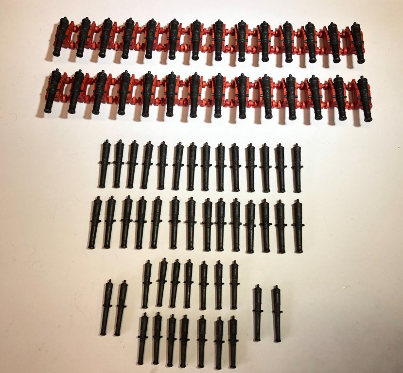
Finally, the cannon are finished except for the blackening. That was five months, off and on, making these cannon. When they are all laid out in one spot, that is a lot of firepower! Tomorrow, I will try the blackening with Jax's Pewter Black. It is a few years old, but I don't see an expiration date. So I will try and see. I will also try cleaning them with Frei Otto's Pickle, which I got as part of a package of jewelry supplies. It is supposed to clean up and brighten for soldering, so perhaps this will help with the adherence of the blackening. Jax also recommends cleaning with dish soap right before blackening. Does anyone have experience or advice using this pickle, or any other advice on getting good outcomes with the blackening? Mark
-
I fully confess to OCD on this, I am trying to get help for it... A small reason for this is that I got involved a number of years ago in studying the classical language of architecture, which also used a proportional system for defining the proportions of everything in a building, from the largest shape down to the smallest moulding profiles. I found it to be a fascinating exercise, compared to today's "I feel like it looks good". So, I have been interested in the parallels between buildings and ships designed according to proportional systems, and wondered if the same reasoning held true in both. I think I have discovered that the ships were a lot more flexible in this regard. Fun exercise; now I will follow Steel's table wherever it might lead me! And druxey, surely there never would have been a conversation as you described, in the entire history of ships...😀 Mark
-
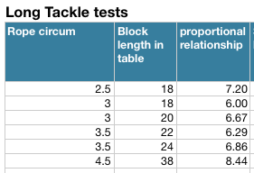
OK, I admit I am getting obsessive about this, but I looked at Steel's table more carefully, and discovered that there is no consistent proportion of rope to long tackle block size. See below the 6 different long tackle blocks in Steel's table. The 18" block reeves both 2 ½" and 3" circumference ropes, while a 3" rope reeves through both an 18" and a 20" block, and a 3 ½" rope reeves through both a 22" and a 24" block. And while there is a rough proportion of 6 to 6.86 times the circumference of the rope to the block length, the outliers at the small and large end are both a larger proportion than the middle range. In other words, there is no rational and consistent proportion between rope and block length, according to anyone's proportional systems! Now it could be that the ship did not want to stock too many sizes, and some served equally well for slightly different ropes. Although why the same sized rope could use two different block sizes is anyone's guess. Assuming these were not typos in the tables, and these were the real reality of the ship's blocks, then I am inclined to follow the tables rather than calculate to an unrealistic and inaccurate precision that did not really exist. There had to be a reason for this irrationality that I can no longer fathom, and now my head hurts from trying! Best wishes, Mark
-
Alan, fascinating! Mark
-
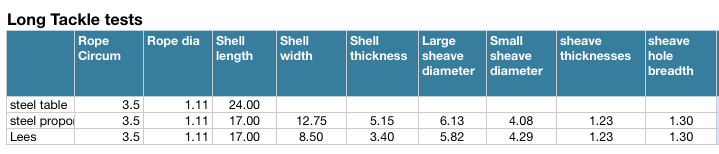
Switching back to the block sizes for a minute, I used a spreadsheet to calculate the block sizes according to Steel's directions, and compared the results to the blocks in his table. I did modify this somewhat, when I realized that a calculation based on the circumference of the rope would usually create a block with an inch and fraction length; but the lengths were always even integers. So I rounded up to the next full inch size. This brought the calculated blocks closer to the ones listed in the tables, usually within an inch or two although still smaller. The biggest discrepancy concerned the long-tackle or fiddle blocks. As seen below, I looked at the spritsail halyard, which according to the table is a 3 ½" circumference rope, with a 24" long tackle block. But using Steel's own formulas, the block would be only 17" long. He describes this block following all of the rules for a single block, only ⅔ times longer, and with the lower part of the block including the second sheave as ⅔ less than the upper part of the block. Lees' Masting and Rigging used different formulas that still arrived at a 17" long block. His formulas give a somewhat thinner and narrower block given the same length. And he give no sources for this formula. (p. 166) 17" is a long way from 24", we don't need Alan and druxey's calipers to see this difference. But I have found no other sources that could resolve this discrepancy. I suppose I could work backwards from 24" to determine what the proportions would be for all of the other parts relative to a 3 ½" circumference rope. Presumably, this would create a top sheave larger in diameter than would be required for a single block running the same circumference rope. Maybe the lower sheave should be the size for the single, and the upper 5/3 bigger? Who to trust? Mark
-
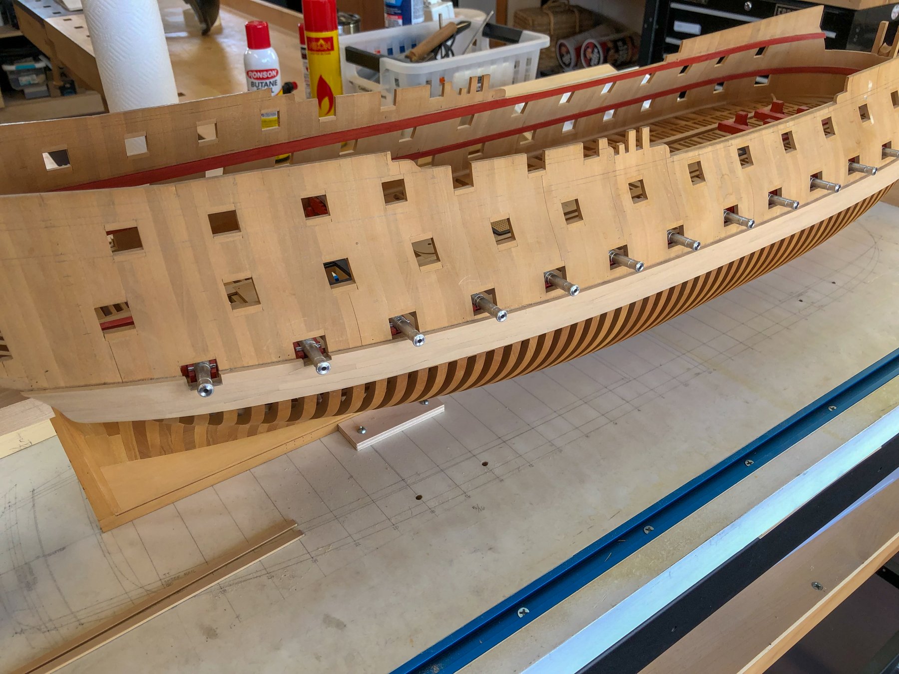
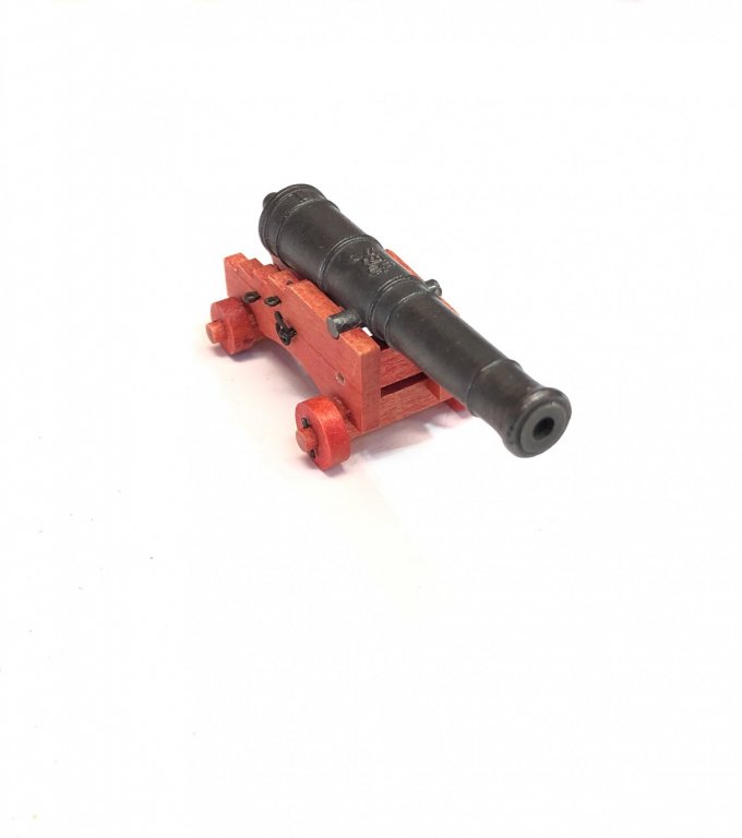
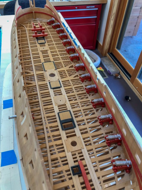
After a long few days, I have only the 9# guns left to drill. Just 18 to go! Just for fun, I put the 32# into their carriages and into the starboard ports. They are a little low because the deck is not yet in, but it gives a good sense of what the gundeck must have been like. And how awful it would have been to see that ship approaching you with guns run out and a hostile intent! Mark

-
Alan, you are right, we seem to have an irresistible desire to get it "exactly right", even though the difference is imperceptible--until druxey gets his calipers out, of course. It is like wanting to solve a math or engineering problem, where there is a great feeling that one has found the right answer, not an almost answer. But what a crazy attitude to bring to this hobby, where everything is approximate. Oh, well! It still amazes me to see how much full size boat construction is done by eye, not by precise measurements. There is a lesson here! Mark
-
Thanks, druxey, I am glad I didn't overlook something. You and Alan are probably on the right line of thinking that this has to do with the dates. The Bellona was built in 1760, 30 years before Steel's tables or formulas. Since everything grew as the century wore on, I would think the Bellona's sizes would be at the smaller end of possibilities, likely smaller than in the tables at the end of the century. So I will likely stick with the formulas, assuming this was an earlier tradition passed down to Steel even as the blocks were being made larger in practice, as reflected in his tables. Oh, boy, more fun with a spreadsheet... Mark
-
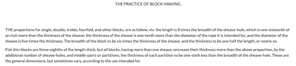
Hi druxey, I got them from: https://www.hnsa.org/manuals-documents/age-of-sail/the-elements-and-practice-of-rigging-and-seamanship/block-making-vol-i/ and these are repeated in David Antscherl's Fully Framed Model Vol. IV p. 63. They also can be found in Lees' Masting and Rigging, p. 164, but there are some discrepancies in this source relative to the other two. Lees, for example, has the sheave diameter as 4 times the width of the sheave, but the other two are five times. Also, Lees has the width of the sheave hole as a sixteenth more than the sheave, but the other two have it as 1/16" larger. Mark

-
This is a very interesting way of turning small, thin pieces. I have not seen this before. Very clever! Mark
- 306 replies
-
- 13
-
-
- schooner
- la jacinthe
- (and 1 more)
-
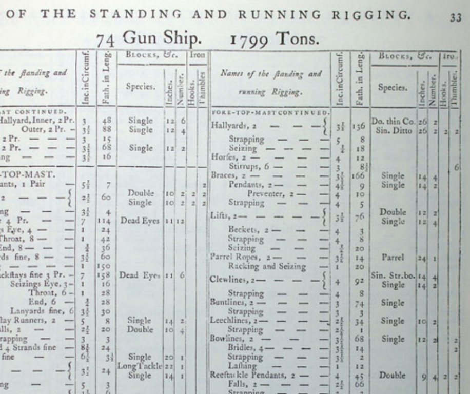
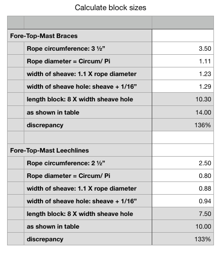
Thanks, druxey and Marc, for your thoughts on boring cannon. I do remember the advice I got from Gaetan years ago about how one's skills and speed increase through repetition. This is proving to be very true. However, taking a break from drilling cannon, I started looking again at the rigging for the cannon. I dug out my old spreadsheets, and noticed for the first time a big discrepancy in Steel's tables for sizing rigging and blocks. What he says about the sizes of blocks does not correspond to the blocks listed in his master table, a reproduction of which can be seen here: https://maritime.org/doc/steel/tables/pages/032-ShipOf74Guns.htm So here is what I found. Look at the table: Look at these examples to explore: Fore-Top-Mast Braces rope circumference: 3 ½" Single Block length: 14" Fore-Top-Mast Leechlines rope circumference: 2 ½" Single Block length: 10" But when we follow his instruction on sizing blocks (see spreadsheet below), this is what we find: The Fore-Top-Mast Braces single block should be 10.3" long The Fore-Top-Mast Leechlines single block should be 7 1/2" long This isn't just a little off, it is off by over 30%. Every block in the table appears to be larger than what his proportional rules would specify. Am I misunderstanding something here? And if not, should I be following his table, or following his calculations? Best wishes, Mark
-
Alan, I just discovered the other day--after suffering from the same problem--that you can drag photos directly into the text box where you want them, rather than dragging them into the attachment box at the bottom. They still show up in the attachment box, but they stay in the right order in the text box. I am not sure of the effect of holy water as well.... Mark
-
Beautiful, crisp, craftsmanship! Mark
- 607 replies
-
- 6
-
-
- winchelsea
- Syren Ship Model Company
- (and 1 more)
-
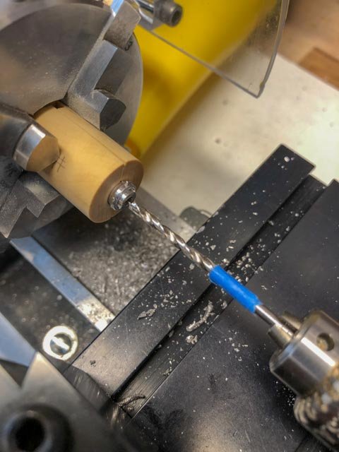
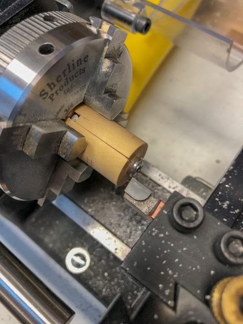
Here is the sequence I am going through for facing and boring the muzzles. First, the barrel is put in the centering jig: Then the jig is mounted in the 4 jaw chuck, using the drill chuck in the tailstock to grip the cylinder at the front of the barrel, to ensure it is centered before tightening up the 4-jaw chuck: Then the cut-off tool is run up against the long cylinder cast at the front of the cannon, to true it up. I do this turning the chuck by hand. I also true up the outermost edge of the swell of the barrel, also turning the chuck by hand. The pewter is really easy to trim: I cut off the excess, using a hand saw: Then, I center drill and drill the bore: Next, to keep the foremost moulding the same thickness, I run the cutter up against a .10" feeler gauge, and set the digital readout to 0". Back up the cutter, face the barrel down until I hit 0" on the digital readout. This trims up the face so the moulding is exactly .10" wide. Done. Next. Only 60 to go....