SJSoane
-
Posts
1,650 -
Joined
-
Last visited
Content Type
Profiles
Forums
Gallery
Events
Everything posted by SJSoane
-
 Thanks, everyone. Here is the largest image my iphone will take. Above this, I need to switch to the DSLR. Mark
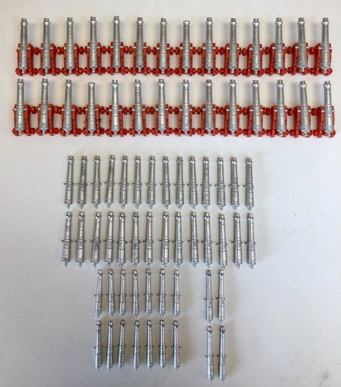
-
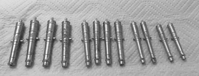
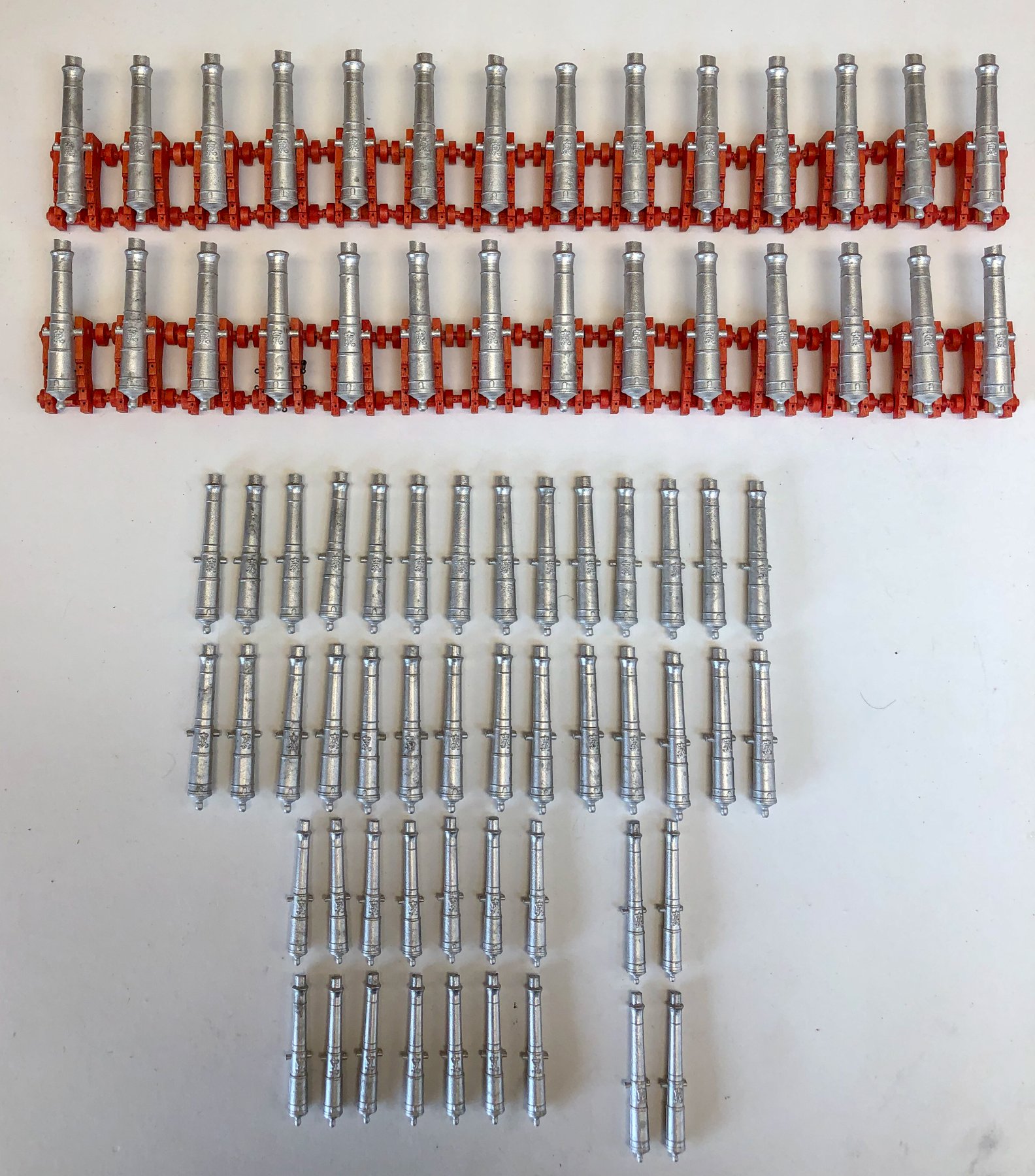
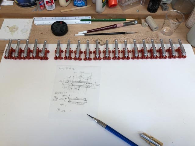
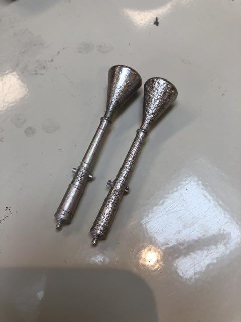
The cannon are all cast! It is fascinating to see all of the cannon together. 74 guns provides a lot of firepower, when you see them all in one place. And I am glad at this point that I did not build a first rate ship with 100+ guns. This got very weary after a while. Next, cleaning up with files, facing and boring the muzzles. And then messing with blacking. A big step completed! Mark
-
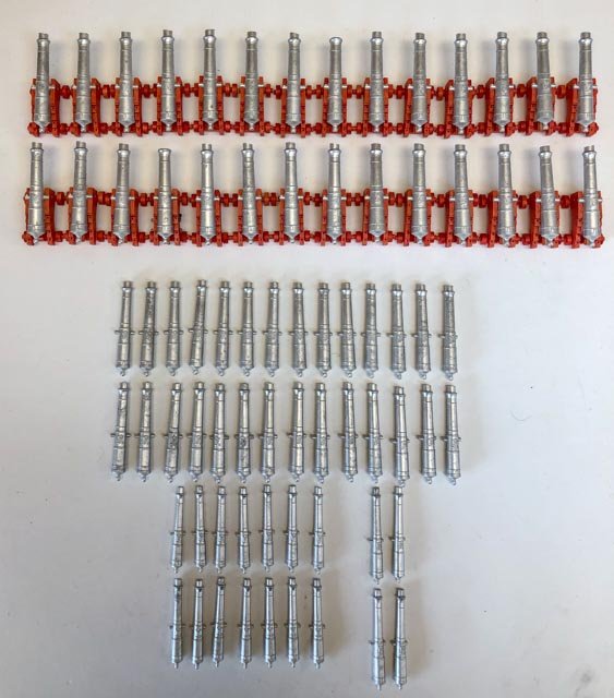
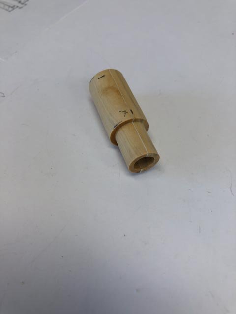
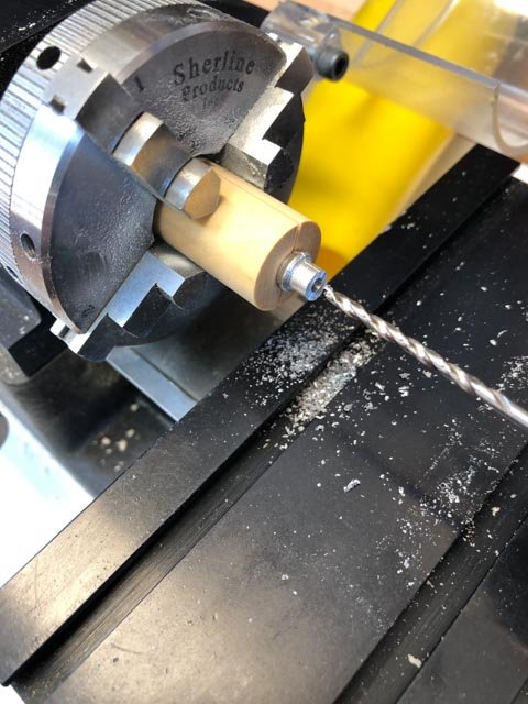
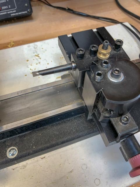
Hi everyone, More casting, I have only 11 of the 32# and 9 of the 18# to go. The 9# in long and short are done. I couldn't be patient enough to wait until all were cast, to see how they look lined up in the 32# carriages: However, I got up this morning to cast the final cannon, and my MicroMark butane burner died. It won't start. The sparker still works, and trying to fill it quickly has the butane coming out at the nozzle, so I assume it is full. There are no instructions for cleaning, so I appear to be dead in the water. I will have to buy another one, or figure out how to melt the pewter another way. I have a stand-up micro butane torch for soldering, but the heat point is too fine to heat up the entire ladle of pewter. So, moving on for a moment, I made the fixture for the 18# cannon, for facing and boring the muzzle. Much cleaner this time, now you helped me with the boring tool. Worked perfectly. This time, I glued thickish paper between two halves of the blanks, so I could easily split these apart when finished turning.
-
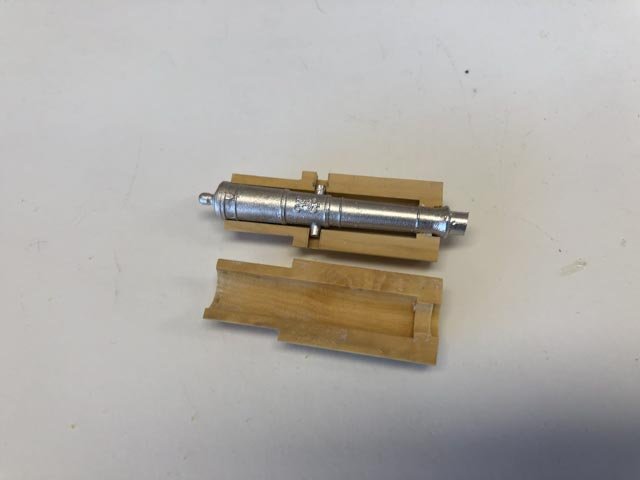
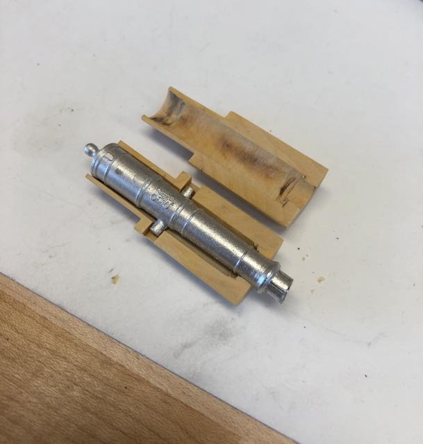
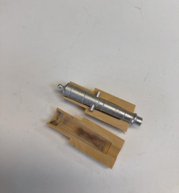
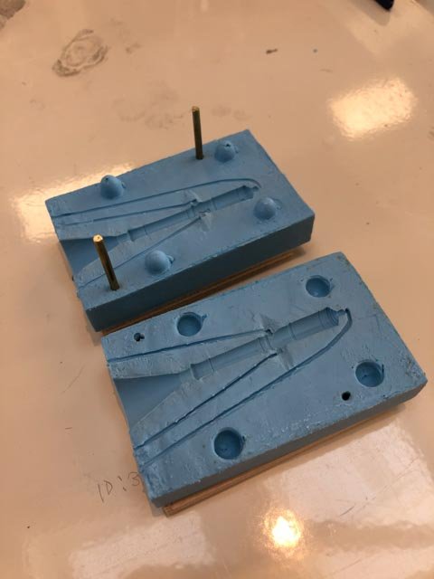
Thanks, Gaetan, it worked perfectly! So here is the fixture for drilling and facing the 32# cannon. This one is a little ragged inside because of my boring challenges. Now I have that figured out, the 18# and 9# fixtures ought to come out a little more elegantly. This one needed a little adjustment internally with a flexible shaft cutter. Mark
-
Thank you Mark, Landrotten Highlander, and Gaetan, for these ideas. And Gaetan, I look with envy at your full size lathe. I will likely never be able to get one, but I can admire from afar! I woke up in the middle of night, thinking that I should try cutting on the side of the hole towards the operator, rather than away from the operator as I tried yesterday. But that rubbed even worse. As it turned out, you were all correct. I rotated the cutting edge 90 degrees, and it works perfectly cutting on the side of the hole closest to the operator. Thanks! So it is interesting why the Sherline setup has a flat cut on the top of the boring bar for the set screw, when the bar needs to be 90 degrees to this arrangement. I then realized that they originally sold these for a boring head for the mill, which does use the flat to locate the bar correctly. They say that the bars can be used in the lathe, but as far as I can find, Sherline did not explain to rotate the bar in the lathe setup. There is an interesting lesson here. I knew something wasn't working well yesterday with chattering and burning, but I just kept on going thinking that I might be able to correct with a different feed speed or RPM adjustment. I did not take the time to rethink why this setup was not working well, or try other things like rotating the head. I know that machines speak to you, if only you are willing to listen. I did not listen well yesterday! Thanks again, everyone, Mark
-
Hi druxey, Good question, I could not find any instructions on the Sherline pages, except to line up the notch in the top of the boring bar itself, with the top set screw in the boring mount. But it sure does act like it is rubbing. The cutting edge as I have it set up appears to be meaning to cut at the back lower edge of the relief hole, cutting as the wood is starting to climb up around and back to the front. I also experimented with the angle of the boring bar to the axis of the lathe, because sometimes the bar started to rub at the outer edge of the hole as it got deeper. Didn't seem to make any difference to the quality of the cut. Maybe I should try flipping it upside down, although the flat would not align with the set screw. Mark
-
Looking great Michael. And I thought I was the only one who played with wind up rubber band planes. Never could get them to work very well. Mark
-
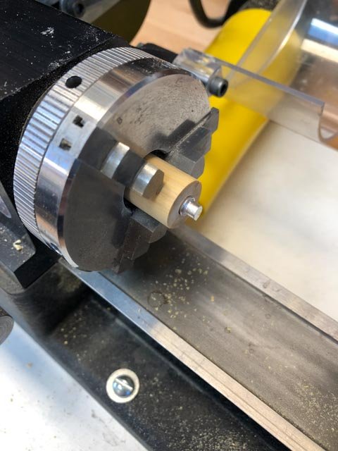
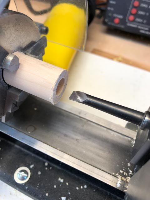
Thanks, Michael, you and druxey gave me good advice on this. I admit to being happier working with wood than plaster, though....😀 I spent the day building a fixture for the 32# guns, in order to mount the casts in the lathe for drilling and facing the muzzles. These are shaped so the hind end can go into the Sherline lathe headstock as far as possible, so the fore end does not project too far beyond the jaws of the chuck. This is to keep everything as concentric as possible at the face. Things get tight at the rear of the headstock, due to the Morse taper there. There will obviously be more clearance with the smaller guns. These still have to be drilled so the trunnions can recess into the fixture. You will see some burning on the inside of the fixtures. This is because I had to make very precise diameter holes to grab the front and rear of the cannon, and these dimensions were not an exact size of drill. So I used the Sherline boring tools in the lathe (see below). I could not get these to work very well. They cut grooves, and burned the boxwood I am using for the fixture (so the chuck jaws don't compress these too much, and throw things out of true). And I was taking such light cuts that it took a long, long time to bore out from the closest drill size I had first used for initial clearance. Does anyone have any thoughts about what I am doing wrong with the boring tool? This is the first time I have used them, so I haven't yet seen them work well. Mark
-
Hi vossiewulf, yes, that was my understanding. I wasn't sure just how much a difference it would make until I tried the experiment. Its value is now very obvious to me! Mark
-
Hi Ed, I realized after I posted this that I have asked you for what could be an entire book on this topic! Maybe you want to add some of your reflections into your latest volume? Mark
- 3,618 replies
-
- 3
-

-
- young america
- clipper
- (and 1 more)
-
Hi Ed, what a joy to see and learn from this project. As you worked on the rigging, did you see any general organizing principles for rigging that had evolved over time, like what is typically inboard or outboard of each other, why some lines led to tops and others to the shrouds, etc.? You have done such a great job in the past of explaining the logic of framing as you studied it; I wonder if there are similar lessons after looking at the rigging? An inspiration! Mark
- 3,618 replies
-
- 6
-
-
- young america
- clipper
- (and 1 more)
-
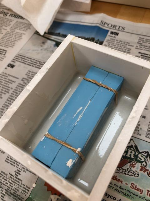
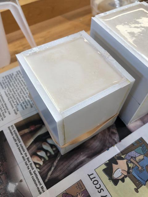
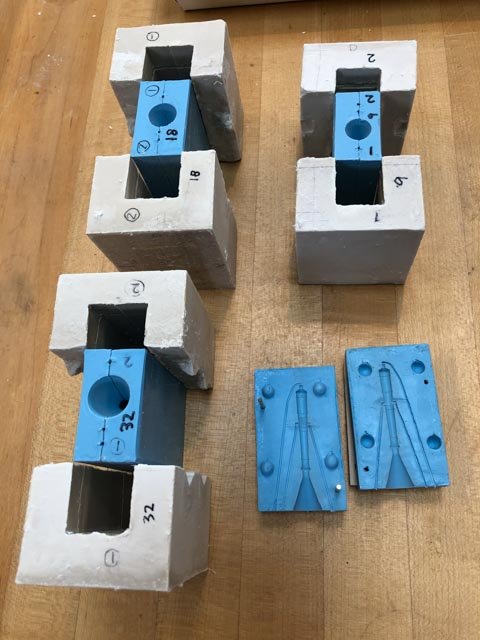
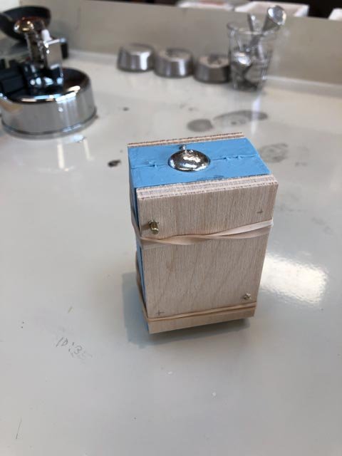
Hi everyone, I have been working my way through a number of issues fixing the cannon moulds. Following druxey's and Michael's good advice, I have cast plaster sleeves for three of the four masters. I used Hydrostone dental plaster, which worked very differently from plaster of paris. It is a much smoother finish, but it was exceptionally liquid following the recommended mix on the package, of 2:1 plaster to water. I found a manufacturer sheet online which suggested 3:1 plaster to water. I tried this for the second pours and it was better, but still very liquid. The watery mix began to attack the foamcore mould boxes. They are still moist and cold after sitting a day. I will wait until they are bone dry before trying. If I did this again, which I hope I will not have to do, I might try as much as 4:1. But for the 9" long gun, which was not having registration issues as much as the others, I tried drilling for registration pins through the plywood and rubber sandwich on a drill press in two corners. This seemed to work quite well. And just for fun, I tried pouring with and without first dusting talcum powder into the mould. You can see the fundamental value of the powder (talcum pour on the left, no talcum on the right.) The one on the right goes back into the melting pot. Mark
-
Thanks, Siggi, the weight of evidence seems to be pointing in the direction of laying them over the button. Since there is no other evidence we have been able to find for the period of ca. 1760 that is contrary to this, I will go with this solution. Plus, it saves making cut splices in 74 ropes! I am working away on plaster sleeves for my cannon moulds, hope to have something to show in a day or so. Mark
-
Alan, I found the Steel tables online: you can see the pages for a 74, and the jib info at: https://maritime.org/doc/steel/tables/pages/031-ShipOf74Guns.htm Mark
-
Alan, I found in Steele that the jib outhauler is 4.0" circumference or 1.27" diameter for a 74 gun ship (I find my notes, but I can't find again the original online...) Probably close enough to 1" at scale. Mark
-
Last time, I built a foamcore box, lifted the rubber mould half-way up off the base by two cardboard legs, and then poured liquid plaster halfway up. The cardboard legs were then encased in the plaster. I then flipped and poured the other half. It worked great the first time a few years ago, but failed in my recent effort when the plaster set too fast to pour. So if I can only get wall repair plaster locally, it would work better to build it up like a broken bone cast, with soaked cheese cloth? I assume this is so I don't have to worry about it getting too thick too quickly to pour. Mark
-
hi everyone, Alan, thanks for the image. It seems that there are three likely ways in which the breech rope deals with the button on the cascable; the one you have shown, the idea of a cut splice, and the one Siggi showed in the cross section model with it simply lying over the top. Once I start installing the cannon, I think I will make a final decision about which looks the best or makes the most sense. I can see the value of the plaster jacket now. As the moulds break in, they do not register as precisely as when they were new. I once used Hydrocal art plaster a few years ago and it worked well for this. But when I tried it again recently, it was very lumpy and it set up before I could pour. So I threw that away. My choices are more limited in my new little town, primarily plaster of paris for fixing drywall patches. Is there a reason why I need to order dental plaster for this jacket? Does the hardness matter? Mark
-
Ah, druxey, I see that now. My failed plaster pointed me in another direction, but I may be back to this if I cannot get the pin idea to work. Mark
-
Thanks, LH, this make sense. It sounds like you have a wealth of experience in this fascinating technology! Mark
-
Hi LH, a quick question. Do I assume correctly that the pins should be as close as possible to the cannon shape in the mould? I have a feeling that the rubber stretches a tiny bit across its width, and so it wants to be anchored as close to the cannon shape as possible. Or is it normal practice to keep these pins at the outer edge of the mould box itself? I suppose the only danger is getting too close to the cannon shape, and risking a tear. Mark
-
LH, that is a very good idea. I could clamp the master in the mould to position each side to the other, and drill through both. I'll try it on a reject mould and see how that works. Thanks! Mark
-
Nice problem solving, Alan. Mark
-
Not much new to report; starting to work my way through 74. I have noticed, though, that I am sometimes having trouble with the registration of the two halves, leading to mal-formed cannon. The rubber moulds are no longer as sticky as they were when new. I think this allows them to slide around a little relative to each other. I have to be very careful to ensure that the mould sides are aligned when clamping them between the pieces of wood with rubber bands. We will see if the 32# and the 24# moulds are durable enough to cast 28 good cannon each... Mark