SJSoane
-
Posts
1,655 -
Joined
-
Last visited
Content Type
Profiles
Forums
Gallery
Events
Everything posted by SJSoane
-
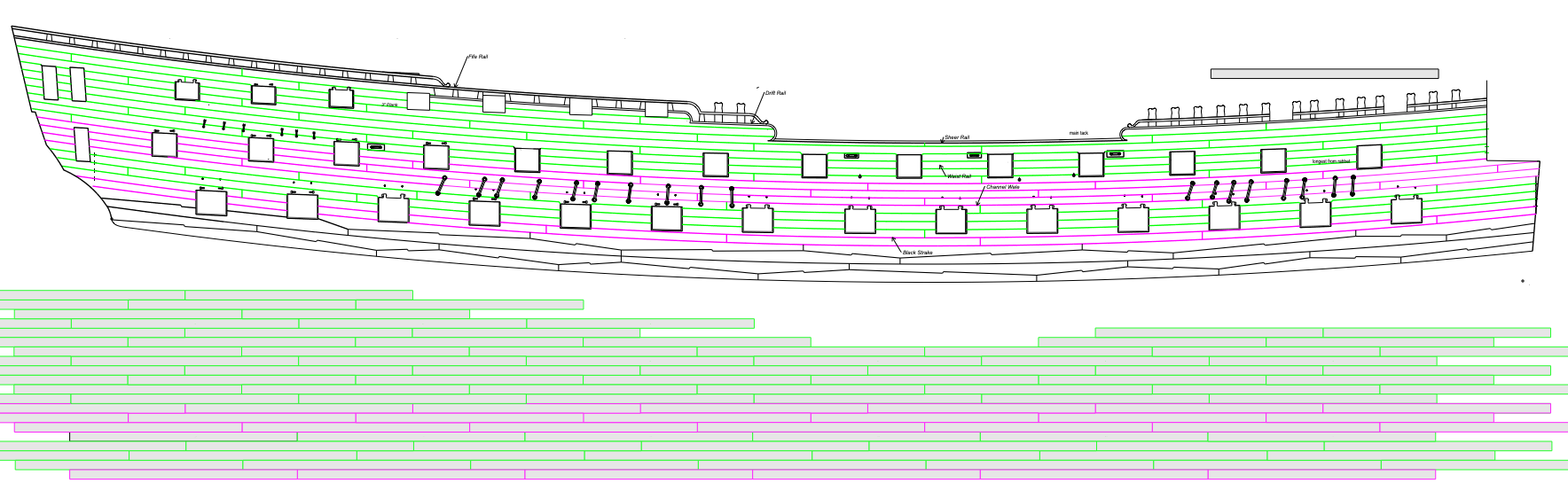
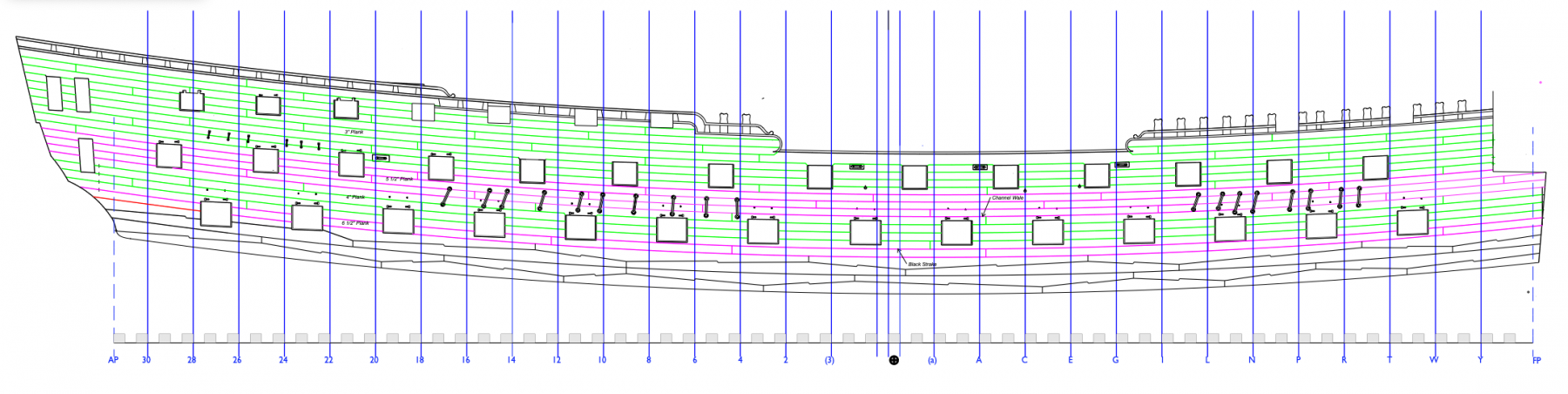
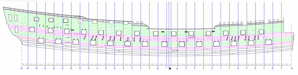
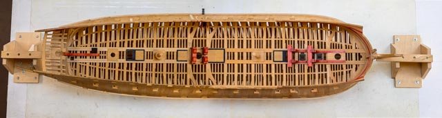
 It took me a few days to draw the planking plan. I had some difficulty seeing how planking pattern would fit onto the actual sides and interact with the various gunports, so I drew the pattern itself below the ship sides, and then projected a line up to find the appropriate place for the butts (see below). On a few butts needed to be shifted from the pattern, to avoid falling directly above or below a port. I am really appreciating my decision many years ago to do an Admiralty framing system; no planks to worry about below the main wales! I did confirm that all of the gunports have stops, whether carrying a gunport lid or not. I could see this in photos of the 2nd Bellona model, and also in Rob Napier's Legacy of a Ship Model: Examining HMS Princess Royal 1773. I don't know why they would do this, except to provide opportunities to install gunport lids later. But I cannot imagine why they would ever do this. So, another mystery from the 18th century. I have to do some experiments with how I will paint the red around the gunports. I am concerned about my red stain leeching into the ends of the planks, and am considering airbrushing the Admiralty Paints red into the edges. But how this works with my existing red stain is still to be seen... Mark
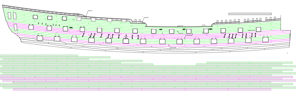
-
Phil, The sails really add to the overall character of the model. Nicely done! Mark
- 355 replies
-
- 2
-

-
- prince de neufchatel
- schooner
- (and 3 more)
-
Mike, as I contemplate planking my Bellona, I came back to your site for inspiration--you have done a beautiful job so far. I do have a couple of questions. How did you cut the ends of the planks so precisely at the ports, with an even reveal for the gunport stops? Did you draw the reveal on the frame, or use a temporary stop block in the port itself? And how did you color the joints between the planks? I am not a fan of strongly contrasting joints, and I like the subtlety of yours. I have had some success with using dark titebond glue elsewhere in my build, but would be interested in how you are doing your's. Mark
- 607 replies
-
- 4
-
-
- winchelsea
- Syren Ship Model Company
- (and 1 more)
-
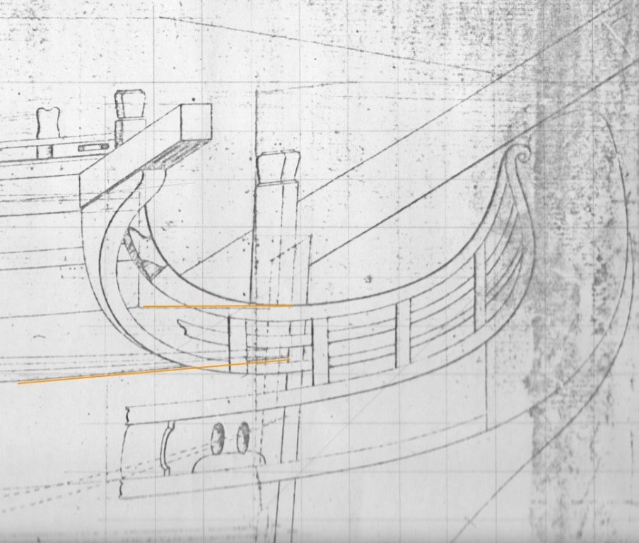
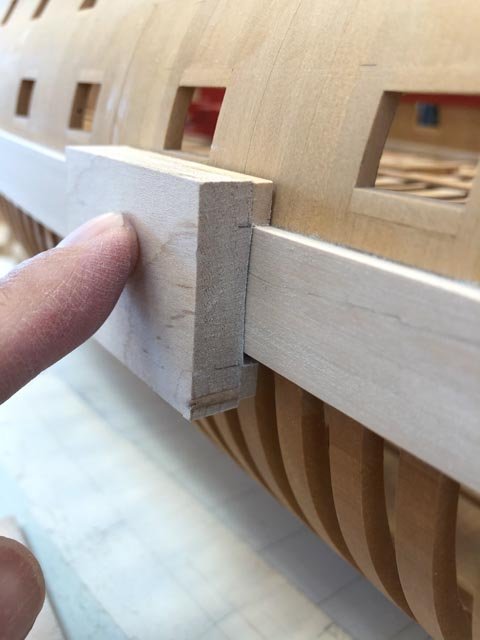
Thanks, druxey. And thanks for checking, always appreciated! In this case, the string at the bow where it hits the rabbet is at the height as shown on the draught. There is an interesting visual anomaly here. The upper edge of the bow is trimmed to match the sheer of the small platform, which is parallel to the sheer of the upper deck. And since the sheer of the outer planking is more sloped than the deck, there is a little wedge of planking between the two that does not fair with the outer planking (see below). This little anomaly will likely not show, since the headwork will later mostly cover this up. But as I look at the string again, it looks like it does need to pull up a bit between where it hits the rabbet, and where it begins to go around the bow. It does dip a little between the two data points. After sleeping on this, it occurs to me that I might as well start planking from the wales up, rather than planking the channel wale and then going back to plank in between. Starting at the wale gives me a definite edge against which to start spiling the upper planks. And as long as the channel wale is clearly lined off with the string, it should remain as accurate a placement as it would have been starting at its lower string anyway. Mark
-
Hi druxey, So as I walk around the model, trying to visualize how I start the lower strake, I see that the thread will not be a very firm edge against to start spiling planks. Would I now make a card template cut to the string line, with which I can then use to shape and test the lower edge of the actual wood plank? I would think this will be particularly needed for the first planks which will have to be steamed around the bows. Mark
-
I tried druxey's idea of string glued to the line. It is definitely easier than clamping a batten, and easier to see. the bow definitely fairs more easily. I am not quite sure how easy it will be to fit the individual strakes to this string; it was very comforting to sit the strake on the batten as I fitted its edge. Mark
-
Thanks, Gary, I see I will have to spend a little time tracking down rigging arrangements in a couple of sources to see what makes sense for the Bellona. This may be a winter project! At last, I got some time in the shop this morning. I decided to plank the sides, then mask and spray the main wales. I have too many edges on the wales against finished wood, and I am afraid that staining will leech through into the grain of adjacent wood--at least, that is what my tests have shown might happen. So I am not going to risk it. I will mask the wales, and then airbrush a number of thin layers of Admiralty Paints Dull Black. Also, planking above the wales before painting allows me to adjust the black strake to the wales' thickness with a contoured sandpaper block, and so I need to save paint for when everything is adjusted and clean. So, taking the advice of Gary and Siggi, I will install the channel wales next, coming back to plank the thinner stuff between the two. It worked for the main wales to install a batten below, and I have started with the same idea for the channel wales. However, I see that things are not quite parallel at the bows due to a big twist in the tumblehome that the batten is not accommodating well. I may have to try druxey's use of black thread point glued to the sides... Best wishes, Mark
-
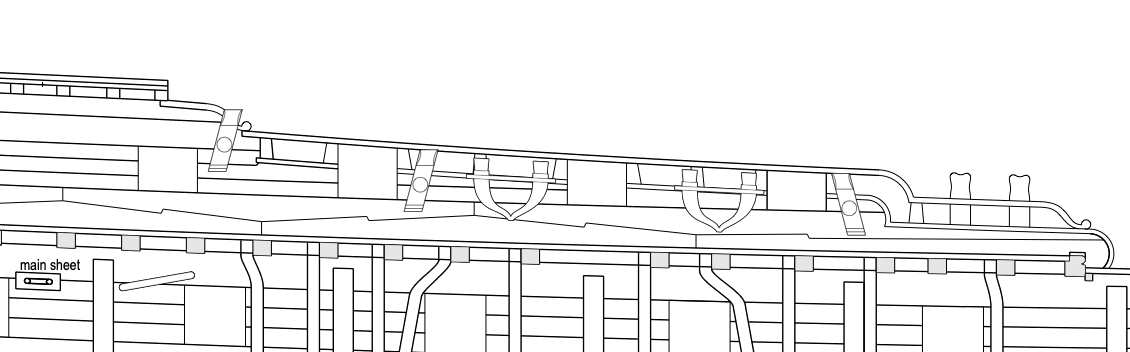
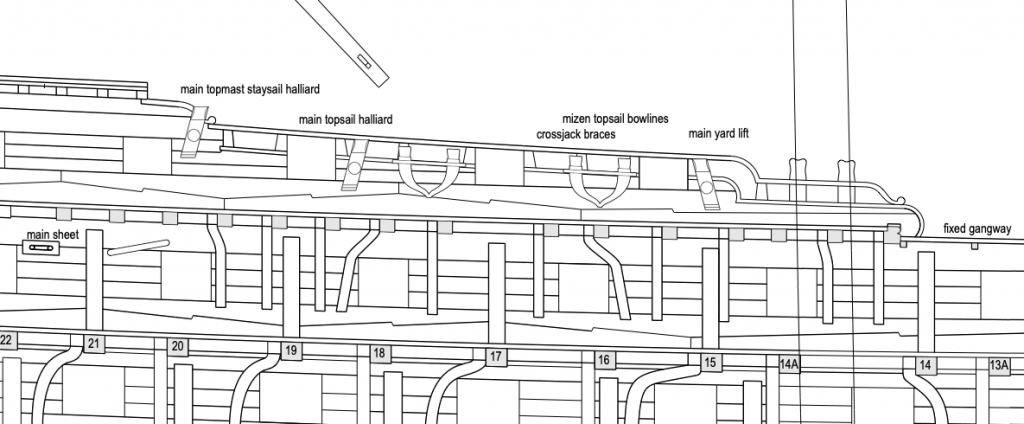
Well, this will be a work in progress. Working back and forth between Lees and Lavery, I have a first idea of the belaying points. The cavels, if I have this right, are used for the main yard, main topsail, and main topmast staysail halliards. The staghorns, or at least the foremost one, is used for the crossjack braces and mizen topsail bowlines. I cannot find a use for the aft staghorn so far. This feels very sketchy; if and when I get to rigging, I will need to find some better sources... No guests next week, hopefully some work on the channel wales will commence! Best wishes, Mark
-
druxey, aha, I had missed that plate in Lees. I'll have a good look this weekend. Thanks! Mark
-
That question is going to have to wait for another day. Lavery's rigging drawing doesn't really show any lines going to the bulwarks around the area of the mainmast. Lennarth Petersson's Rigging Period Ship Models shows a number of lines belaying to pins in this area, but the Bellona pre-dates belaying pins, and a cross reference to Lees's descriptions of belaying points (no drawing) has most of the Petersson lines belaying elsewhere. It may take a long winter evening to track down every line in the limited resources I have regarding rigging in this period. One would think that the kevels and staghorns would have belayed some pretty significant lines, as opposed to belaying to railings. Oh, well, more detective work ahead. Meanwhile, I finally got a day in the shop, and picked up again by refining the main wales in anticipation of painting them. To ensure an even thickness of the top, where the set-back black strake will reveal any inconsistencies, I made a sanding block with the right thickess for the wale as a spacer, and a curved face to match the curve of the wale. This is bringing the wales into a consistent thickness and form. A recent visitor showed off a new camera by taking three photos of my gundeck, each overlapping the other, and then stitched them together in Adobe's Lightroom to make one image, everything in focus. A nice trick I will use for later decks.... Best wishes, Mark
-
Chuck, thank you for the insights into what it takes to develop a kit. You really help explain just how complex the process really is. It is looking great! Mark
- 1,784 replies
-
- 7
-
-
- winchelsea
- Syren Ship Model Company
- (and 1 more)
-
When I was in architecture school, the first hand held calculators appeared. We asked our structures teacher if we could use them, and he said, "Those are just a passing fad. You will always have to know how to use a slide rule...." Mark
- 1,784 replies
-
- 8
-
-
- winchelsea
- Syren Ship Model Company
- (and 1 more)
-
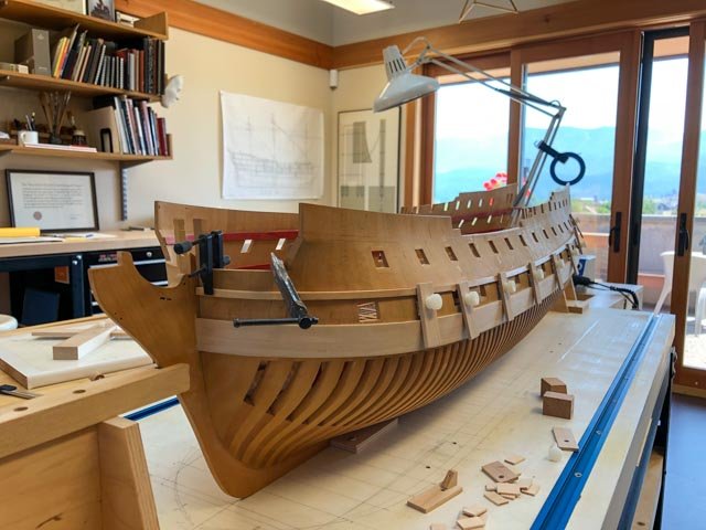
We are now well into our summer visitor season, and I have had little time for the shop. When I can sneak away, I keep working on drawing the inboard works in preparation for the planking inboard and out. I have a question for those familiar with rigging. I have copied from the image in Lavery's Bellona the kevels and staghorns on the quarterdeck bulwarks (see below). Does anyone know what lines belay to these? It will help me judge how big the sheaves need to be. There appear to be 7 belaying points per side, three kevels with sheaves and two double staghorns. Best wishes, Mark

-
Beautiful, precise planking, Mike. An inspiration. Mark
- 607 replies
-
- 4
-
-
- winchelsea
- Syren Ship Model Company
- (and 1 more)
-
Hi Greg, Fascinating, I did not know Sherline would make custom cutters. So you chuck them in the three jaw chuck on the rotary table, and turn them 120 degrees? Clever! Sorry I cannot join you in the carving workshop. Next time! Mark
-
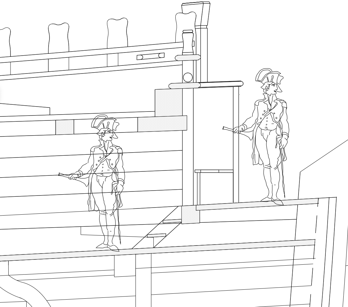
Hi Alan, good points. My interpretation of the scene is that the boatswain complained to the captain about the facilities, and the captain is making an inspection...😀
-
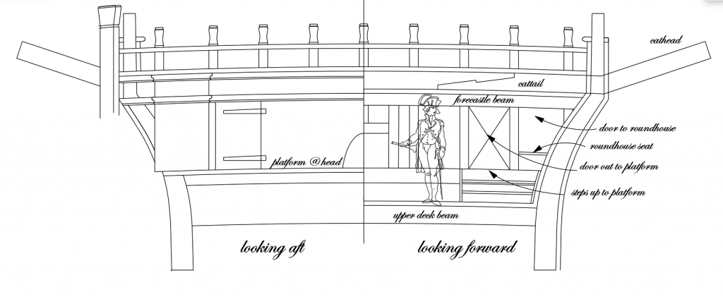
Here is the beakhead bulkhead looking aft on the left, and forward on the right. I now see the door out to the platform is just as short as the one into the roundhouse, so I guess they did not mind bending over a lot--like they had a choice... And now I see the access to the roundhouse, and knowing the seat is close to the aft end, it does not seem so awkward. Very public, next to the door out, but less public than the seats of ease on the platform itself. Thanks, druxey, I dropped the height of the seat in this drawing. It looks better than the one in the section. Now on to cutting some wood... Mark
-
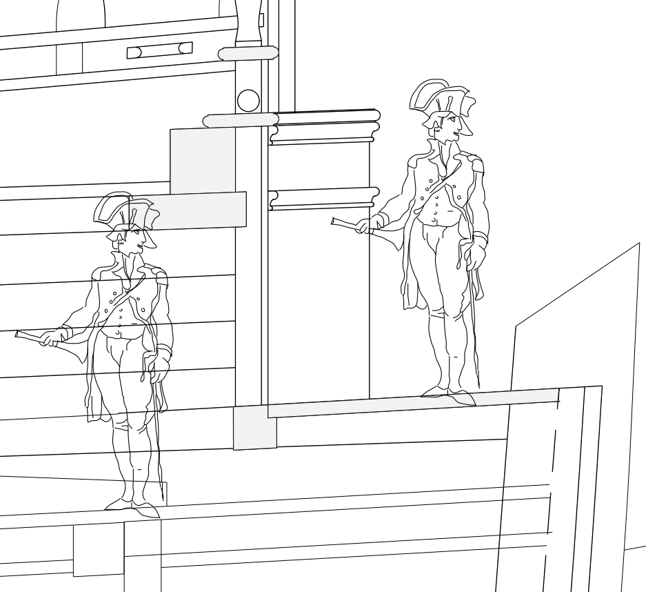
Thanks, Siggi, my mistake in not showing it clearly enough. Here is a drawing showing the platform above the upper deck, and the captain's hat is touching the forecastle deck (not shaded yet). I drew in the stool, and a possible ladder to it. This shows that the hole in the stool itself is quite close to the entrance to the roundhouse, and therefore one does not have to climb very far in. But it also shows just how low the headroom is, under the foremost beam of the forecastle (with the cattail beam above). This also shows there is no need for full headroom within the roundhouse, because one can never get in to stand up anyway. Gary, thanks, I see what you mean about the little stanchion at the outboard end. It fays into the top of the dogleg, and it is needed to form one of the verticals of the railing above. I will try to draw that presently. Mark

-
There is definitely some hocus-pocus going on with the drawings and the model. After looking at the location of the roundhouse in my paper cut-out in #1357 above, the hole barely clears the hull below while leaving little room for a door inboard; way less door than the model shows in #1360 above, and less clearance over the hull than the plan in #1358 shows. And the plan in #1358 shows a stanchion at the outboard edge of the roundhouse that could not be placed there because the dog-leg hull frame takes up the same space. druxey, I thought about whether the seat was a lower platform, but the drawing shows it well into the roundhouse, a longer distance from the aft edge of the platform beam than a typical human thigh could reach. Or, maybe the draftsman did not realize the three dimensional aspect of this feature, and the shipwrights had to move the hole within the roundhouse further aft in compensation. I am concluding it really was a tiny cubby, reached by a ladder, requiring a dextrous bending down and simultaneous twist of the body to insert oneself backwards into a space little wider than one's hips. Such were the privileges of the petty officers. At least it was better than the entirely open seats of ease out in the weather on the platform! Mark
-
Gary, Thanks, that would have to be the answer. I'll try working that into my drawings. Mark
-
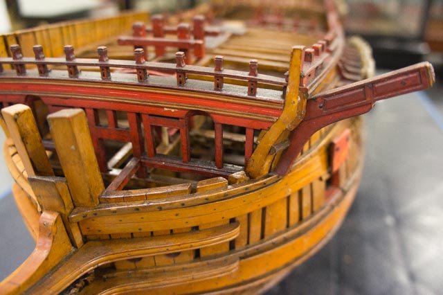
And here is my photo of the original Bellona model, showing the little door to the roundhouse opening just to the right of the arched door to the platform. That space is 3'-4" tall...
-
Gary, Here is what the original plan shows, with the roundhouse at the face of the beakhead bulkhead. I seem to recall seeing a ladder and platform in photos of another ship model, maybe the Princess Royal reconstruction. I will look around as well. This would have been impossible to use without some help aft of the roundhouse itself! Mark

-
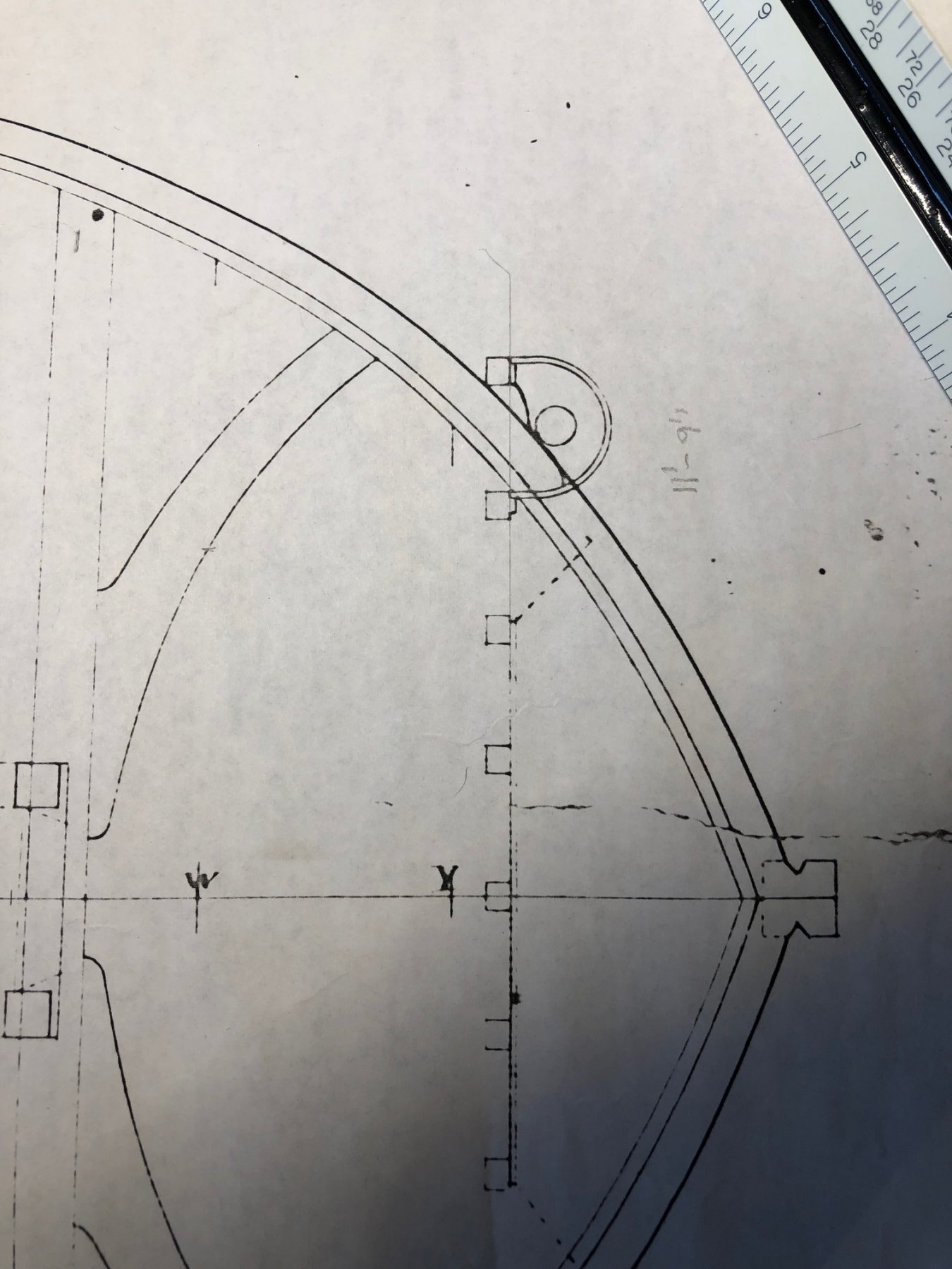
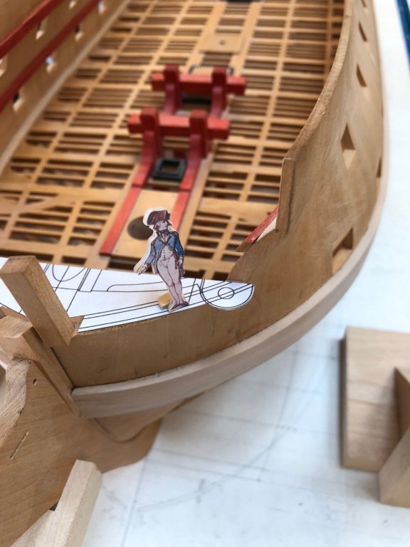
Even worse, when I see what happens in three dimensions, the hull frame (the dogleg end seen below) intrudes into the roundhouse by half its width at the floor. So the door is only 1' 4" wide at the bottom. There had to have been a small ladder up to this, with a platform for turning around and inserting oneself into the little gap opening onto the seat. Mark
-
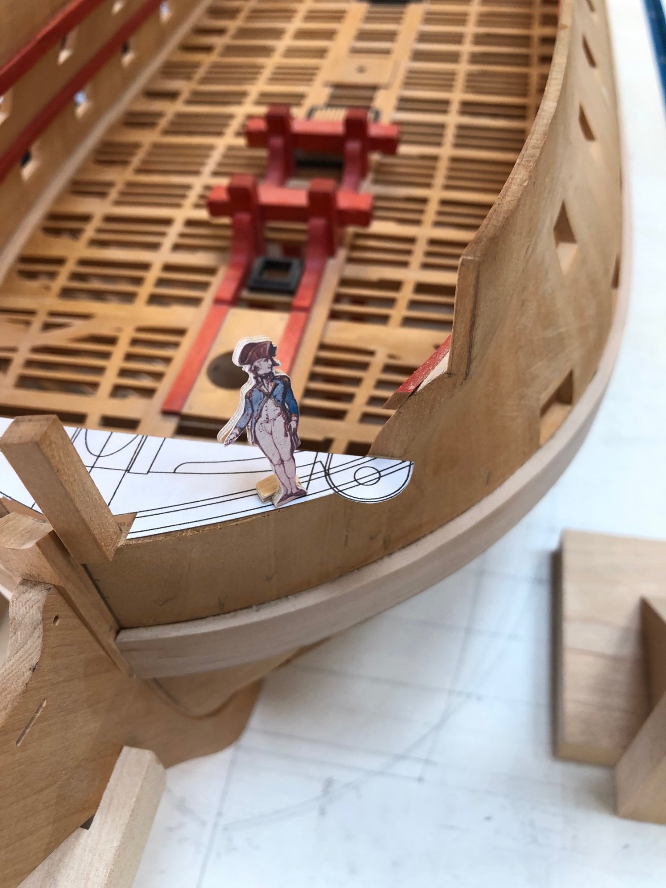
Hmm, working on the beakhead bulkhead today, I noticed that the roundhouse seat of ease for the warrant officers was a very tiny enclosure indeed, and difficult to get into. You can see the roundhouse in profile as the structure with the moldings, sitting on top of the small elevated platform over the upper deck at the bow. From my inspecting captains you can see that it is not tall enough to stand up within, and to get into it, you have to step up 2'-0" feet from the upper deck to the platform, and get through a door only 3'-4" tall. It must have been fun when you were in a hurry.... Mark

-
Hi Gary, I haven't drawn it yet, but I probably should now since I have the parts more clearly in my mind right now. Thanks for the suggestion. We have house guests coming soon, so it may be a little while before I have something to show... Best wishes, Mark