Check out our new MSW Sponsor Innocraftsman
×


SJSoane
-
Posts
1,646 -
Joined
-
Last visited
Content Type
Profiles
Forums
Gallery
Events
Everything posted by SJSoane
-
 Ed, could you elaborate on how the planing device depresses the center of bed? Or did you explain this earlier in your build? Mark
- 3,618 replies
-
- 4
-

-
- young america
- clipper
- (and 1 more)
-
After exploring how to shape with machines the hooked scarphs for the wales, I have determined that the geometry changes for each piece, and that it would be more effective to cut them by hand. I then recalled Gary (garyshipwright) installing wales for his beautiful model of HMS Alfred. (I have tried to attach a link to his site, but it appears to go to the end rather than to the relevant pages. It is somewhere around page 4). Gary temporarily attached a batten above the wale, to which he clamped the upper strakes for a fair run. Subsequent lower strakes were clamped to the upper strake. It seems like a good idea, and I will try it. I also see that Gary laid up the wales in two layers, practicing on the first layer. I will see how well I can cut and bend 8 ½" thick pieces before deciding if I will do this in two layers as well. Getting in some practice on these complex pieces makes it feel less daunting... Gary, I haven't seen a post from you for a while, hope you see this! I tried string on the port side for fairing and decided that the tape gave me something to draw against. Now that I am determined to cut each piece to fit, I will want to draw the individual parts on the model sides to know where I am going. The tape also helped me visualize whether the two sides are the same. Mark
-
Thanks, Ed and druxey. More work, but I think the circumstances here call for it. Good to know before I cut a bunch of wood too small! Mark
-
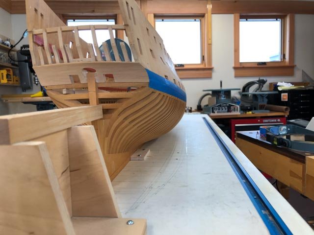
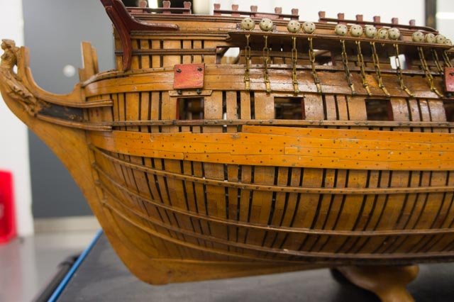
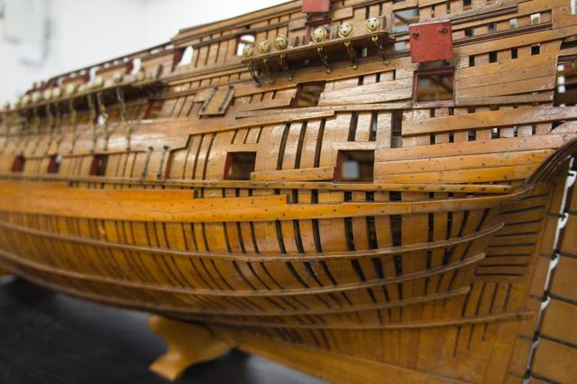
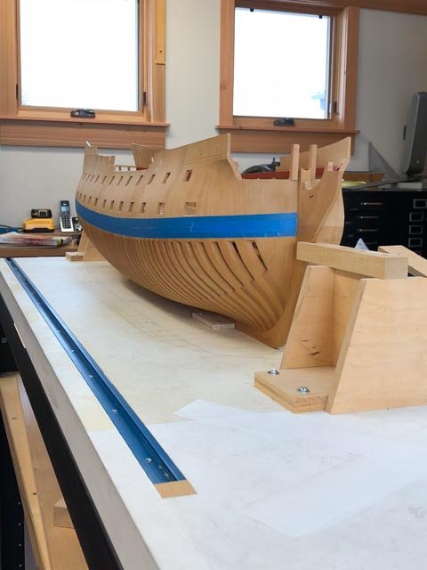
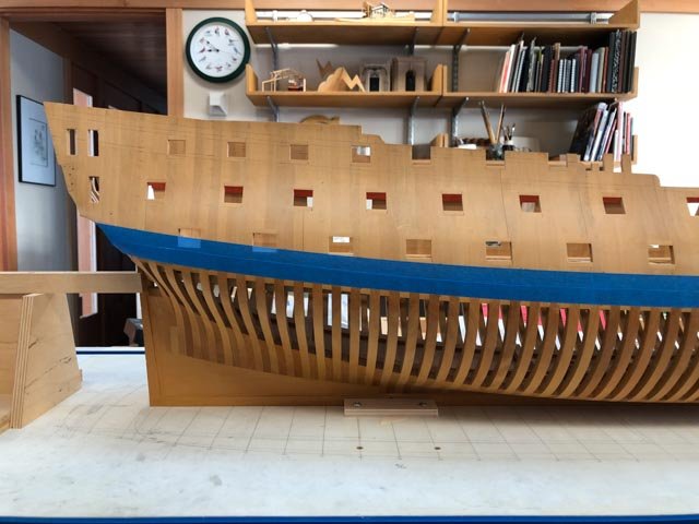
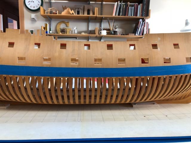
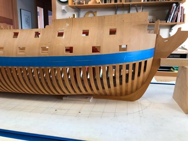
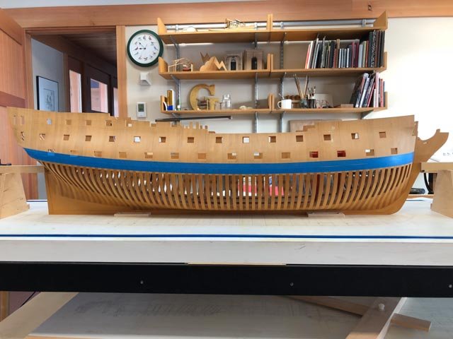
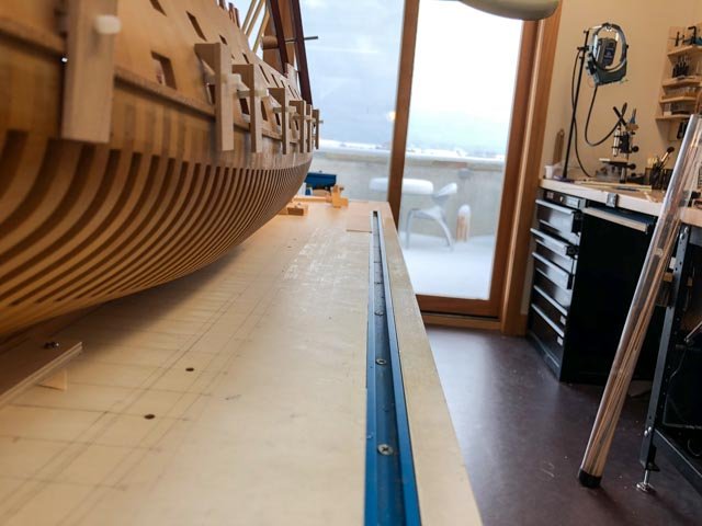
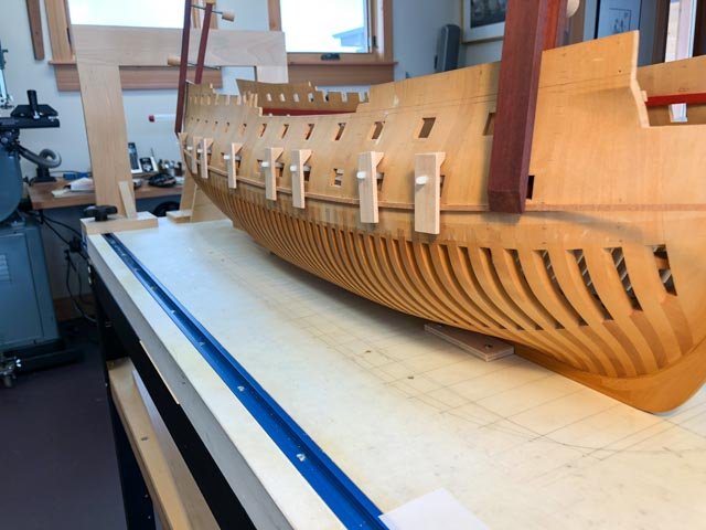
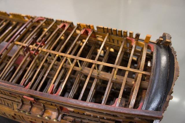
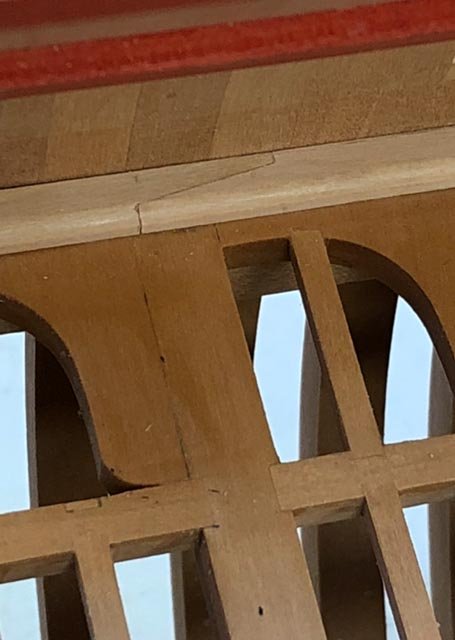
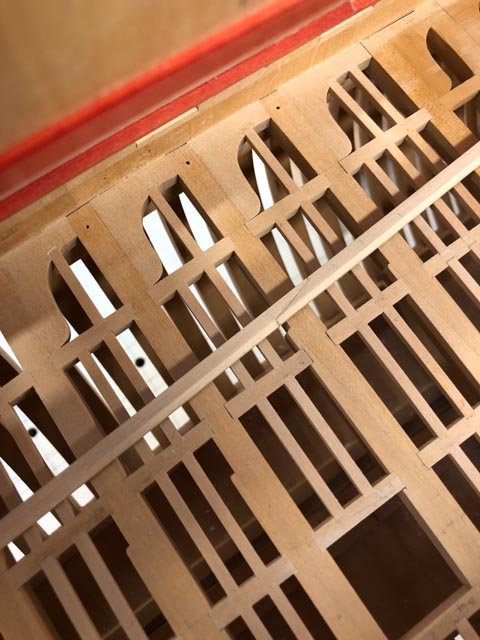
The wales have a distinctive S curve when they are expanded to their actual length and shape (1st image). That means that a number of pieces particularly at the bow have a noticeable curve to their edges (2nd image). I cut a piece of boxwood to the required thickness (8 ½" @ scale 3/16" inch = .039" actual), and this piece does not bend in its longitudinal length. So it looks to me like I need to cut blanks oversize in the transverse direction, so I can shape the required curve to the lower edge. But I have not seen any reference to this need in David Antscherl's books, or in Ed Tosti's. Am I missing something? And whether I shape these to fit, or they bend to fit, I feel I need some physical guide to align the lower edge, rather than just a pencil line. The 17th and early 18th century dockyard framing style I am building shows just a thin line of the bottoms of upper futtocks below the wales (third image). I need to keep the wales very parallel to this line or the differences will be quite noticeable. Perhaps form a temporary aligning batten that can be clamped to the frames below the wales? Or am I overthinking this? Any advice greatly appreciated! Mark

-
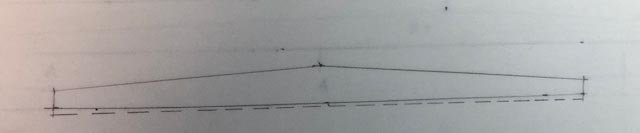
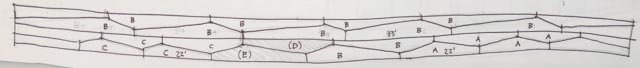
Thanks, druxey, I might try that on the port side and see which one works for me. I like the idea of tracing against the edge of the tape to put pencil on the hull, although the string might give a fairer line. Thanks, albert, I hope I can continue to make it interesting. By way of interesting, I spent the day looking carefully again at the joints on the wales of the 1760 first Bellona model, shown in frame. It is unusual, to say the least. As the sketch below shows, the top two strakes labelled with B are standard top-and-butt, each 33 feet long with 22 feet and 11 feet arms. The lower two strakes, however, are all over the place. Starting at the right side (fore), there are a number of anchor stock pieces labeled A. These are 22 feet long, with equal arms. Aft of these are 2 top-and-butts, the same as the ones in the upper two strakes, labeled B. And then there are two top-and-butts labeled (D) and (E) that are not the same size as any other pieces in the wales, nor are the arms a standard ⅓-⅔ proportion. Strangest of all, the aft end of (D) aligns with the butts of the B pieces above. This would not appear to be a good structural idea. And finally, heading aft, the wales finish with more top-and-butt pieces labeled C, which are 22 feet long, the same as the anchor stock pieces labeled A at the fore end. I have looked at the photos of the model very carefully, and I believe this accurately captures what the model builder actually created. Was it an experiment, or an accurate representation of what was really built in the actual ship? The model hull is framed differently on each side, showing some experimental ideas about framing around gunports. Perhaps this was a proposal for radically shifting butts on the wales. Wales are only shown on the port side of the model. Whatever the reason, I am determined to recreate it on my own Bellona. So now I have to think about how many of these can be cut by a standard template, as shown by Longridge's Victory or Ed Tosti's Naiad.
-
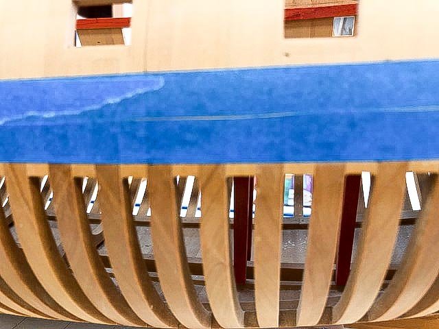
Thanks, Mike, the beauty of that underwater form keeps me going. I reflected on setting up the wales last night, and it bothered me that I could not see the fairness of the wale past the clamps on the batten. I re-read appropriate portions Ed Tosti's Naiad book, and saw that he used painter's tape. I tried this, and it works much, much better. I can see both top and bottom. And sighting down the length really highlights the low or high spots. In this case, I saw a low spot at the fifth gunport from the bow, and could fair in another piece of tape to get the edge just right. Thanks, Ed, much better process. Now, thinking about how to cut the hooked scarph joints that are so distinctive in the first Bellona model of 1760. Mark
-
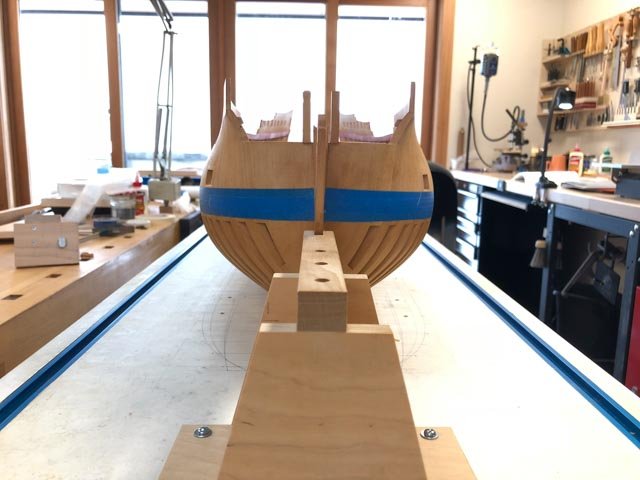
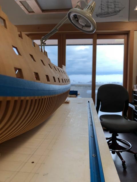
Time has begun to work on the wales. I have clamped a batten to prove the upper edge, and will live with it a night to see if it still looks fair in the morning. You can see the snow piling up out the window; good time to work on the ship! Mark
-
Hi Rusty, I am just catching up on your build. What brand of red ochre did you use for the red? And I didn't see how you colored the wales and other black stuff. Best wishes, Mark
- 310 replies
-
- 2
-
-
- cheerful
- Syren Ship Model Company
- (and 1 more)
-
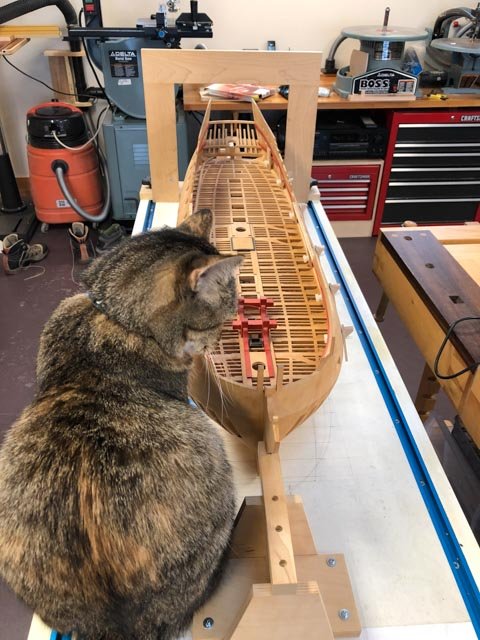
If I remember the story correctly, it would require a pea green boat, and I am too far along to consider a color change...tough luck for the cat! I did manage to glue in the waterway on the port side, masking the deck so the glue would not go astray. The ship cat did not help, since she was busy drinking out of the jar of water I was about to use to clean my glue brush. Can't get good help these days. Mark
-
Thanks, everyone, for this help with the wing transom knees. I have completed the gundeck waterways, ready for installation. I have pondered whether I can get these glued and clamped within the 5 minute "open time" for Titebond Original glue. I consulted with the ship cat, and she agrees that it would be risky. So a trip to the store to find some Titebond III, with an "open time" of 10 minutes. Good thing to have a smart ship cat. Mark
-
Hi Mark This is very interesting. Looking up the list of ships similar to the Bellona, I see that Saturn, Elephant and Bellerophon are all of the Arrogant Class, which Brian Lavery notes has the same design dimensions as the Bellona class. The Elizabeth class, which includes the Berwick and Bombay Castle, is just a foot longer in design dimensions, and so likely close enough for the scale I am working at. So even though these are almost a quarter century more recent than the Bellona, they are likely to have the same scantlings. And there is nothing to be found closer to the Bellona's 1758 design date anyway. Are any of these available online, or for purchase from the NMM? I did not have any success finding any of these on the NMM website (although I did find the Lieutenant's logs for the Bellona from 1760). Best wishes, Mark
-
On reflection, maybe the hooked scarph joint looks more like this. This would bring more wood fibers into resisting the tension along the joint.
-
Hi Ed, Thank you, this is very helpful. I think you identified the reason for the curved or straight knee, and it appears to do with assuring that the knee and the spirketting are locked together. In the case of the Bellona, the top surface of the wing transom is aligned exactly with the top surface of the upper strake of the spirketting, and so these would lock in the same horiontal plane. In the case of the frigate, the spirketting is below the wing transom, and so would need the curved knee to connect together. This makes structural sense. Just out of curiosity, which way would the hooked scarph be arranged? If I understand the structural role of the wales and spirketting, it is to help resist the hull's tendency towards "hogging", where the bow and stern tend to drop down due to greater buoyancy midships. So the wales and spirketting are put into tension, not compression along their lengths. This means that the hook in the scarph would be aligned as shown below. Would this make sense? (I am not sure I am going to cut the hook, but I am interested nonetheless). I have seen no reference to a contract for the Bellona, including in Lavery's books which focus on the ship. I had assumed all these years I have been working on this that no contract exists. But I should look into this. Is anyone aware of a contract for the Bellona? I will try contacting the NMM. Best wishes, Mark

-
Ed, I have such a lot to catch up on with this build. You continue to educate us all, with your endlessly refining techniques, and thoughtful historical reconstruction. Mark
- 3,618 replies
-
- 5
-
-
- young america
- clipper
- (and 1 more)
-
Gaetan, Those photos feel like the ship is looming out of the mist. Beautiful! Mark
-
I knew this would get interesting! The only primary sources I have for this are: The image of the half model of HMS Ajax 1767, showing a straight fore and aft arm, without an S-curve. But as best I can see, this model does not have spirketting and the arm appears to fay onto the frames themselves. (I see this in Lavery's Bellona, p. 27.) The image of the repair Rob Napier did in this area on the contemporary model Princess Royal 1773. Again, a straight arm without an S-curve, and in this one the knee abuts the spirketting. See p. 58. And then there is Mark P.'s contract for the Bombay Castle, noting a hook scarph to the spirketting. this is 1782, almost a quarter century after the Bellona. I tried staring down into the image I took of the Bellona at Chatham (see below) but too far in the murky depths to see... Secondary sources are: Goodwin's drawing of the knee on page 30, abutting the frames, no S-curve. (the members in this drawing have always seemed out of scale to me, by the way). John Franklin's model of the Egmont 1768 in Goodwin, page 45 showing the wing transom knee as straight and abutting the frames. As far as I can see, he did not include spirketting, or I cannot see a later image of this area that would show. The one common feature is a straight knee, with no S-curve, while the primary sources disagree in showing one on the frames and another on the spirketting. But both primary sources are stylized models to a certain extent, and therefore not entirely reliable as guides one way or the other. I am inclined to think that Ed and druxey, who think like shipwrights solving problems, have the right idea. The spirketting continues aft to the transoms, and is scored for the wing transom knee. otherwise, the upper strake of spirketting would basically stop at the fore end of the knee, weakening its longitudinal strength at this critical aft location. I think the knee fore and aft arm is probably straight, not S-curved, for this 74. So, the wing transom knees have to increase their transverse dimensions to include the distance they would be set into the scores in the spirketting, leaving them still 6" proud of the spirketting at the fore end, if Goodwin has this dimension right. Ed, your score looks about halfway into the spirketting; I will follow suit! Mark

-
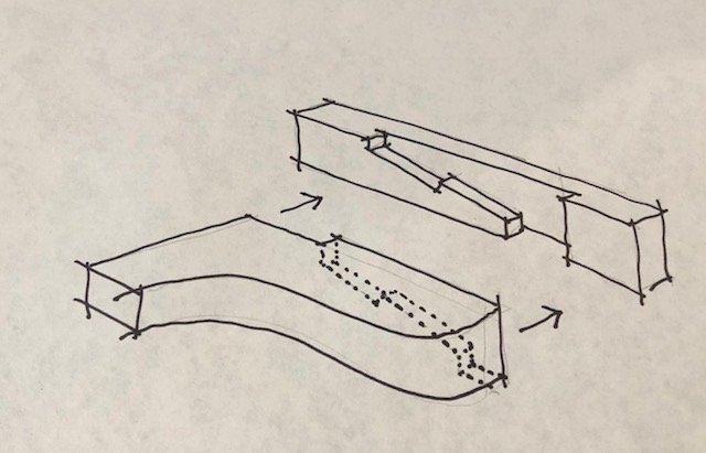
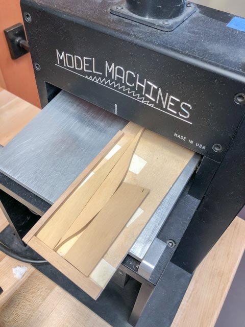
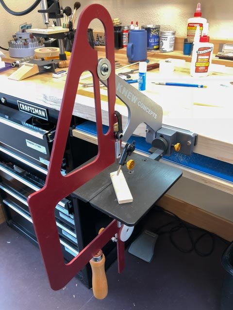
Using small off-cuts. Since this shipwright is now living in retirement, wood has to be used as frugally as possible. I have boxes of off-cuts from earlier work, because I previously tended to cut pieces out of freshly cut large sheets. I did this to keep fingers away from blades, and also to be long enough to go through the thickness sander. So as I ponder many small parts still coming, like knees, I considered how I could manage using more of my off-cuts. To solve the thickness sander issue, I built a simple sled. I was able to attach a number of off-cuts to it with double sided tape. The tape adds .005" to the height of the top side of the wood to the top of the sled, so I use the depth indicator on my calipers to check the thickness after each pass, subtracting .005" from what I measure. Because my power scroll saw sometimes grabs at small pieces, particularly when they are only caught by one side of the foot, it makes me nervous on little parts. So I have tried using the Knew Concepts hand scroll saw shown below. It is a little slower, but much less nerve-wracking. Wing transom knee. I came across an interesting issue regarding the wing transom knees. Goodwin's book says the knee attaches to the frames, and the thickness of the knee at the fore end of the fore and aft arm is 6". But the spirketting is 7" thick at the waterway and 5 ½" at the top just under the ports. So the wing transom knee would be buried in the spirketting, which does not seem right. Rob Napier's book on the contemporary model Princess Royal shows the wing transom knee fayed against the spirketting. Was this a modeling convenience, and if not, would the wing transom knees have a thicker dimension on the fore and aft arm in order to accommodate the spirketting? and I thought this was going to be an easy piece! Mark
-
Druxey, I will have to try the party trick. I will give you full credit at parties if I can do it! Mark, thanks for the information. I will try that against my hull dimensions, and also to the Ajax model closer to my time period, to see if anything significant changed from 1760 to the 1770s and 80s. Mark
-
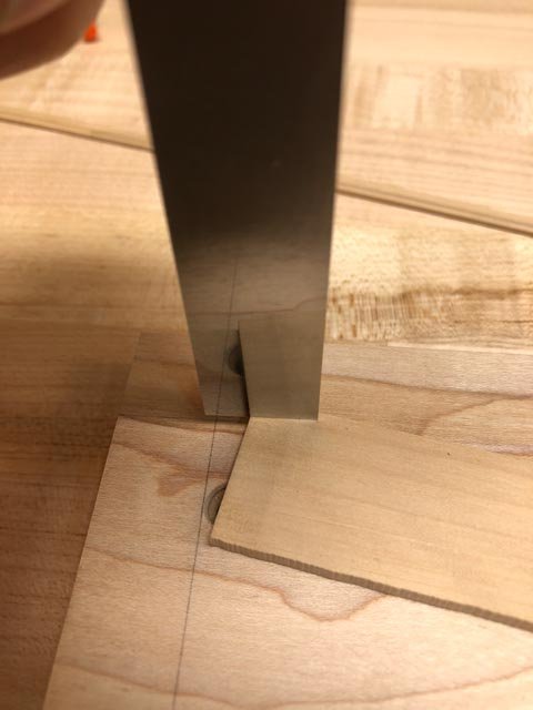
I am starting to get back into the swing of things, working on the gundeck waterways. Starting my new retirement phase of construction, I resolved to begin cutting as many joints by hand as possible. I had earlier relied on building extensive jigs for machines to control quality, but I have been inspired by the books by David Antscherl and Ed Tosti regarding how to do this with chisels and files. I also took to heart Gaetan's good advice to me a few years ago that the more one repeats a task, the better one gets at it. I learned this when cutting the mortises for the carlings and ledges in the gundeck itself. So here is the port waterway ready to be installed, with handcut scarph joints. The last photo shows a little trick I tried successfully to keep the chisel perfectly vertical to the cut. I drew a line on the cutting block, which is reflected in the back of the chisel. When the line is straight between the block and the reflection, the chisel is vertical. Best wishes, Mark

-
Dave, thank you for your kind comment. I am discovering that I have forgotten a lot about the project having been out of the shop for well over a year, and am not quite in the groove for getting going again smoothly. But I am working on it each day. Hopefully, it will start to flow again. Hand cutting scarph joints on the waterways is helping focus my attention! Mark, if you have dimensions for a 74 circa 1760 wing transom, that would be great. The Bellona, I have read, was first called a 70 relative to the 1745 Establishment, but its dimensions are closer to an 80. I believe this is because the shipwright Slade was sneaking a new idea of a 74 through the Admiralty and had to relate it back to the Establishment figures. So it does not always compare well in dimensions to later 74s, in the Repository or Steel dimensions. Part of the fun of building the Bellona! Best wishes, Mark
-
Just found the answer to my question, looking at the model of the lower deck of the Ajax of 1767, illustrated in the Lavery book on the Bellona, p. 27. Also, Goodwin mentions it on page 26.
-
Thanks, Greg, it is great to be back in the shop! While working on the gundeck waterways, I starting thinking again about the arrangements at the stern. I had long believed that there is a wing transom knee as shown in the red lines below. I saw this in Peter Goodwin's Construction and Fitting of the English Man of War, p. 30. But I find no other information about it in Goodwin, and I cannot find images of it elsewhere, or dimensions ca. 1760. Goodwin only explains in more detail a knee on the helm port transom just above the wing transom, but does not show this additional knee in the drawing on page. 30. Can anyone point me in the right direction on this elusive wing transom knee? Absent from the shop for well over a year, I am having a little trouble remembering the various resources I have referred to in the past; apologies if this is in a really obvious reference... Best wishes, Mark

-
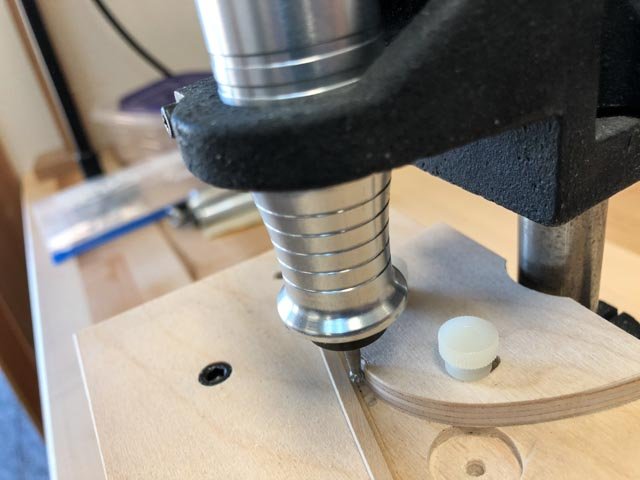
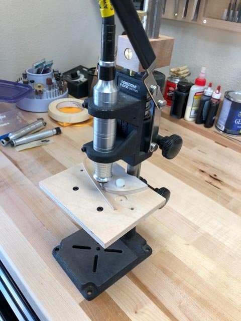
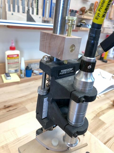
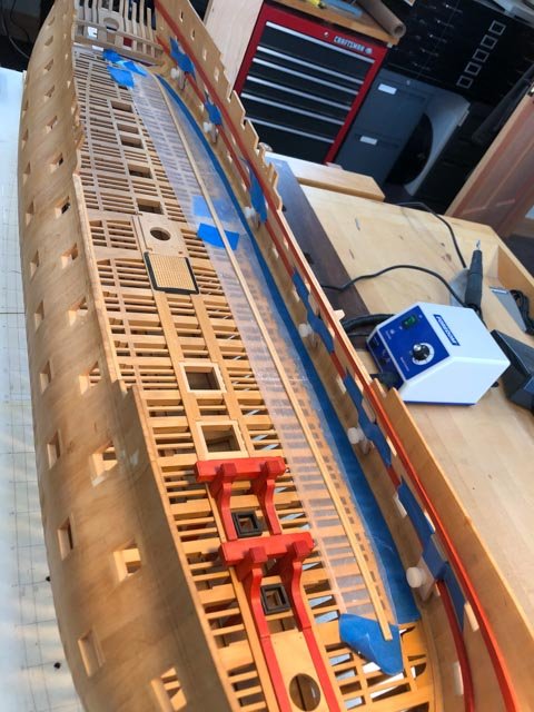
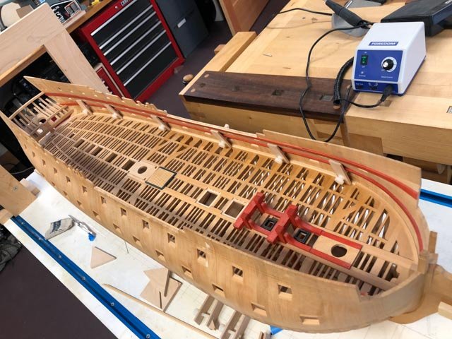
Now the shop is set up, it has taken some time to remember where I left off, and what I need to do next. I have focused on the waterways on the gundeck. The Bellona waterways have a quarter circle rabbet in the edge. I reviewed Ed Tosti's Naiad book on this process, as well as David Antscherl's Fully Framed Model, for ideas on how to cut a rabbet on a curved piece. I settled on the Foredom in its drill press. To be able to moved the burr up and down and back and forth precisely, I added a few fixtures to the drill press. The top fixture clamps on the upright, and the brass screw allows precise up and down adjustments pushing against the saddle holding the Foredom. The white screws allow the fence to move back and forth precisely. Best wishes Mark