schooner
-
Posts
743 -
Joined
-
Last visited
Content Type
Profiles
Forums
Gallery
Events
Everything posted by schooner
-
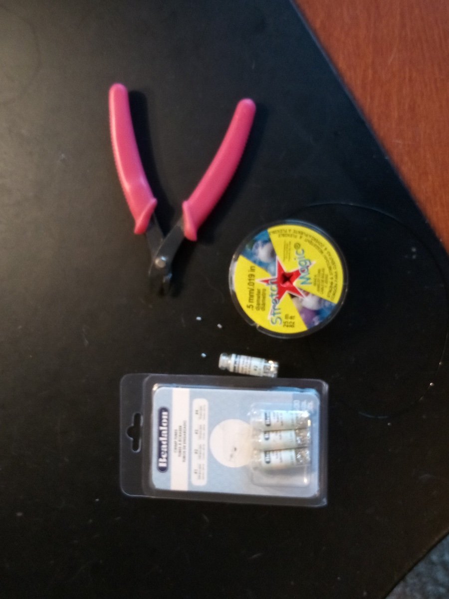
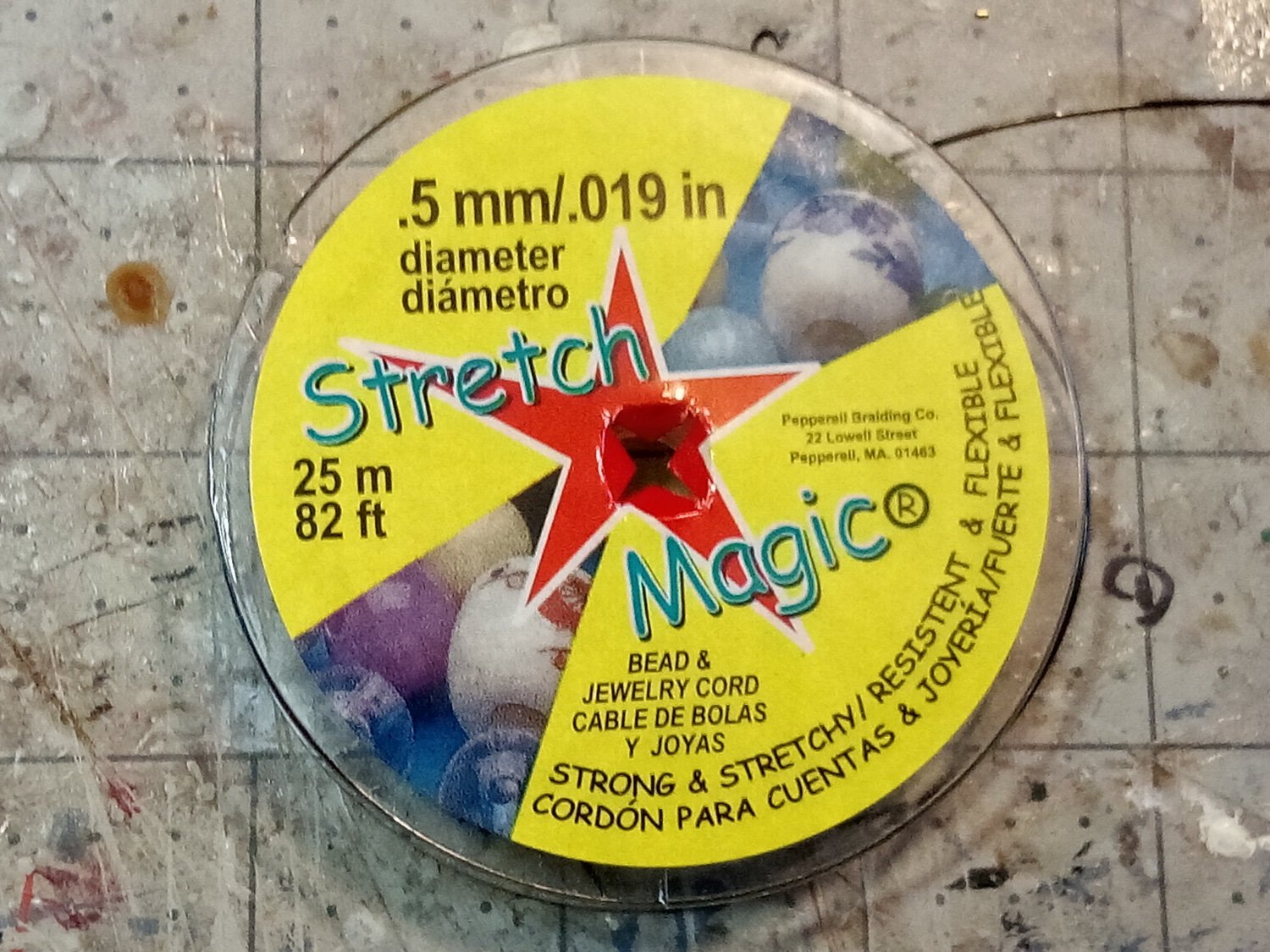
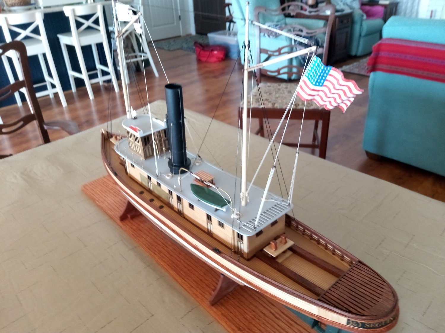
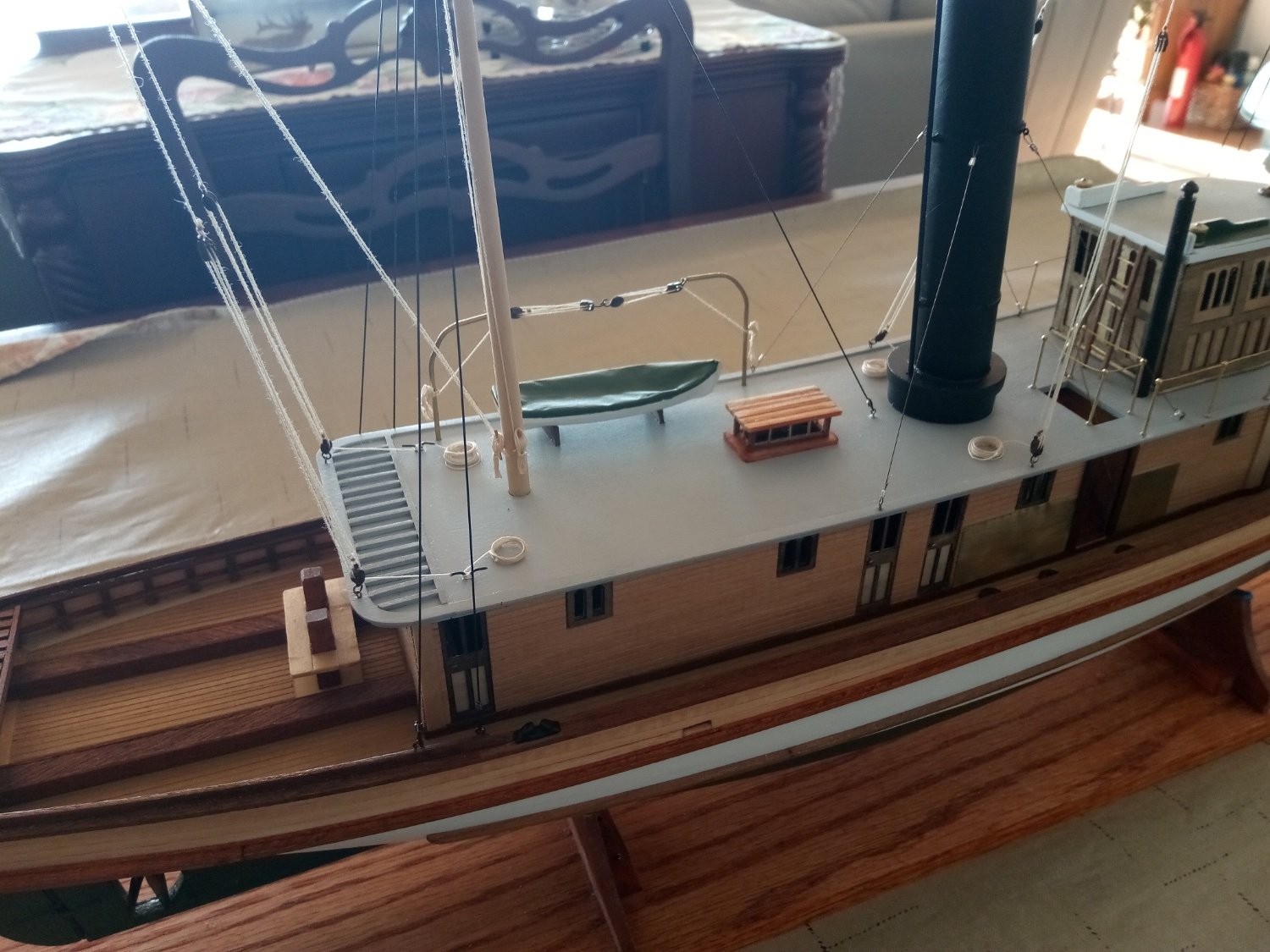
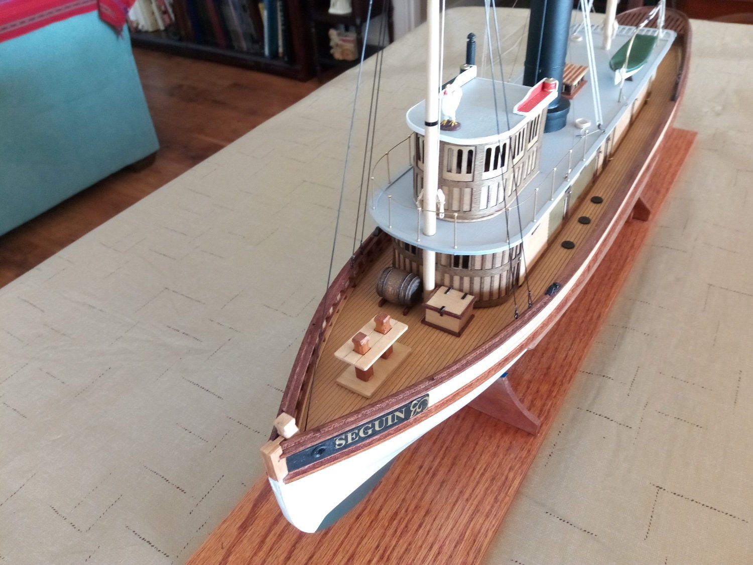
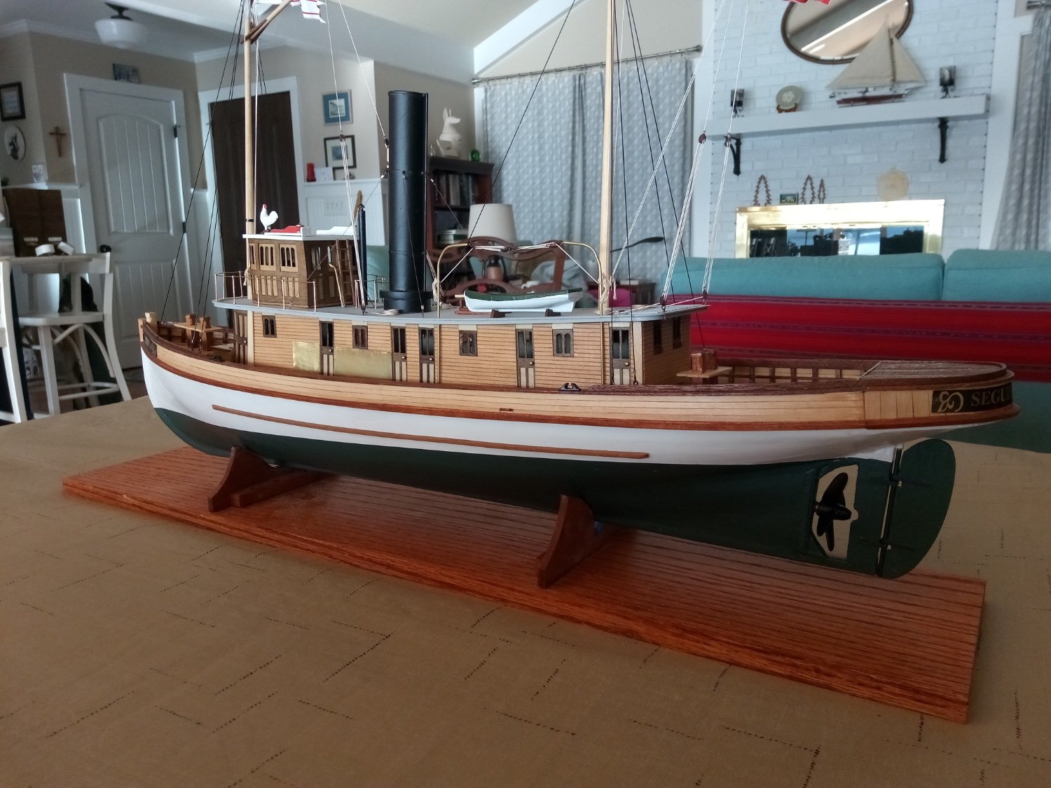
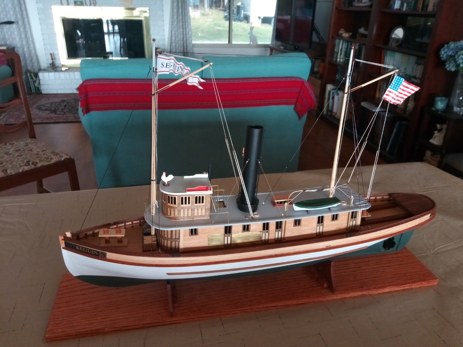
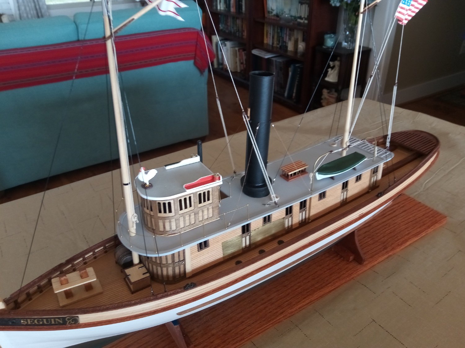
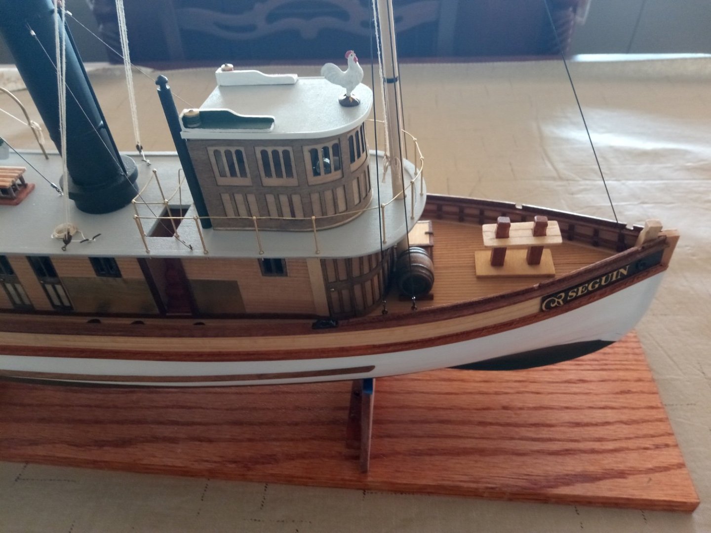
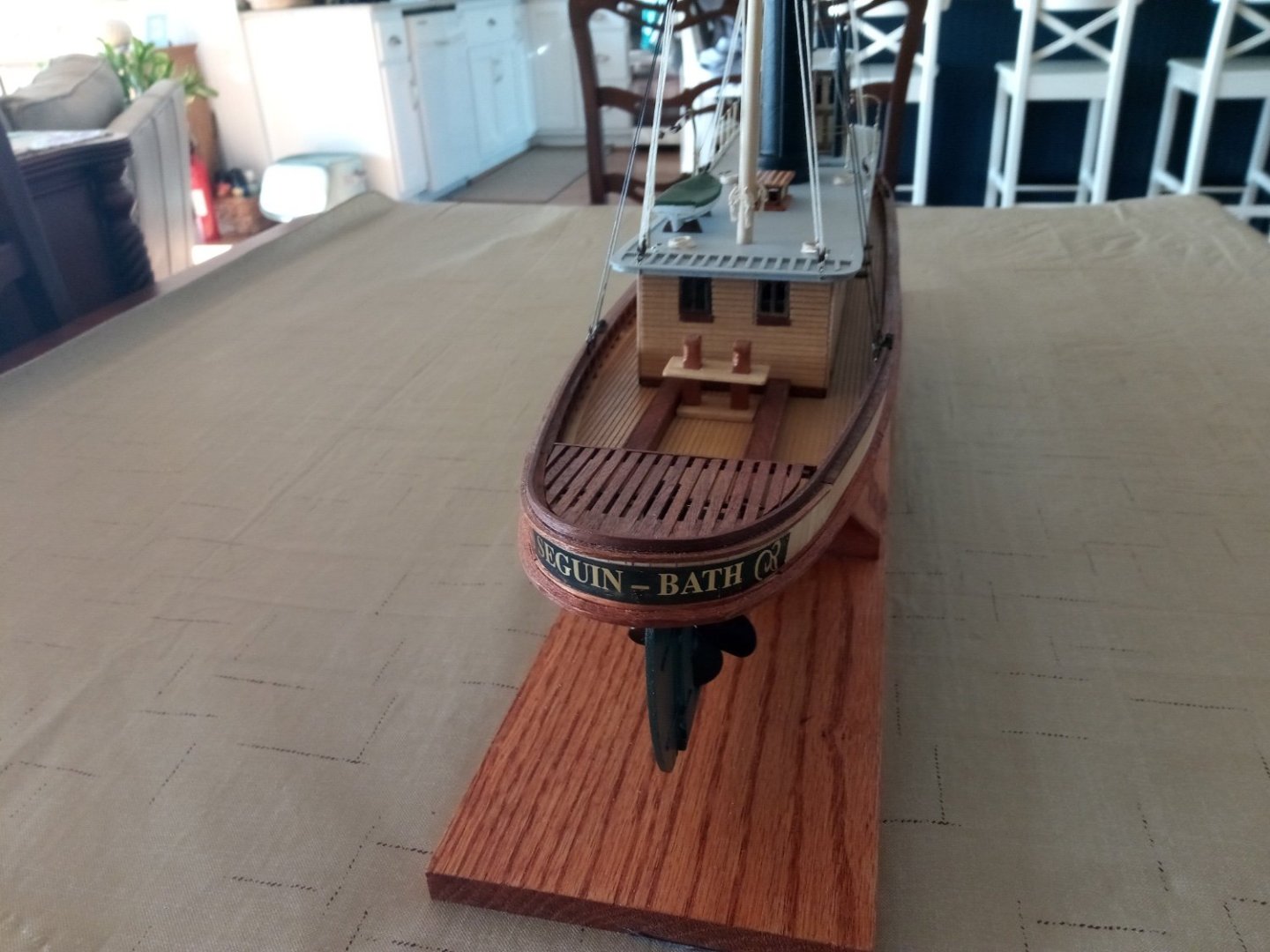
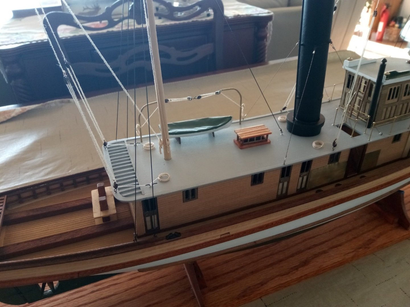
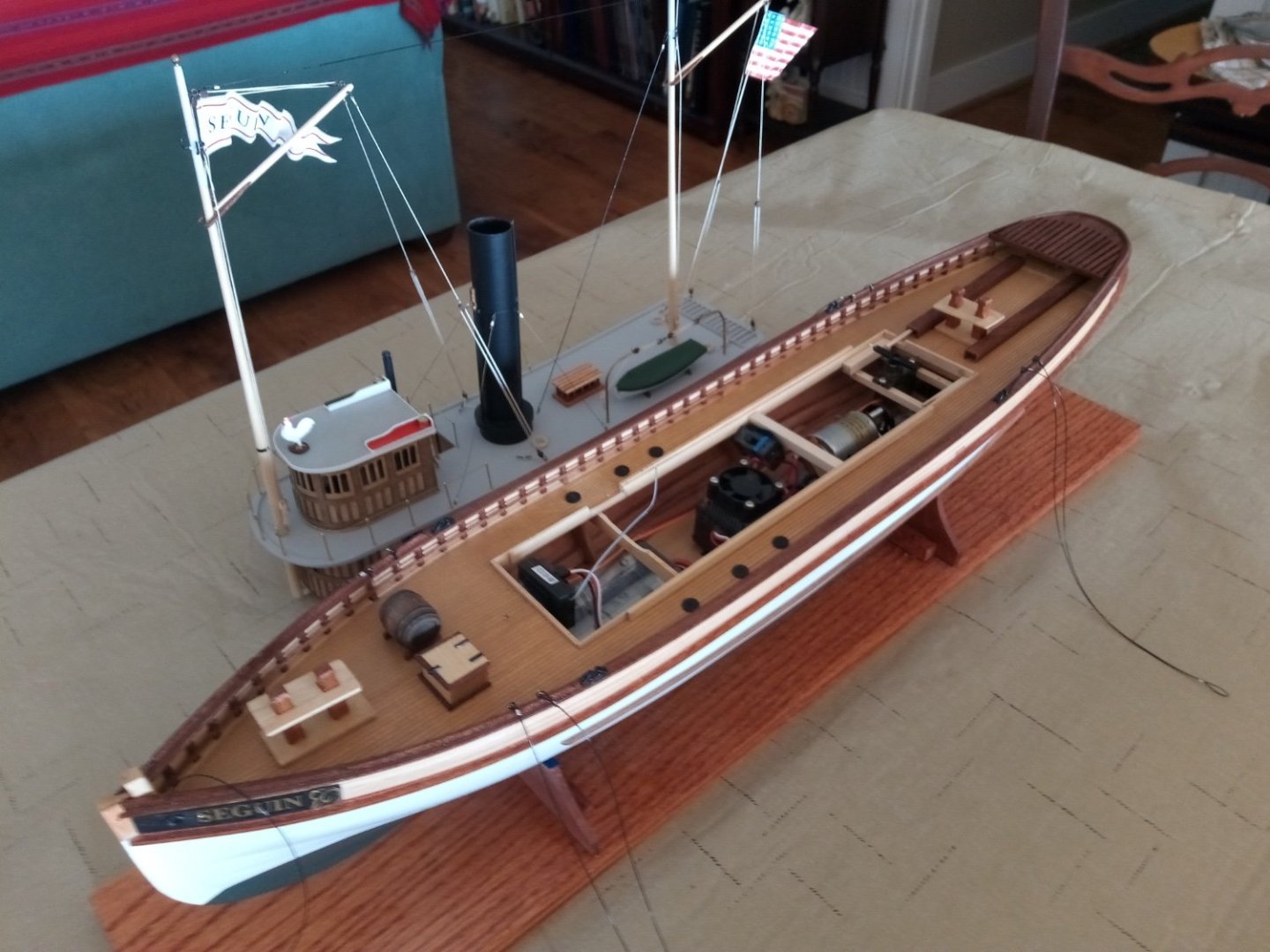
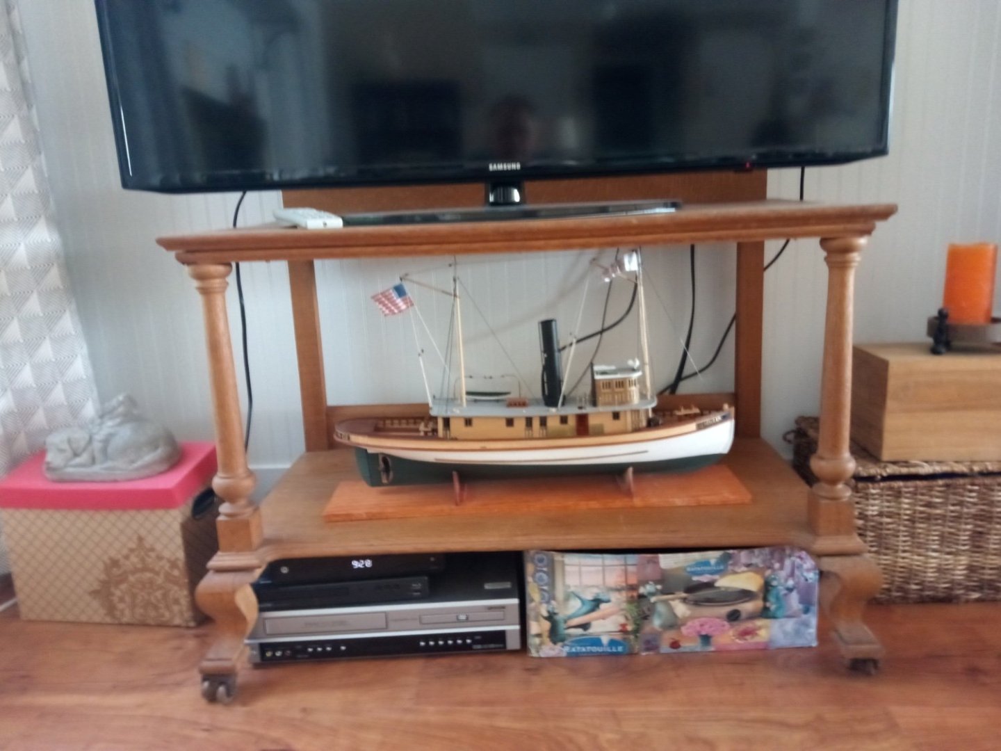
 21. Ship’s Boat and Final Rigging The Boat The instructions call for carving a provided block of wood into a boat shape -that's beyond my skills so I ordered a 3 3/16" britannia boat from blue jacket and covered the top with tracing paper to simulate a canvas covering. Standing Rigging For the shrouds and stays I followed the recommendation in the instruction book for the RC option and used black stretch cord (.5mm) that I bought online. To secure them I used .015 inch crimping tubes. Previous build logs, as confirmed by the plans, reported that the after boat davit is completely blocked by the shrouds on the port side of the aft mast so I moved both davits 1/2” forward. Several build logs reported a problem with the shrouds impinging on the deck house roof. I found that if I anchored them on the inboard side of the cap rail that there was no problem. The stretch cords, set to be about 1 inch short of their pre-stretched final length, hold the deckhouse firmly in place but are easy to lift off of the hooks on the mast so the house can be removed. Running Rigging and the flags The model comes with a gaff boom on each mast. I assumed they were there as part of an emergency “get home” sailing rig. If so, the rigging on the plans did not make much sense to me so I copied the gaff rigging used on my model of the USS Olympia (built at the same time as the Seguin) and added double blocks to the gaff vangs and changed the rigging of the gaffs themselves. The paper flags are from the kit. I rubber-cemented a piece of aluminum foil onto the back of one half of the flag, leaving a border around it for paper to paper gluing. When dry I placed the halyard in the fold crease and then folded and glued the flag halves together. Two different size dowels were used to impart alternating curved folds. Although the dowels could just as well be used to make the flags hang limply I wanted the Seguin to look as if she is headed down the Kennebec River under a full head of steam to pick up a schooner to tow into Bath for an extortionate fee. The only thing left to do now is to design and fabricate a launch/recovery/carrying cradle, probably from PVC piping and then conduct the maiden voyage, but that will have to wait until Nov when we get back from a road trip out to the West Coast.


- 72 replies
-
- 15
-

-

-
- Seguin
- BlueJacket Shipcrafters
- (and 2 more)
-
That is one sharp-looking model! Your "chrome" stanchions" look great, I'll have to remember that trick.
-
Paul, Thanks for clearing up a mystery for me. Searching for the tug's namesake I googled and googled "Seguin" but all I could find was a hero of the war of Texas Independence who died shortly before the Seguin was built. Even though during the Mexican War he fought against the US, Texas didn't hold a grudge against him and named Seguin Texas after him. I thought it was strange and unlikely that Seguin’s owners would go so far afield for a name but now I know there is a Maine connection. So much for leaving this model to the Seguin, TX public library in my will.
- 72 replies
-
- 2
-

-
- Seguin
- BlueJacket Shipcrafters
- (and 2 more)
-
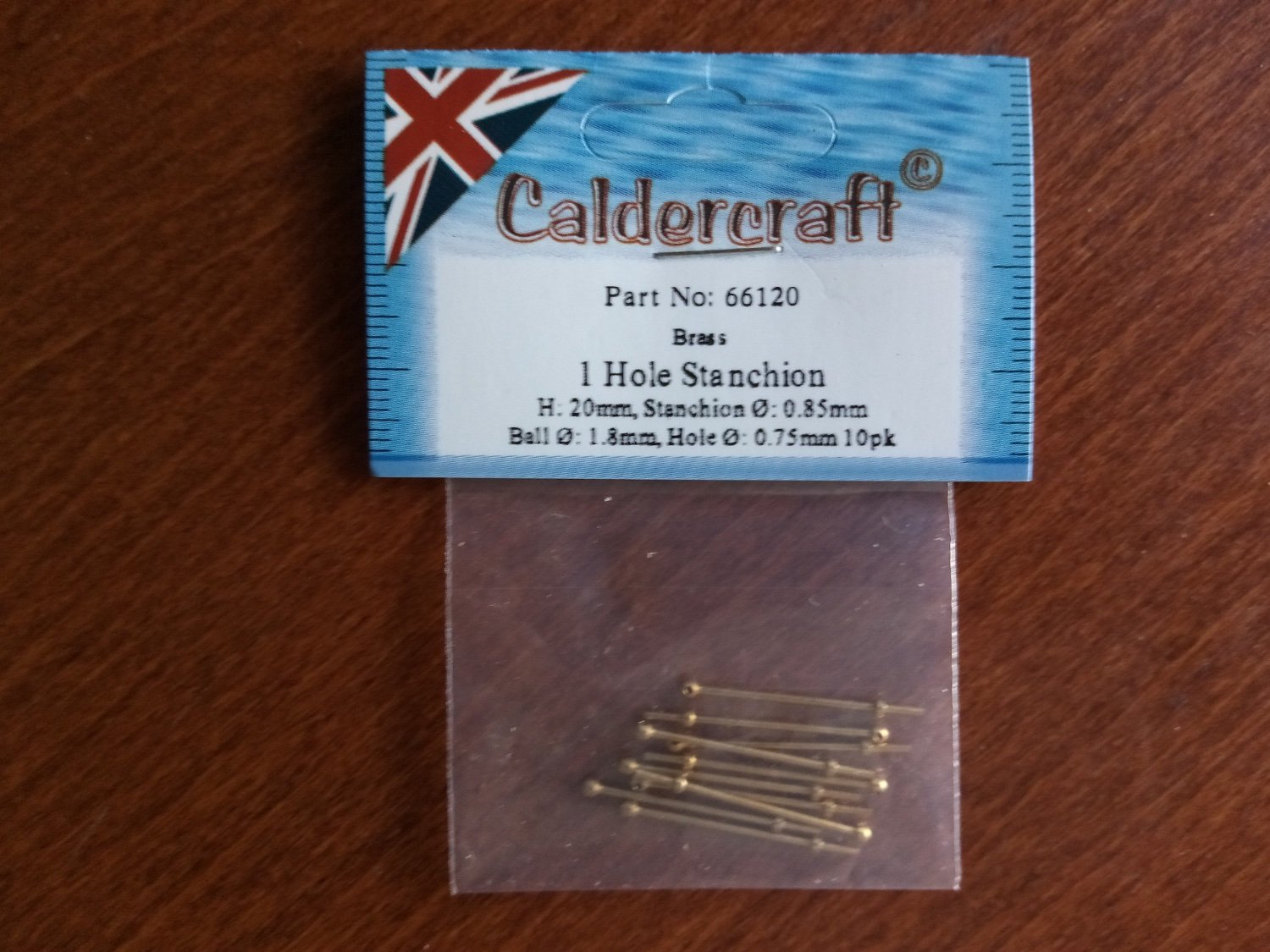
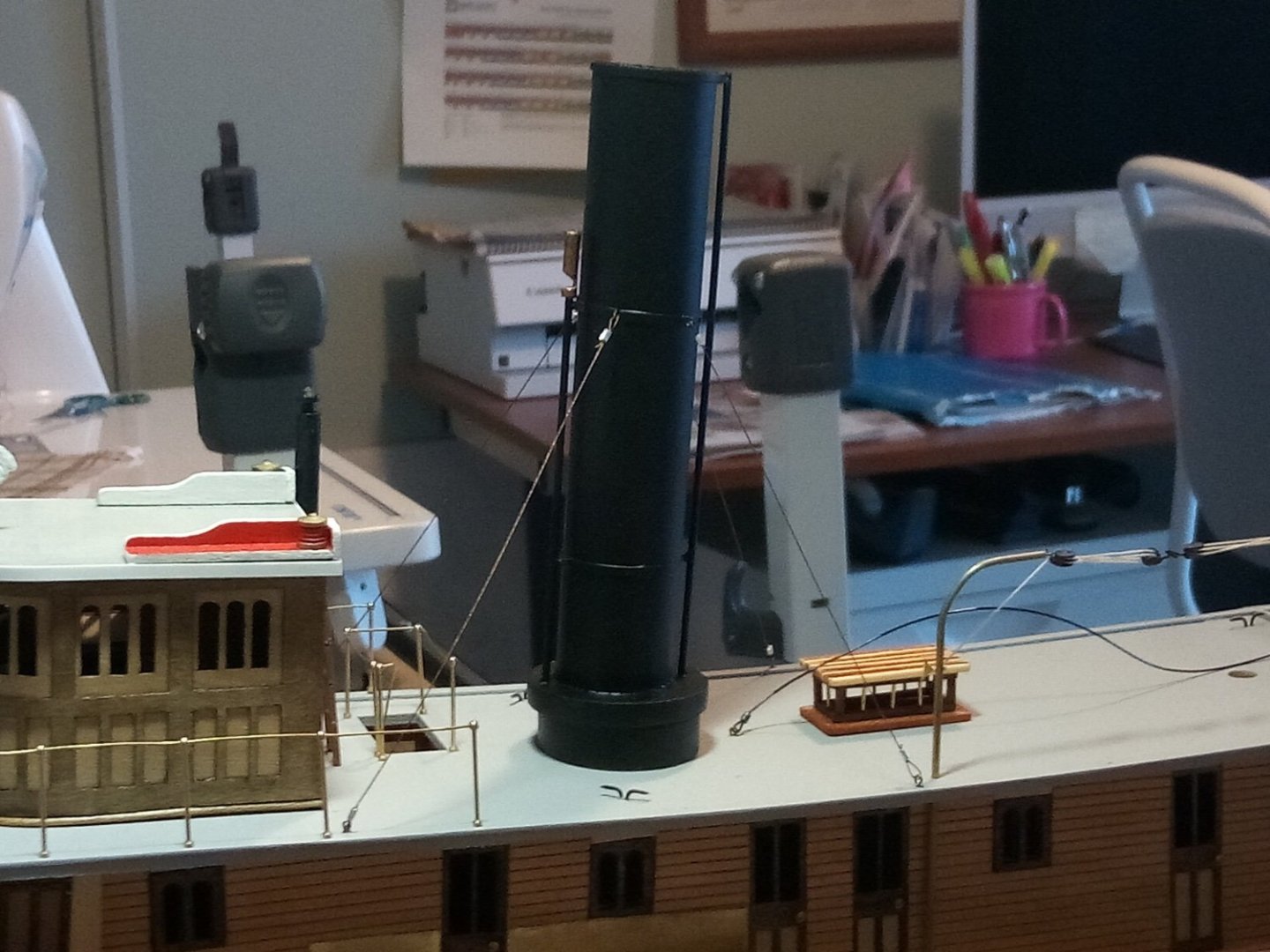
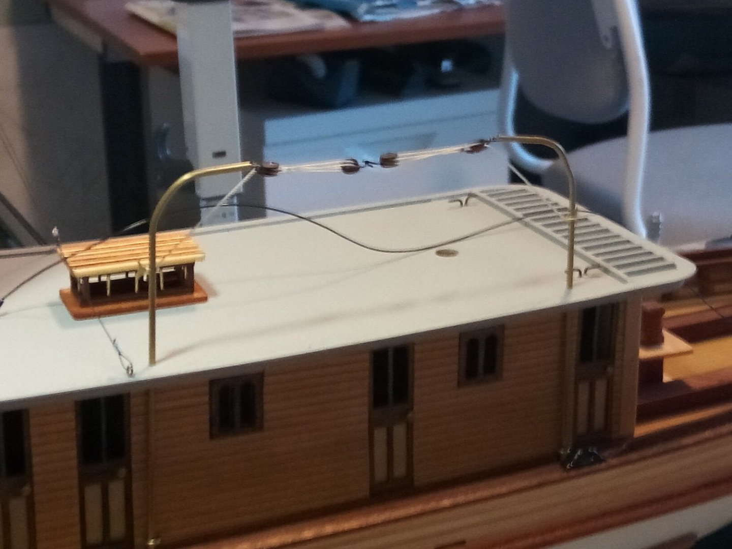
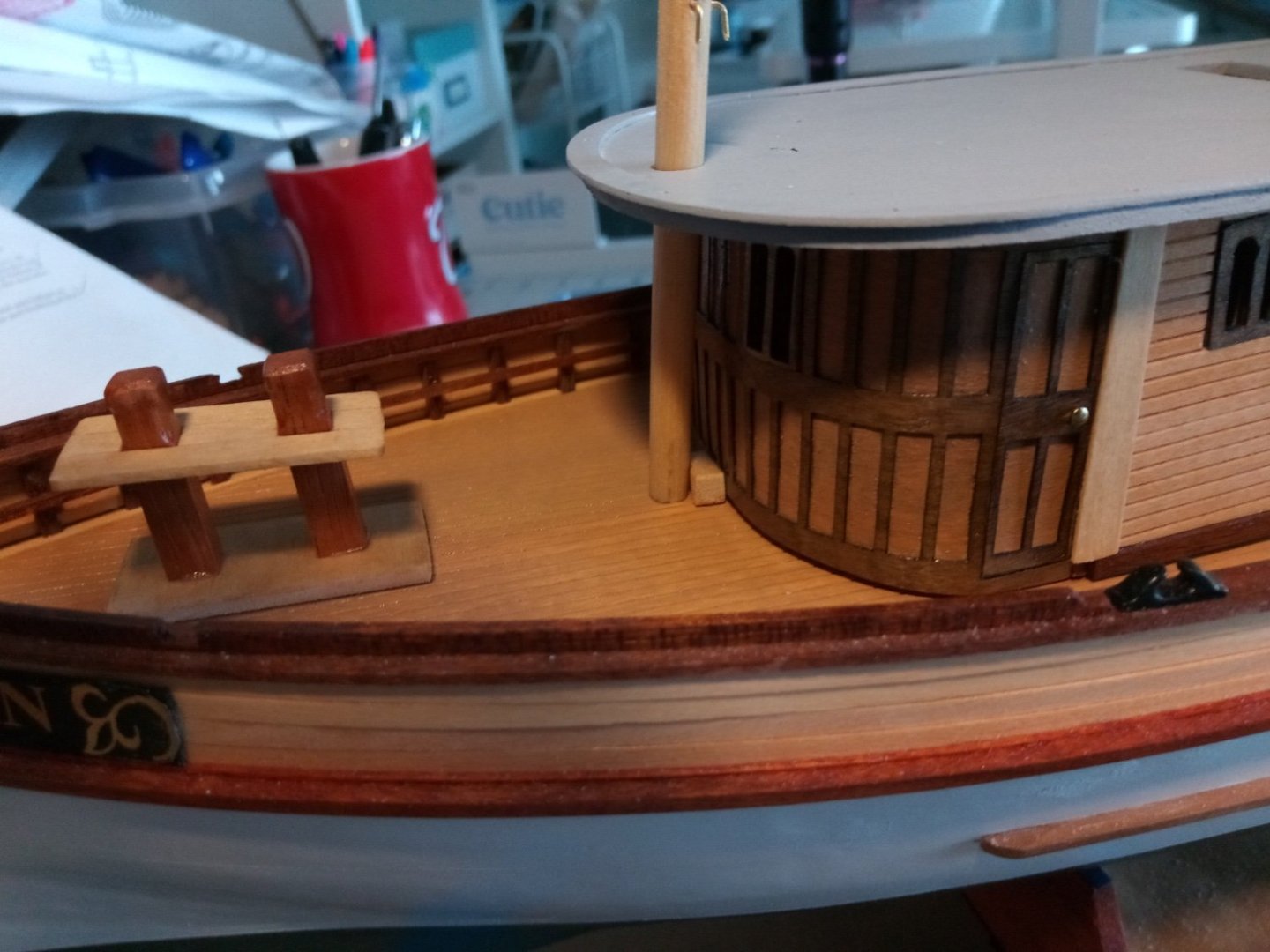
20. Upper Deck Details I did one more bathtub float test, this time with the motor running to make sure there would not be any leakage in the stern tube with the shaft rotating - everything was fine. I placed the pilothouse in place after setting up the brass railings. I got a lead on some very nice brass stanchions from RVICHMA’s SEGUIN build log. I bought 2 packs of 10 from the Age of Sail website. 24 gage brass wire fits snugly in the stanchion holes. The stack is pinned in place and the guy wires use the kit-provided copper wire with crimping tubes to fasten them: The skylight and the boat davits were easy additions: This build is almost done with just the masts, rigging and ship’s boat to go.

- 72 replies
-
- 13
-
-
-
- Seguin
- BlueJacket Shipcrafters
- (and 2 more)
-
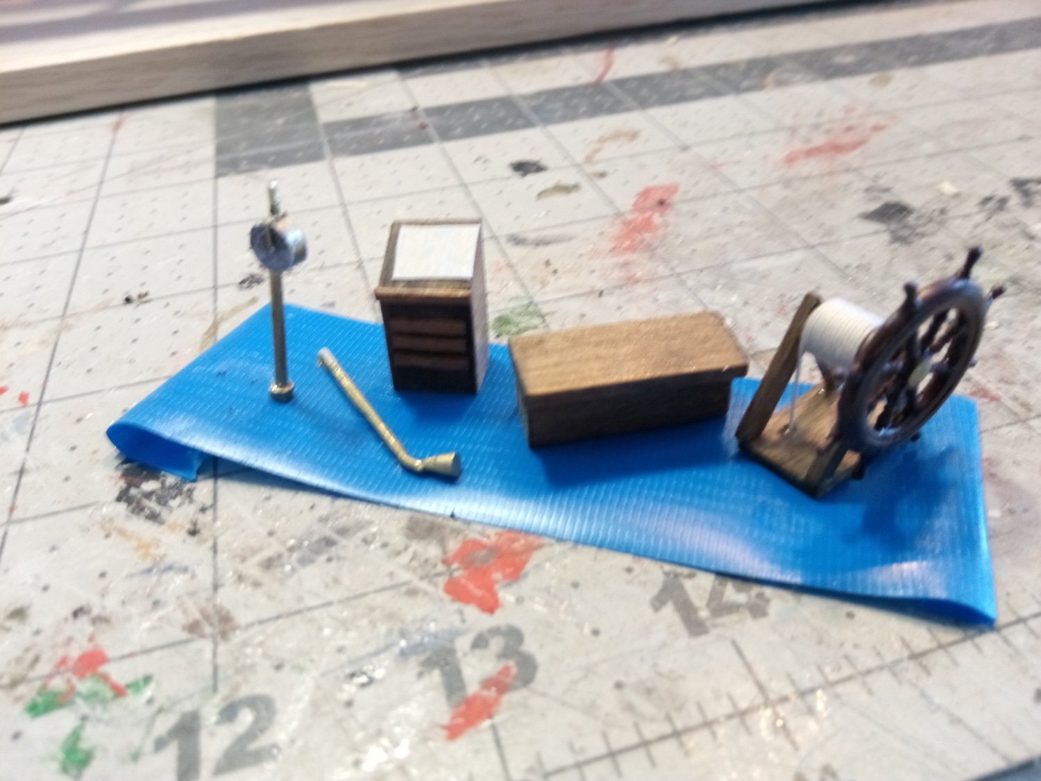
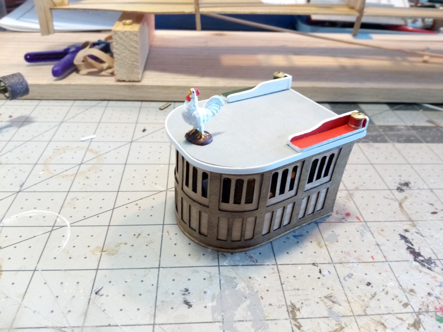
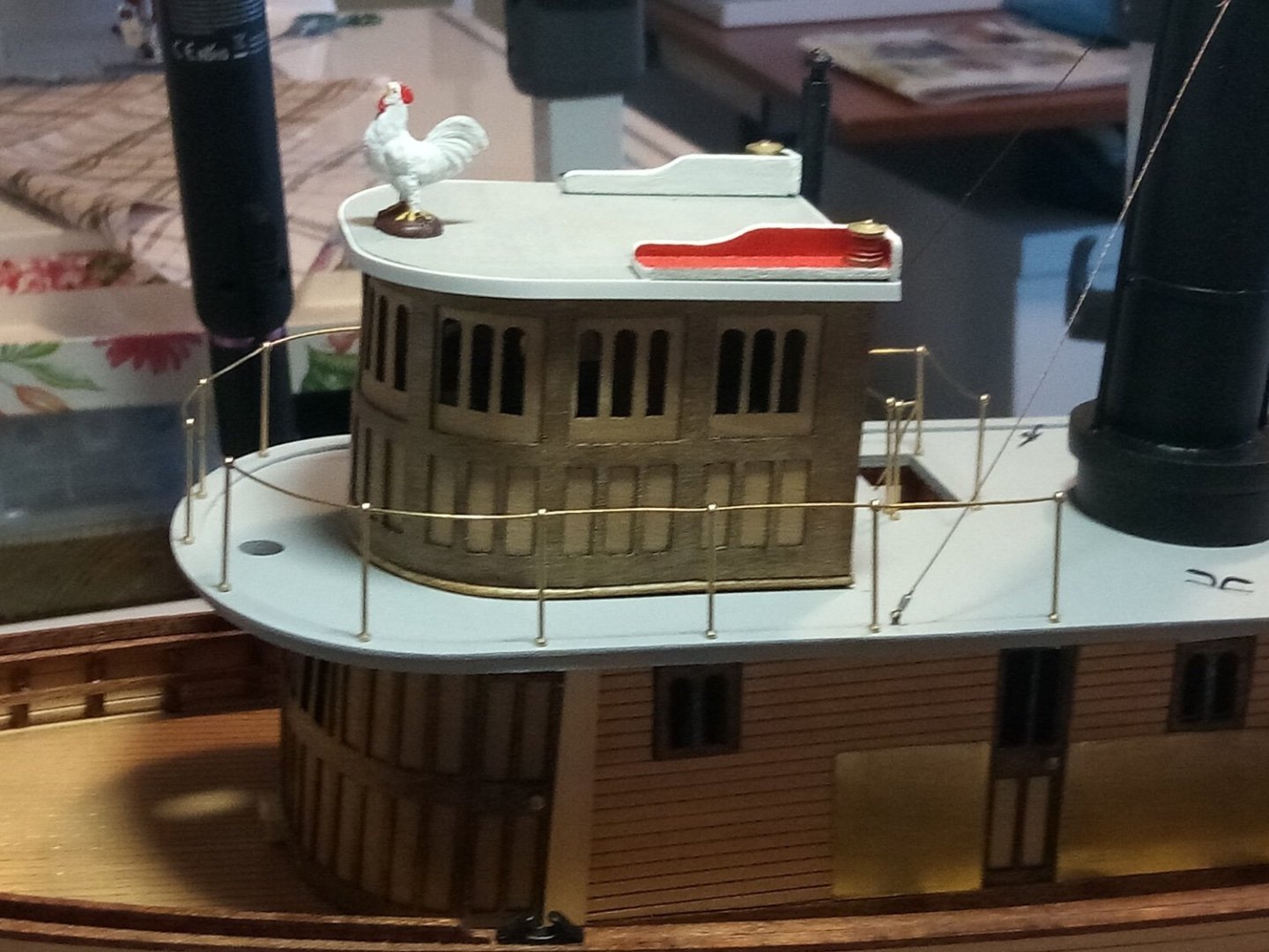
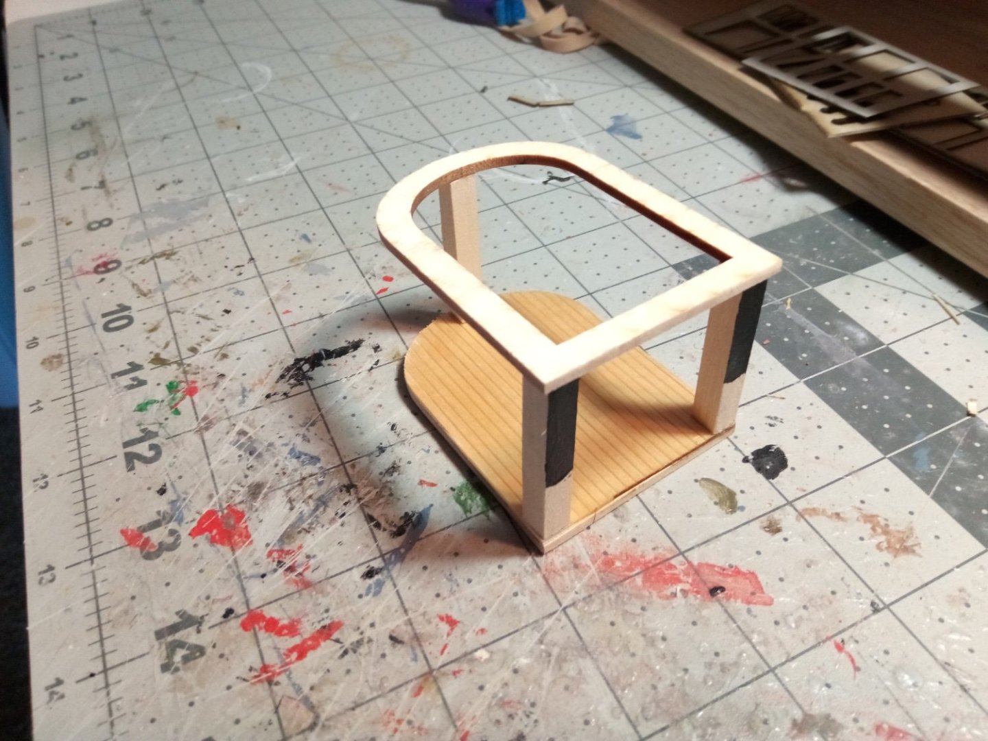
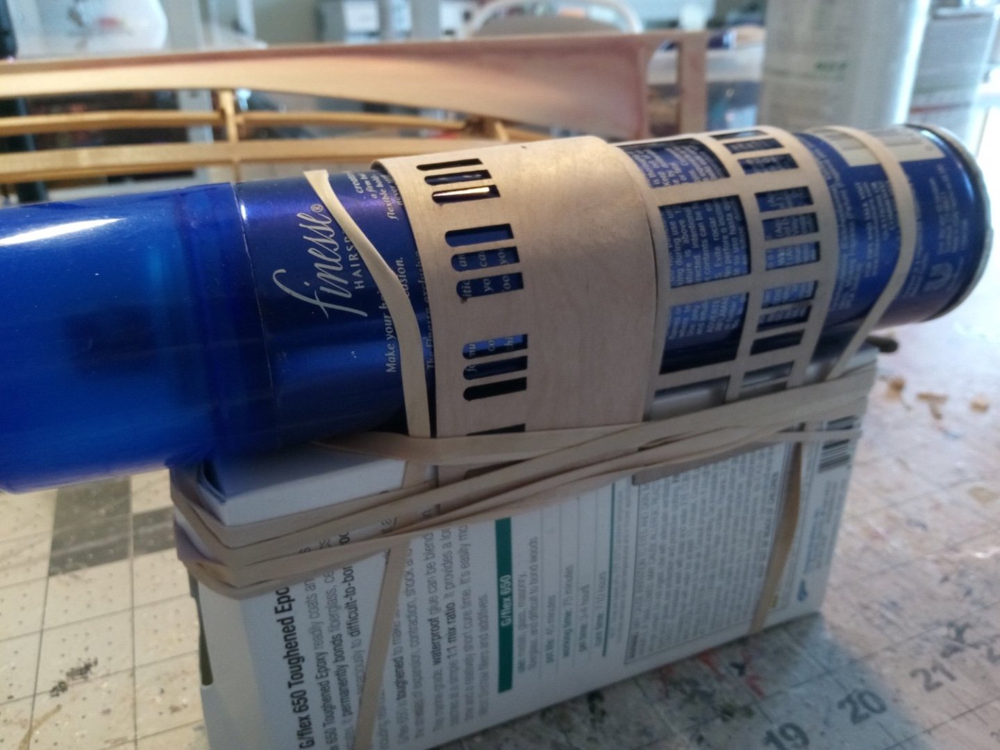
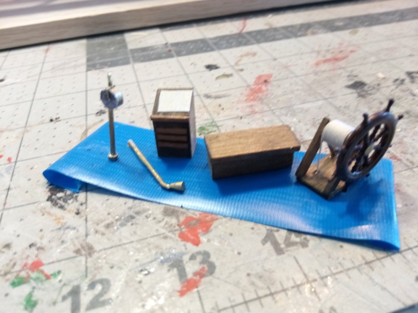
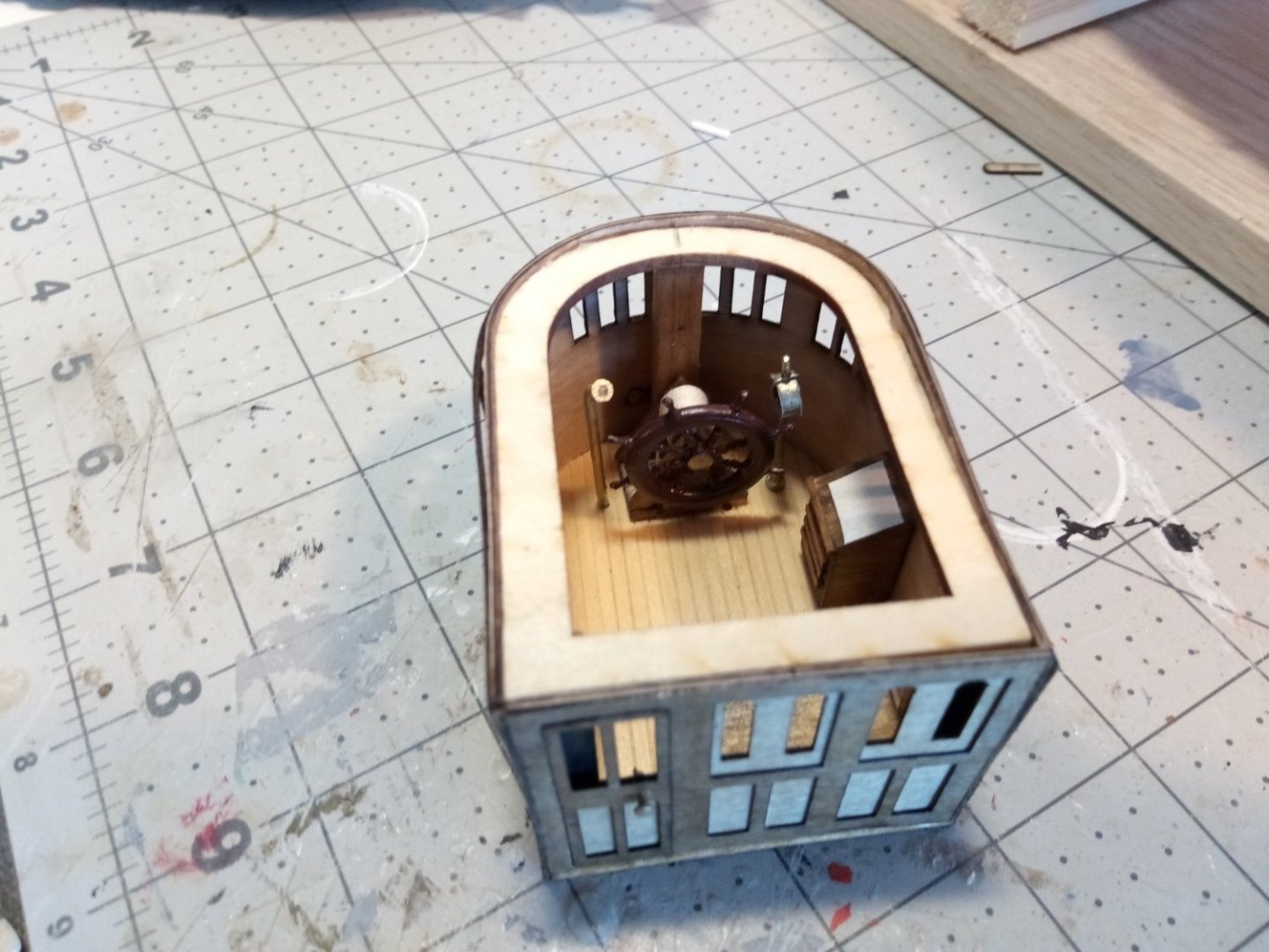
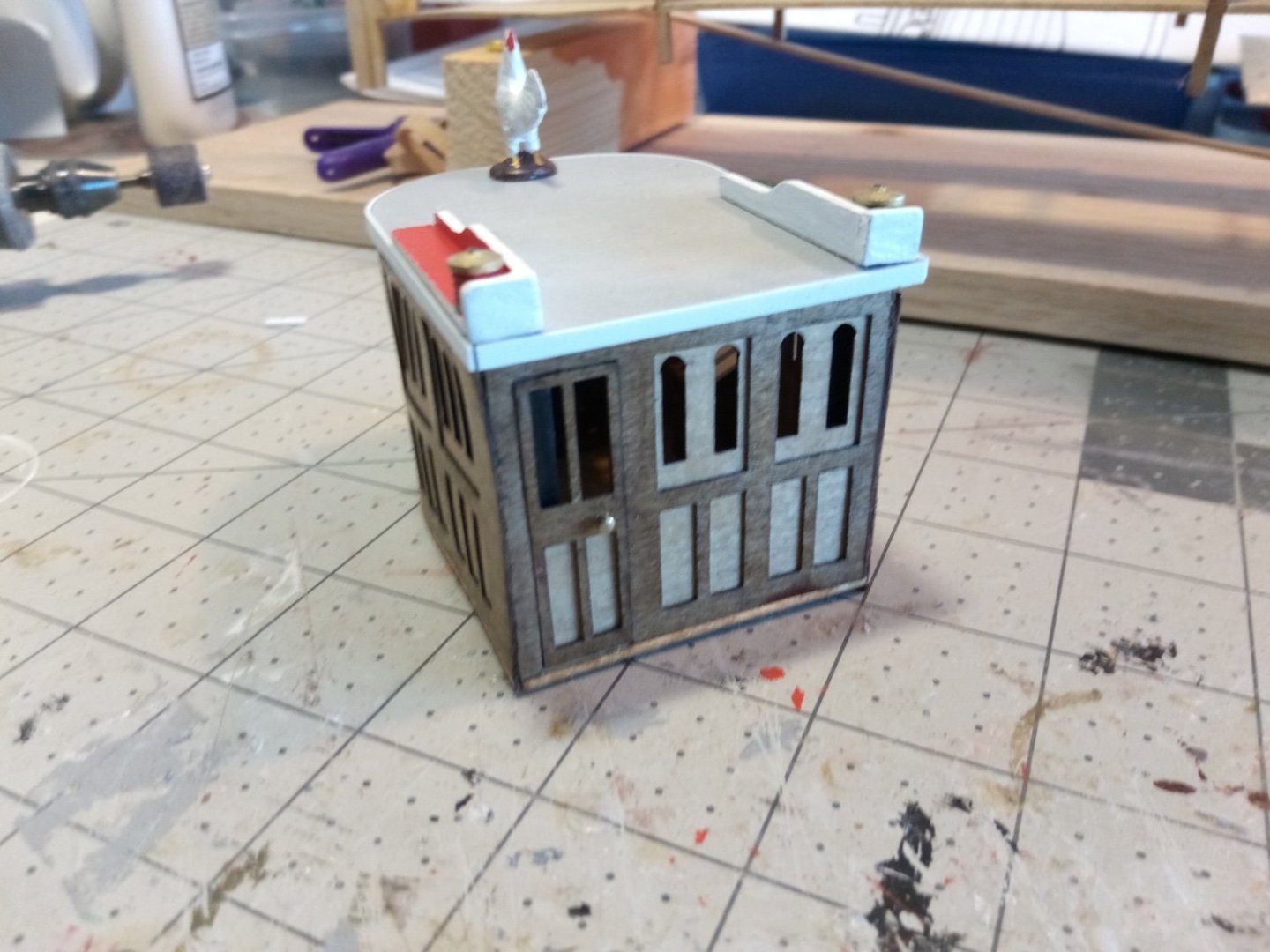
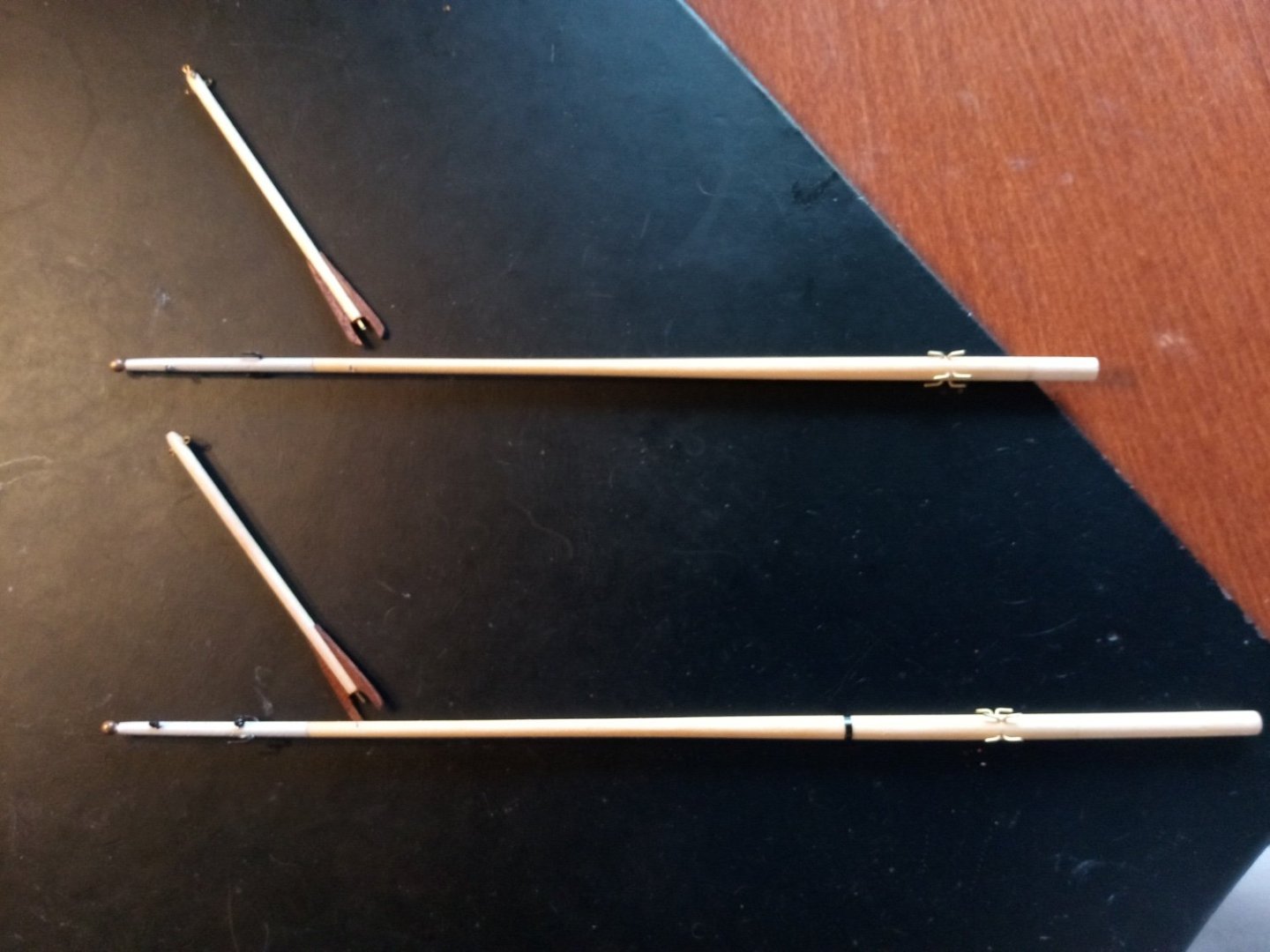
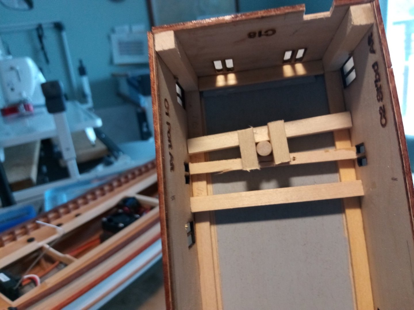
19. Pilot House and Masts The frame for the pilothouse consists of laser cut base and roof outline, joined by 3 pieces of 1/4” square stock. I added some scrap decking material to the floor. The 2 aft support columns show thru the window and door so I painted part of them black to make them less obvious. Although the instructions call for 1/4” square stock the plans show 1/8” square stock - I’m glad I went with the 1/4” , it is very sturdy which helped when it came time to bend the sheathing around the frame while glueing. To shape the 2 laminated pieces I found a spray can with the same radius as the front of the pilot house. After soaking them in hot water and ammonia I rubber- banded them in place and left them overnight: The steering wheel is britannia metal, its stand is made up of strip wood per the plans. The plans show a chart table and bench, I added a voice tube and engine order telegraph: Here is the furniture in place: And here is the completed pilothouse with the roof (and rooster) in place: As it turned out, almost all the interior details are not visible. It’s pretty dark in there and the sight lines thru the windows block everything but the top of the steering wheel, the voice tube and the bench. This would be a perfect place for putting acetate in the windows but I left them out for the sake of consistency - I had to forgo glazing the doors and windows on the lower deckhouse so that the heat from the motor and ESC would have a way to vent. The masts have been tapered and the metal work attached: The instructions call for attaching the foremast by glueing the bottom to the deck which would work fine for a static model but since this deckhouse needs to be removable I changed the attachment point to a spacer that is glued to the front of the deckhouse and will sit on the deck between the water barrel and the ice box - the mast will be glued and pinned to the spacer which is set at a width that will place the mast at the designed rake: The aft mast needs a little help securing it. The instructions call for glueing it to the hole in the roof but even for a static model that will not provide much strength when it’s time to tension the rigging since the bottom of the mast is just hanging in the air inside the deckhouse. I put a framework on the underside of the deck that will provide a good glueing surface and that also sets the mast plumb and with the proper rake:

- 72 replies
-
- 12
-
-
-
- Seguin
- BlueJacket Shipcrafters
- (and 2 more)
-
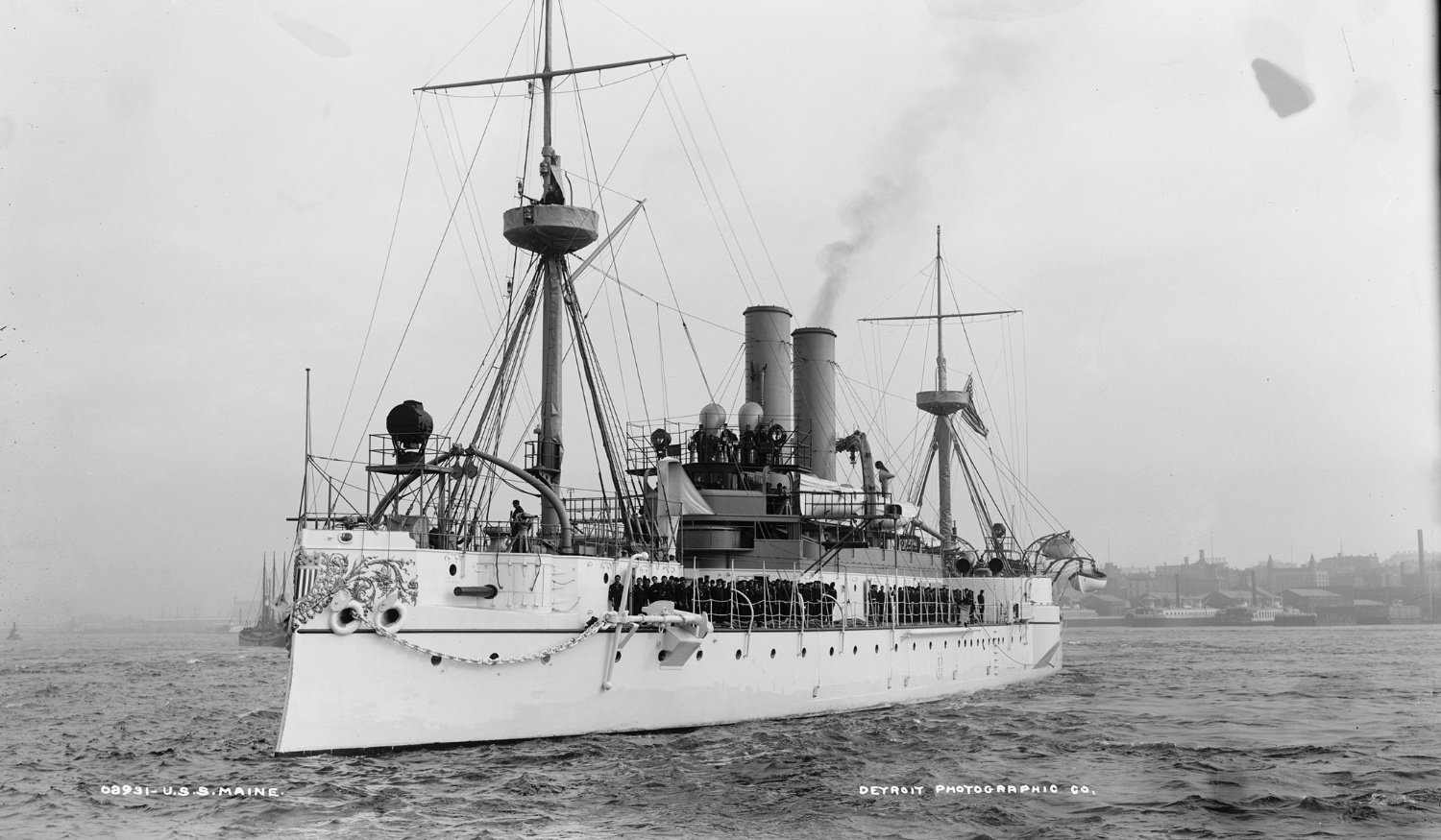
Nice rigging work! I'm at a loss figuring out what purpose the preventer serves, although the photo below shows one on each side. Any idea? BTW, if you ever get down to Maryland and DC the Maine's damaged foremast is on the seawall on the grounds of the Naval Academy in Annapolis and the main mast is at Arlington National Cemetery. Photos of both are easily Googled. Keep up the good work, I've enjoyed watching this come together.

- 166 replies
-
- 4
-
-
- Maine
- BlueJacket Shipcrafters
- (and 1 more)
-
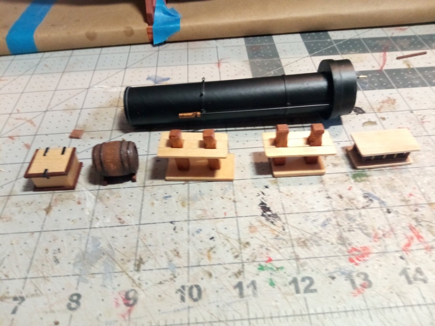
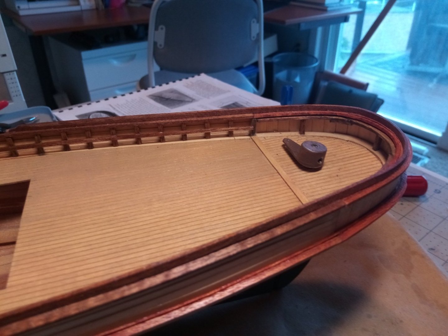
18. Steering Gear & Deck Furniture The push rod between the servo and the rudder needs small brass rod at the ends to fit into the small holes on both arms but such thin rod may bend under pressure so I used an idea I found on a RC website and used a wooden dowel for the majority of it. This model is a little unusual in that the pushrod will remain above the deck but it will not be visible since it will be inside a 3-sided box, 2 of which sat on the fantail of the real SEGUIN to protect the steering ropes. The box hiding the pushrod and the fantail grating will be spot glued with white glue so I can remove them if needed. The deck furniture is done, with the exception of the boat. The fore and aft bitts, the ice chest, the stack and the skylight are per the plans. The kit provides a resin piece for the water barrel but I’ve had several wooden ones from Model Expo in my stash since my first build, as it turns out they are a perfect match for the plans so I used one. Next up will be the Pilothouse.


- 72 replies
-
- 14
-
-
-
- Seguin
- BlueJacket Shipcrafters
- (and 2 more)
-
This is an impressive project - more a scratch build than a kit one. Your Charles Notam is one of the most amazing builds I've seen on this site - which has plenty of models that just leave me speechless.
-
Hi Ian, Yes it is a mini-servo on the rudder, I got a pack of 10 of them online for about $20, hopefully it will work because a larger one I have won't fit in that spot. If it does burn out after a while at least I have plenty of spares. As far as the motor goes I don't know if it is brushed (I threw the box out and I'm a total RC newbie), it is geared. The Washburn does look like a nice kit, there is a decent build log for it over at https://www.rcgroups.com/forums/showthread.php?1558895-Building-the-George-W-Washburn
- 72 replies
-
- 1
-
-
- Seguin
- BlueJacket Shipcrafters
- (and 2 more)
-
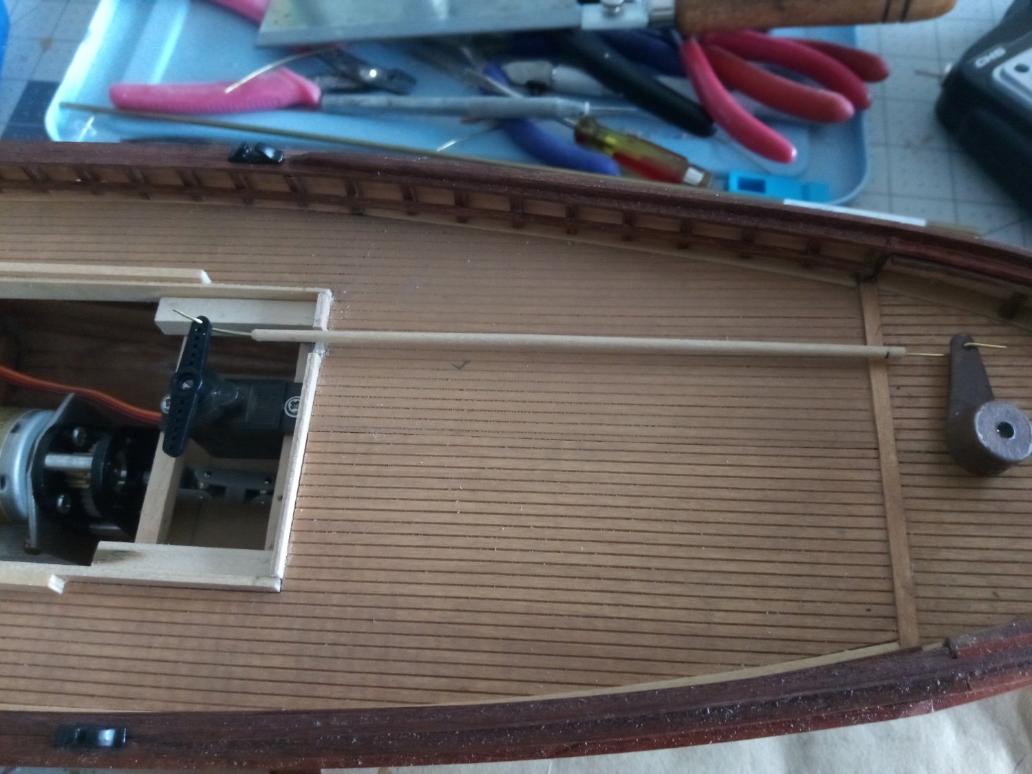
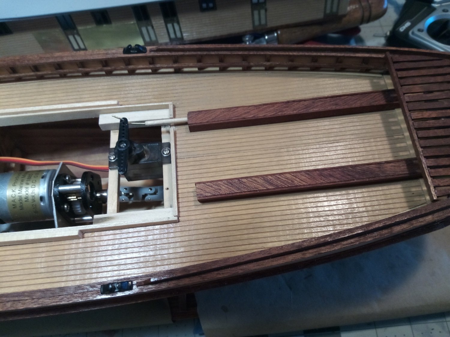
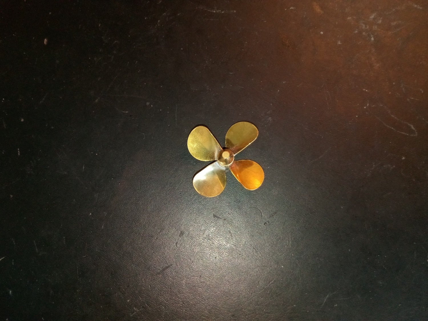
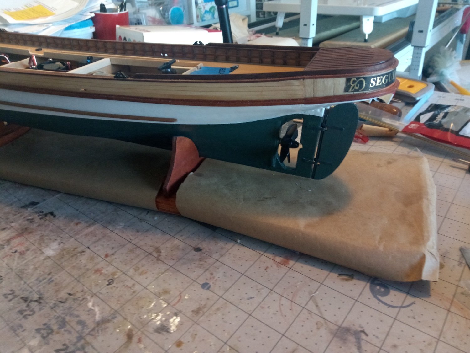
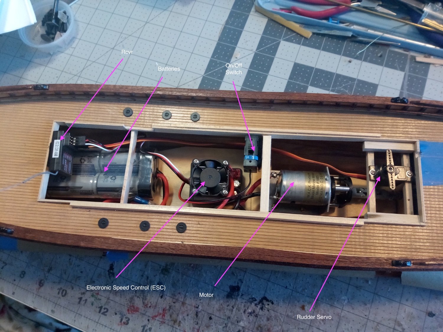
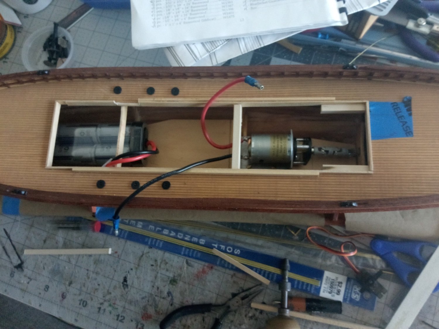
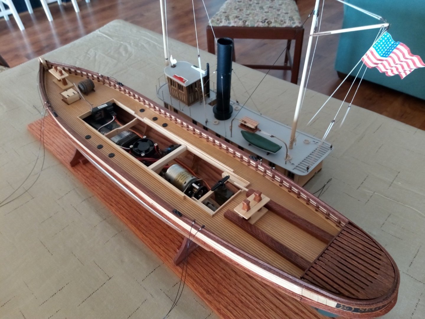
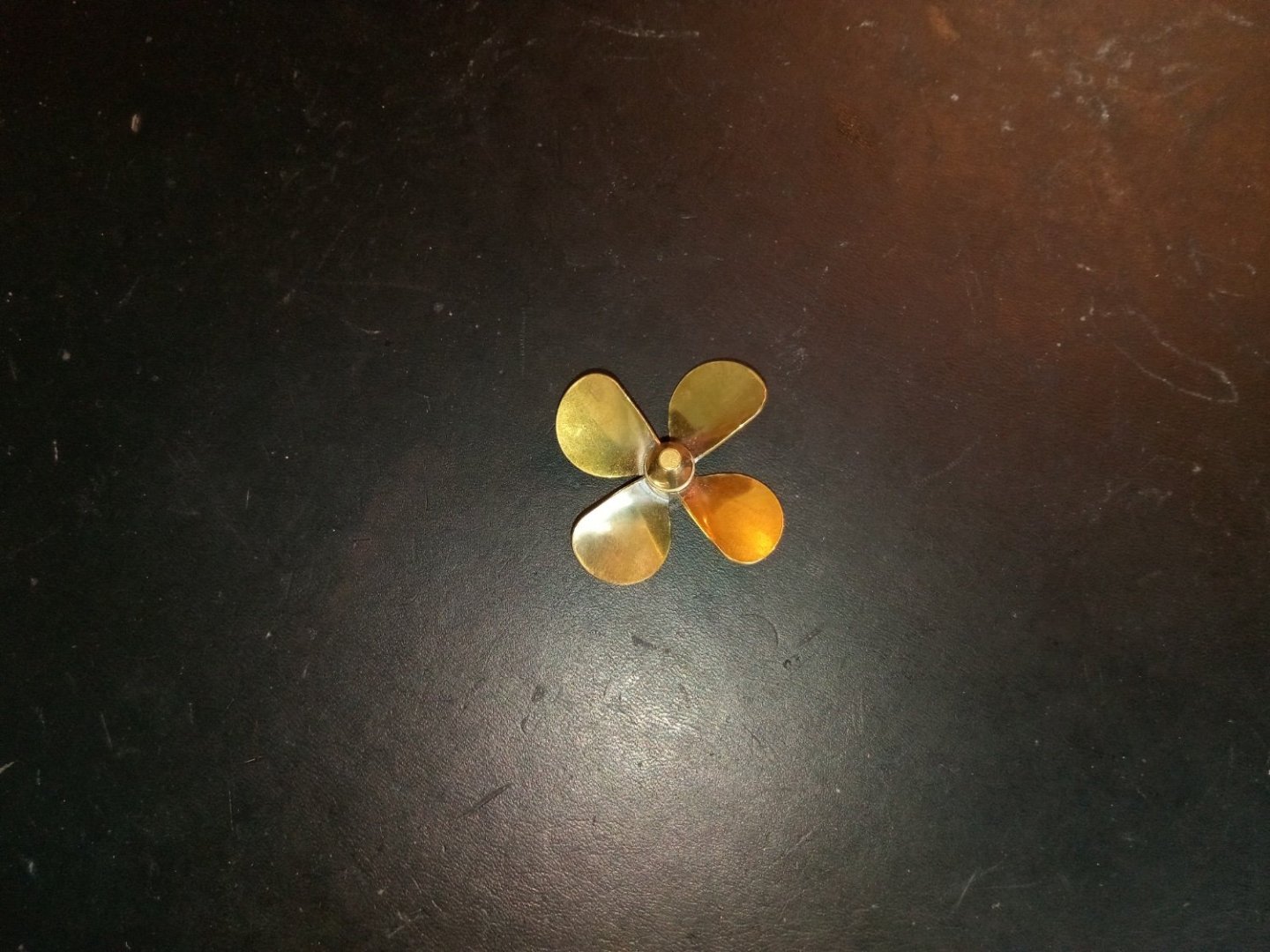
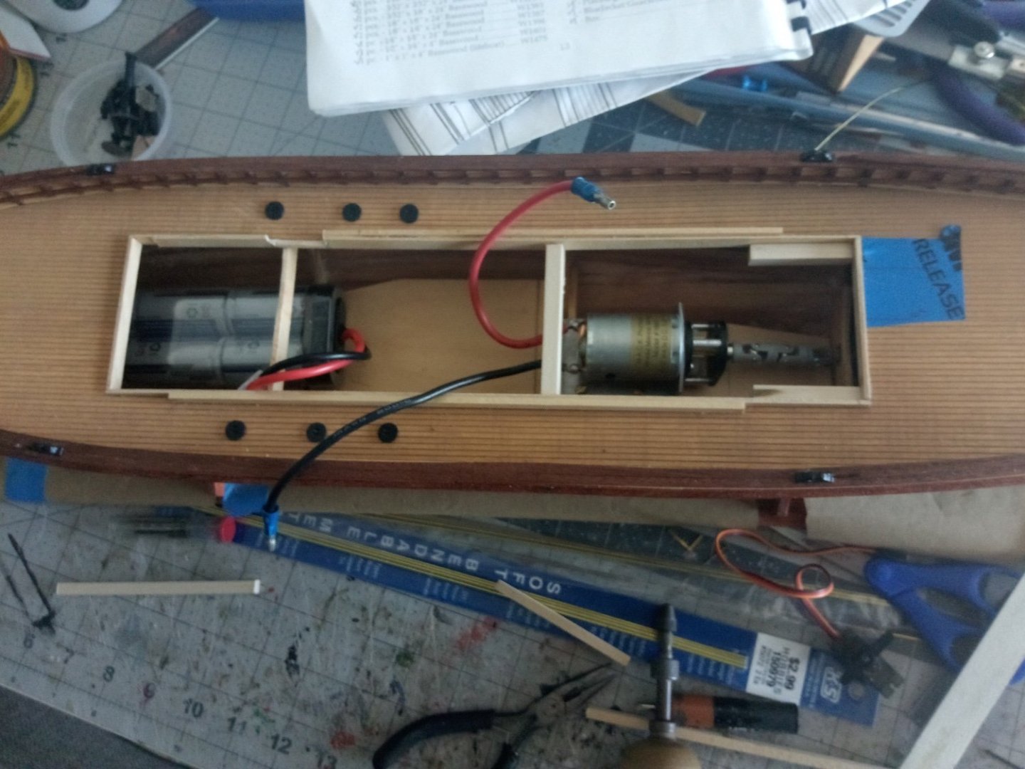
17. Installing Ballast and the RC Gear Bedford posted a reply a little ways back recommending that I ballast down the model to its waterline and let it float in the tub for a few hours to make sure there are no leaks. It was a good suggestion so I followed it. I went to my local Bass Pro outlet and bought a selection of different sizes of lead fishing weights. I ended up using about 3/4 lb of the weights, all of them in the aft 1/3 of the hull since there is a pronounced “squat” on this hull - the waterline and the keel are no where near parallel. Just like on modern tugs, they wanted to get the prop as deep as possible to generate thrust, not bubbles. I ended up with just under 1/2 lb of weight in the aftermost section near the rudder tube and the rest went under where the motor will sit. I could only fit one of the two NiMh battery packs I ordered but even if there was room for the second pack there is not enough reserve buoyancy to support it - just one pack took care of bringing the bow and midships area down to the waterline. The bathtub test worked fine - thank goodness. With that out of the way it’s time to start installing the RC gear. The first thing I had to do was something I did not want to do. The biggest threat to running this model on my lake will not be wakes from real boats but one of these guys (the fish not the geezer - that's not me BTW): There are a ton of Largemouth Bass in my lake, including a few big ones under my dock. They weigh 3-5 lbs, move fast and strike vertically at prey on the surface, including baby ducks (all together now “Oh No!! Not baby ducks!!) One of the most effective lures for catching them (bass, not ducks) uses brass blades that rotate as you retrieve it so it looks almost identical to what this beauty would look like while running: So after sanding off the protective coating and adding spray paint my prop is now a boring black: The motor was mounted to its pad with screws. Aligning the motor shaft with the prop shaft was easy to do visually athwartship but vertically took a combination of a small mirror and my finger to check for alignment as I turned the screw. The battery pack is velcroed to its pad so it can be removed if needed but I plan on recharging it in place. The ESC is also velcroed so it can be removed if I need to remove the battery pack (for a relatively large model there really isn’t all the much space to work with inside the hull). Since the rudder servo will also experience torque it’s mounted with screws. The servo is placed so that its arm and the arm on the rudder stock align fore and aft. The last item to add was the receiver - I placed it as far forward as possible to minimize electro-magnetic interference from the motor and ESC. Placing it there also allows the 3 inch antenna to project vertically up into the deck house for (hopefully) better reception. Next up will be installing the pushrod between the servo and the rudder.


- 72 replies
-
- 11
-
-
- Seguin
- BlueJacket Shipcrafters
- (and 2 more)
-
Thanks for all the kind words everyone - it has been "a real trip" to use a term from my youth. Double-planking would be a good idea.
-
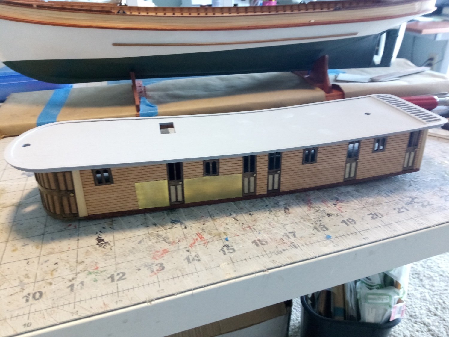
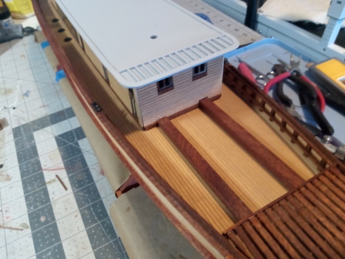
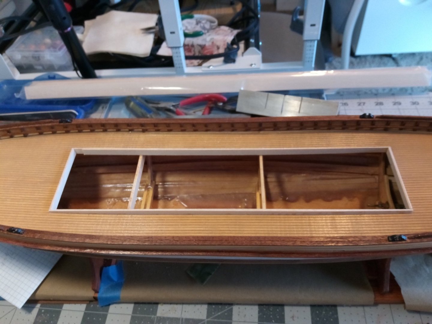
16. Lower Deckhouse (cont) The instructions call for removing the tops of frames 2 and 3 but I left them on to avoid any spring back from affecting the hull seams - I think I can work around them installing the RC gear. The instructions also call for installing a coaming around the deck opening “3/8” wide out of 1/16” basswood”. I did not understand why they needed to be so large so I made mine about 1/4” high with about 1/8” above the deck: The pieces of the deck house went together without a problem. In addition to the 1/4” square stock added to the aft corners to brace them I also added them to the forward corners. 1/16” by 1/4” stiffeners have been added to the top edges, they also serve to increase the glueing area for attaching the roof. I marked where the door opening will be have to cut out on the starboard (far) side for the stairwell: The waterway along the edge of the roof is a piece of laser-cut thin wood. The roof attached to the deckhouse without any need of soaking - despite the sheer of the deckhouse. The instructions call for making the stairs out of strip wood fitted into slots. That would look great but I don’t have the tools or the skills to pull that off so I used a piece of 3/8” by 5/8” strip wood cut into lengths, each 1/4” longer that the previous one and then glued the them in a stack and used the scribed decking material to make the sides of the stairwell: When I fitted the completed deckhouse to the deck the coaming provided a snug fit fore and aft but there was little contact on the sides so I tried various thicknesses of strip wood to increase the width of the coamings until I got a good fit all around - good enough that when I turn the hull upside down the deckhouse stays in place. I was pleasantly surprised at how well the laser cut sides match the sheer of the deck - it is a great fit that does not need any additional strips along the bottom to hide any gaps.
- 72 replies
-
- 14
-
-
-
- Seguin
- BlueJacket Shipcrafters
- (and 2 more)
-
The photo showing the boiler front with the fire doors right under a cabin floor goes a long way to explaining why those boats were such fire traps! This build is coming along nicely, keep up your typically good work!
- 58 replies
-
- 2
-
-
-
- Robert E Lee
- Amati
- (and 4 more)
-
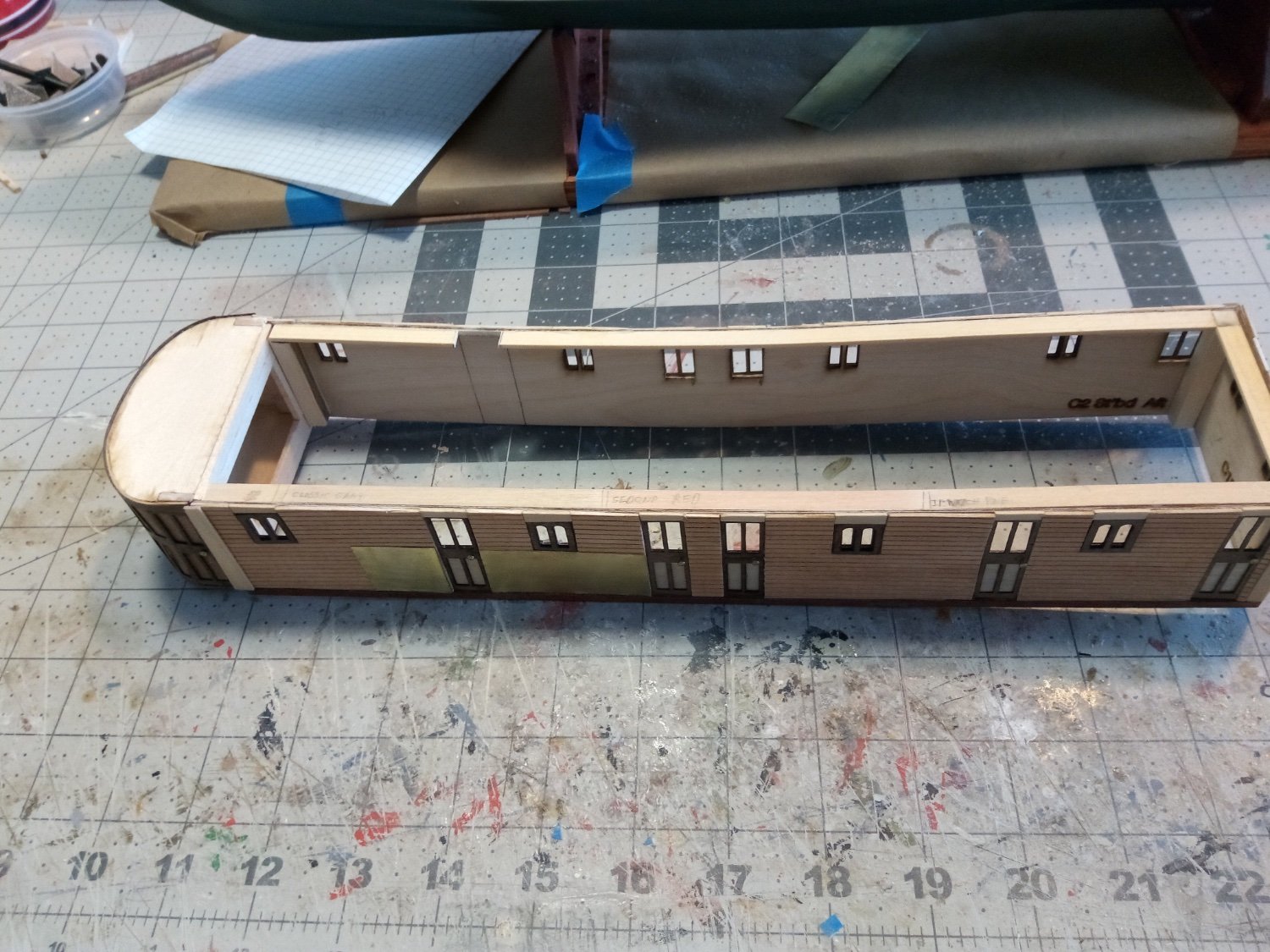
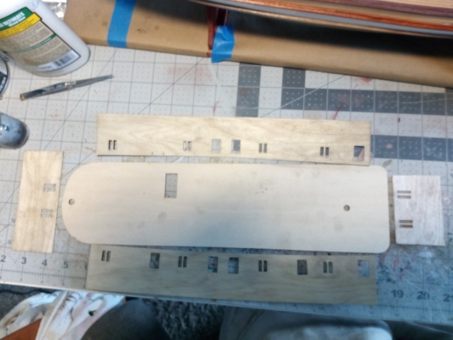
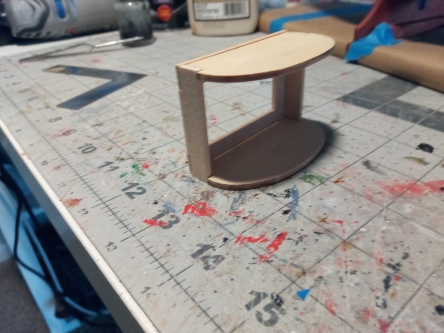
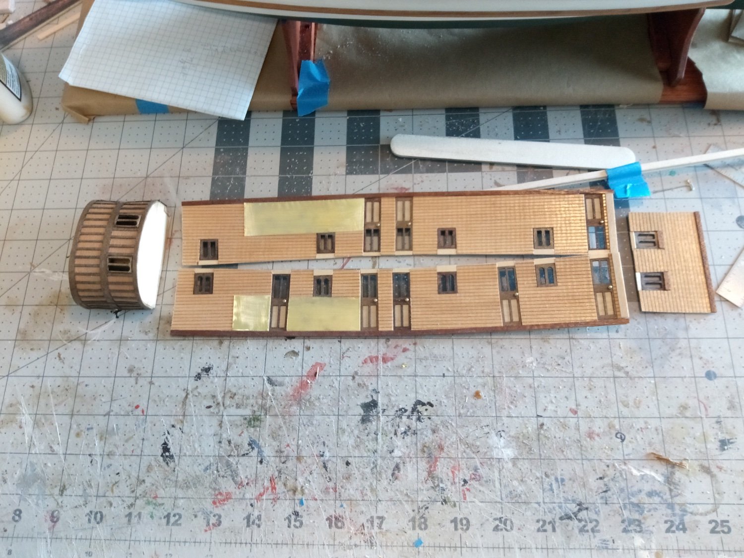
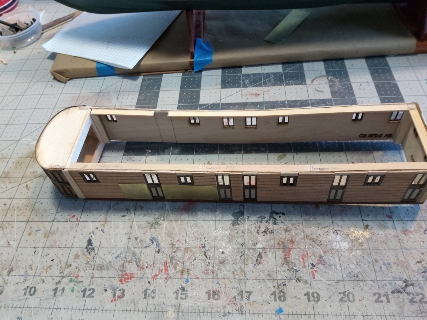
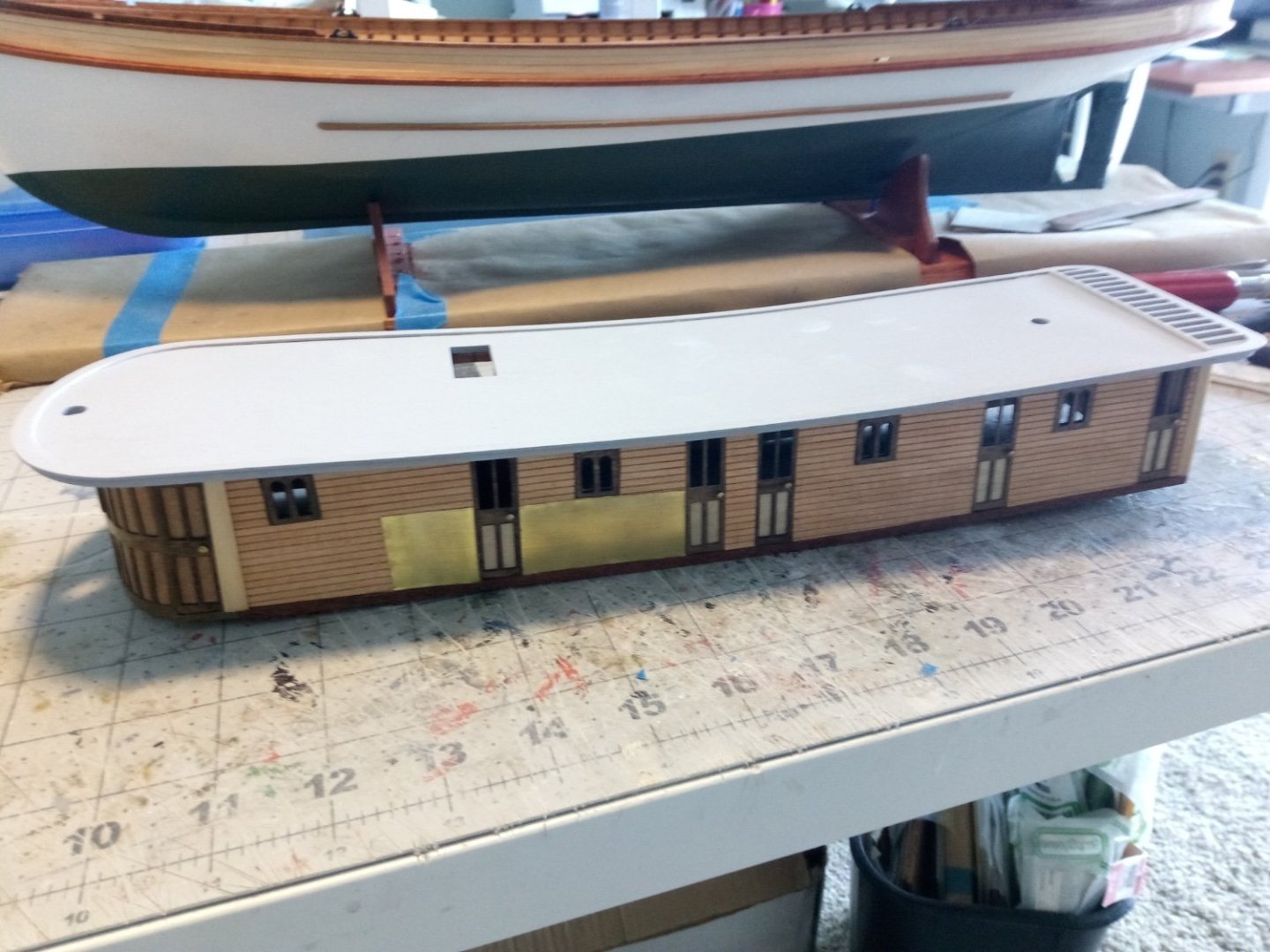
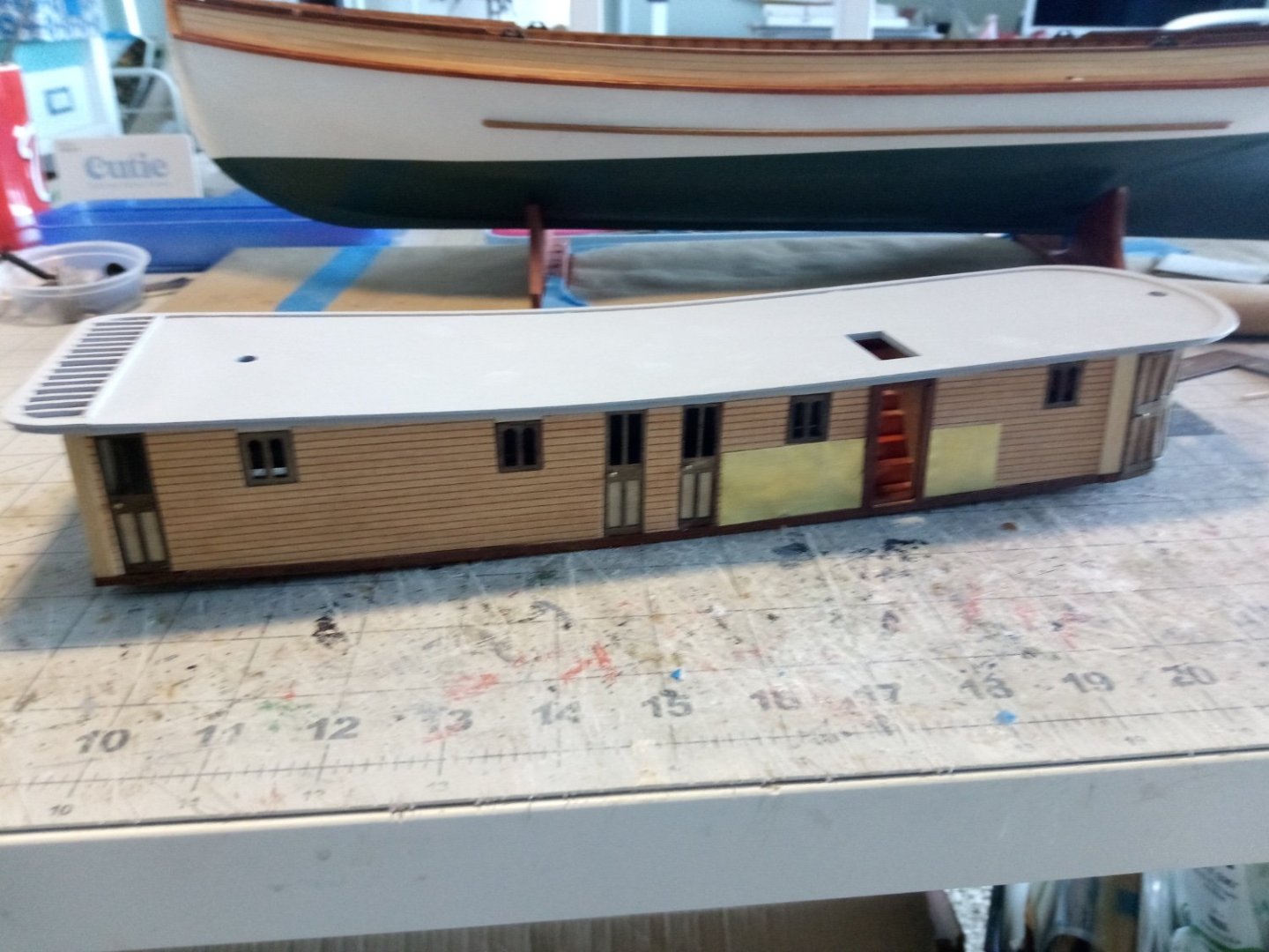
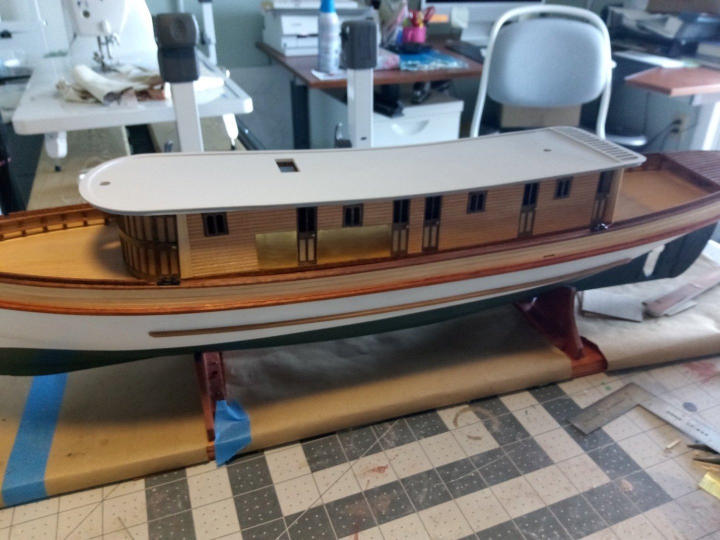
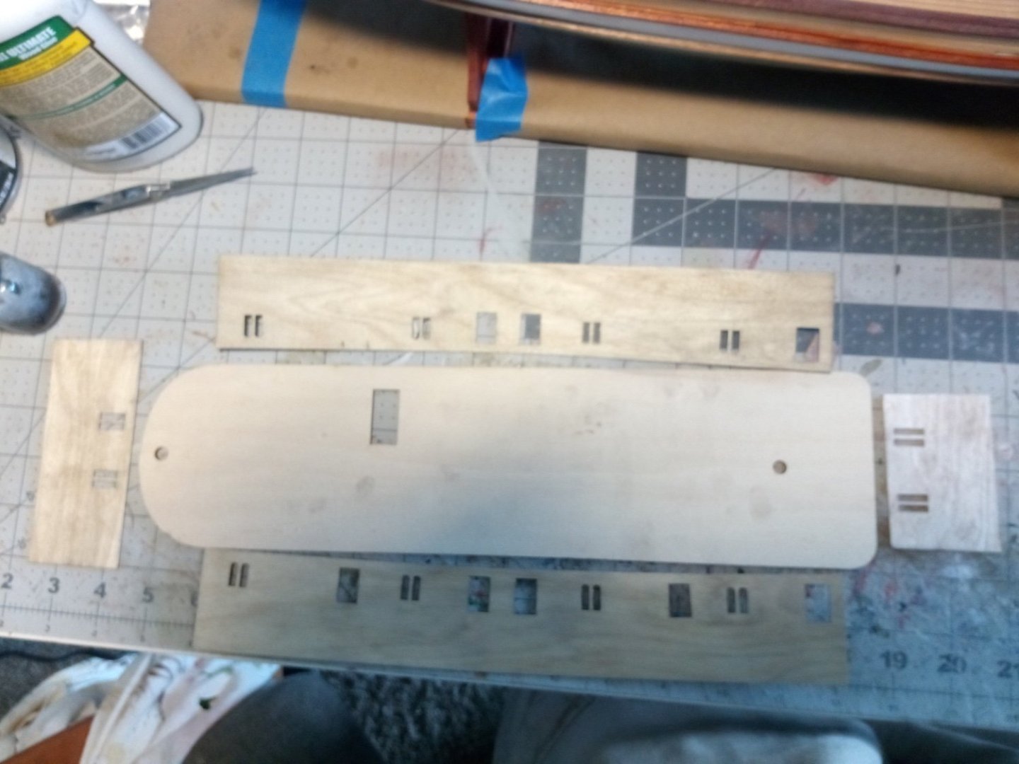
Post 15 Lower Deckhouse The kit provides laser cut sides, rear bulkhead and roof. The semi-circular front is made up of strip wood covered with 2 laminate pieces. There are 12 windows in the deckhouse and the kit provides 20 window frames. Since the 2 forward windows do not get frames that leaves enough for 2 frames per window, which is good, because if 2 of them are stacked they look better when surrounded by the scribed sheeting. A minor point that could be easily missed: There is a door on each side of the curved front piece, both at the aft edges. The only way to know that is to notice the door knobs on the plans. I added door knobs to all the doors using the heads of some brass finishing nails. The frame for the front went together well but I had trouble bending the inner piece - not so much bending it as getting the bend to remain after the soaked wood had dried out - it returned to a basically flat condition. I think the problem was due to the wood provided being plywood so I used it as a template to make another piece out of 1/32” sheet basswood. The basswood bent easily and retained its shape after soaking. The top piece bent without a problem. The instructions call for assembling the deckhouse sides into a box and then adding the scribed wood sheeting and brass (shielding near the coaling scuttles) but I thought it would be easier to measure and fit those while the pieces were laying flat. The built-in curvature to the top and bottom of the sides in order to fit the shape of the deck is readily apparent (and welcome). The brass does not look good in a photo but in “real life” it looks fine:


- 72 replies
-
- 8
-
-
- Seguin
- BlueJacket Shipcrafters
- (and 2 more)
-
Your photo reminds me of something unexpected I recently learned - the MinWax stains you show in the lower right of your photo match what I've encountered coming straight out of the can but if I stirred them (not shaken) the colors change dramatically, e.g the Ipswich Pine goes from the light transparent yellow to a solid dark-medium brown. The can directions make no mention of either stirring or not stirring it prior to use. I've decided to leave well enough alone- that way I know that I'll get something that looks like the color on the label. Keep up the good (and fast) work - she is coming along great!
- 58 replies
-
- 1
-
-
- Robert E Lee
- Amati
- (and 4 more)
-
Looks "bigger than the average bear" as Yogi would say. Glad you didn't decide to take the trash out early that morning or this could have ended up being a very short build log.
- 58 replies
-
- 3
-
-
- Robert E Lee
- Amati
- (and 4 more)
-
Thanks Bedford, Appreciate all the insight into glassing and epoxy. I will take onboard your suggestion to ballast her down in the tub and leave it there for several hours.
- 72 replies
-
- 2
-
-
- Seguin
- BlueJacket Shipcrafters
- (and 2 more)
-
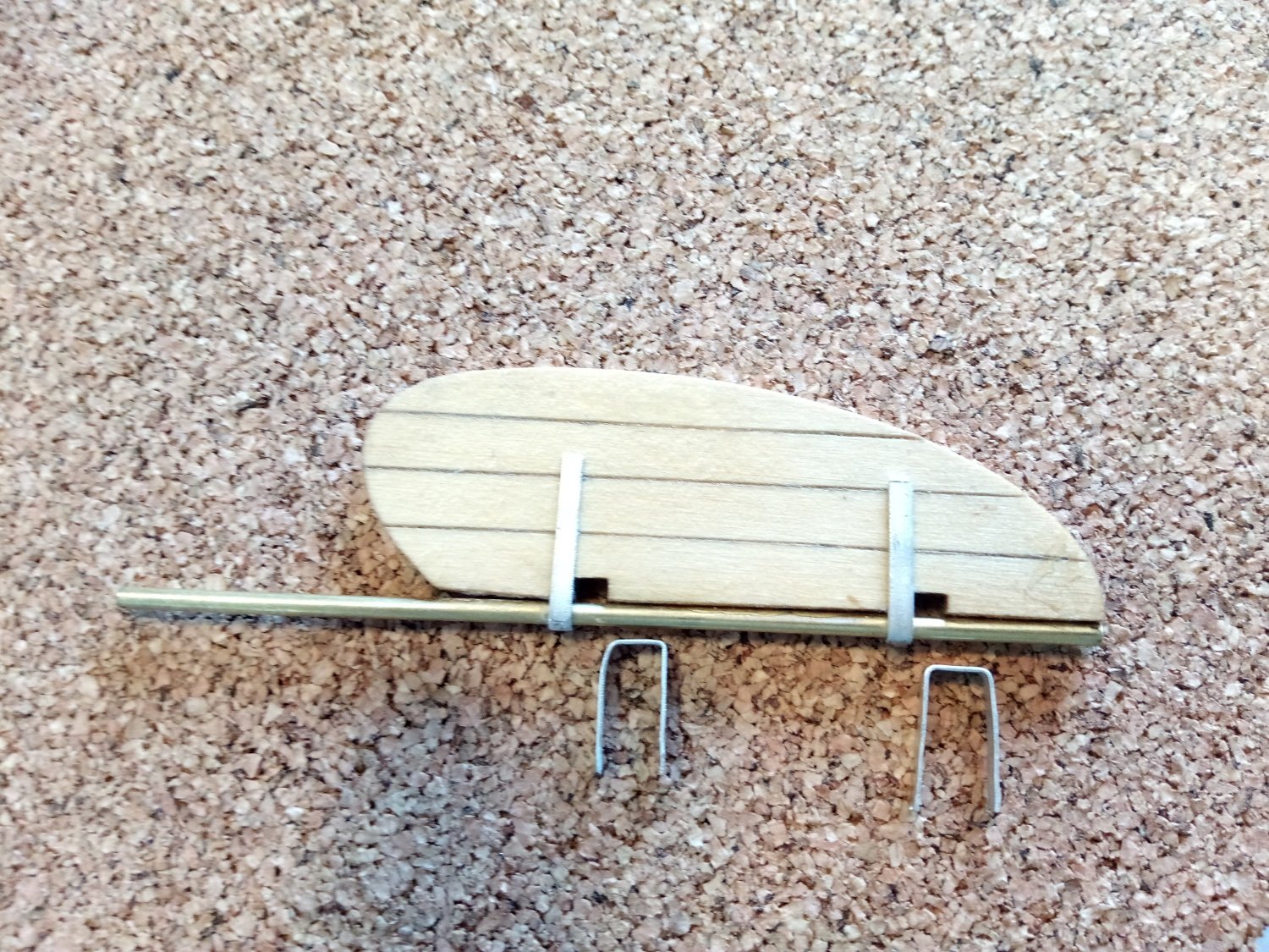
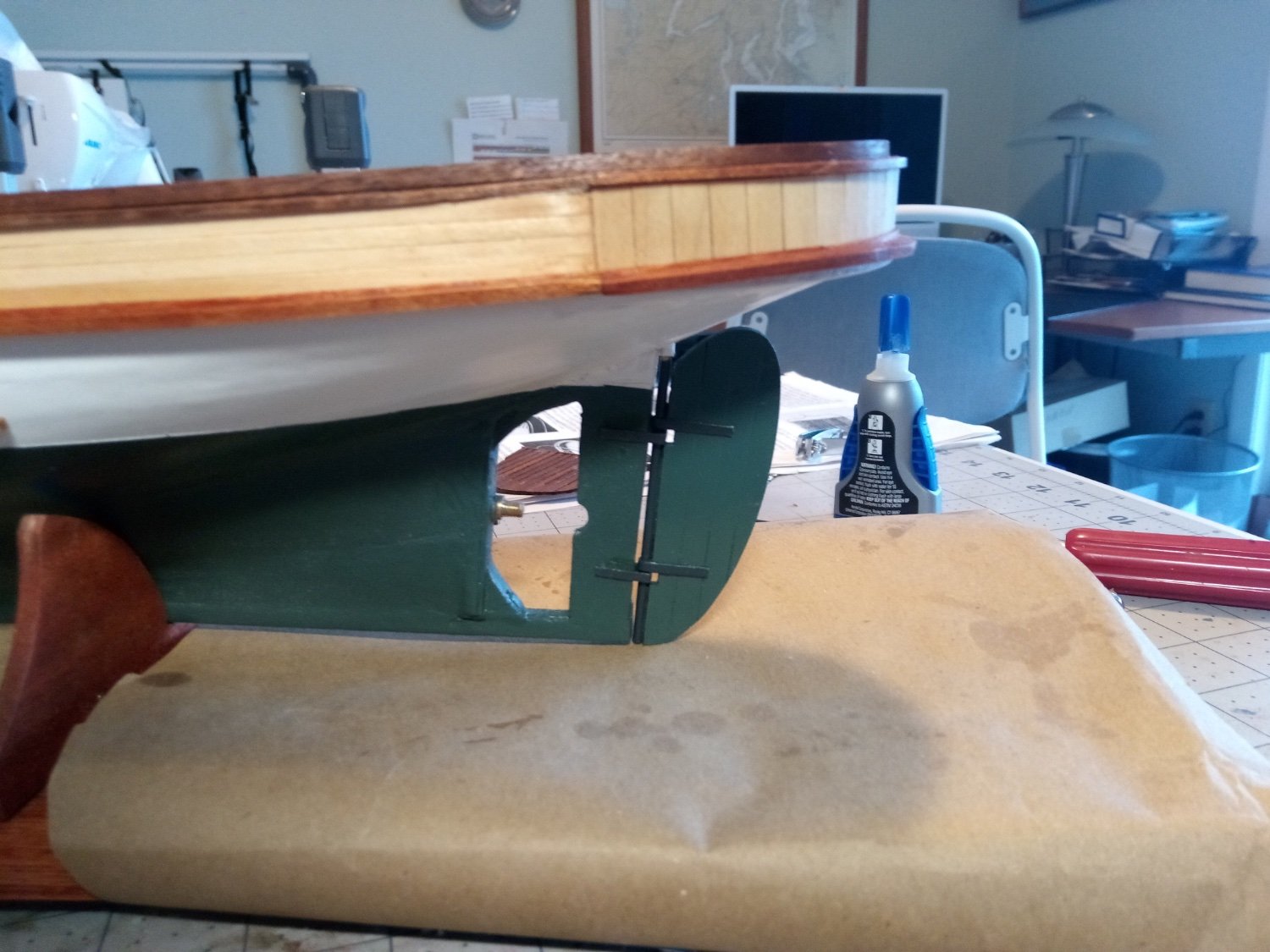
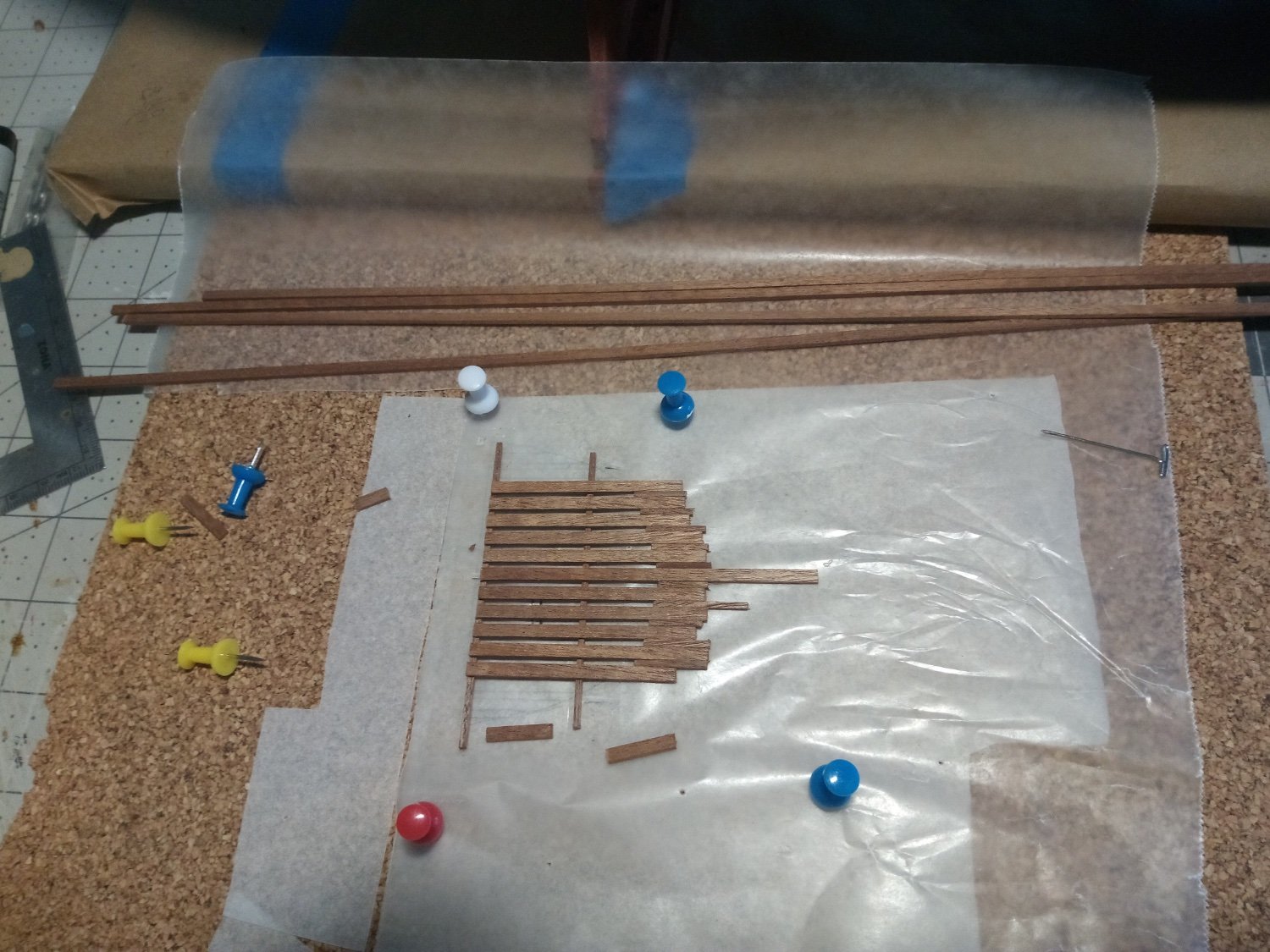
Post 14: Rudder and Transom Grating A lot of outside distractions have kept me away from the build for a while but I finally got back to it. The rudder is a laser cut piece. I scribed the plank seams with an awl. Then instructions call for making the gudgeons and pintles out of brass strip cut from a supplied sheet. Since I had some Brittania strip material on hand of the right size I just used that. Gotcha note: The photo of the rudder in the instructions is wrong - although I can never keep straight which are the gudgeons and which are the pintles that doesn’t matter, the ones attached to the rudder go above (on top of) the ones attached to the hull - the photo has them backwards but the plans are correct. I ended up buying a rudder arm from Dumas, P/N 3504, which will fit over a 1/8” O.D. tube, which in turn fits snugly over the kit supplied 3/32” brass rod used for the rudder post. The arm is secured with a set screw. Up next was fabricating the grating that covers the transom area. I traced the shape from the plans which was a fairly close fit for my transom. The strip wood was then assembled on top of the tracing: Then it was just a matter of a little sanding around the edges, test the fit, and repeat until it fit. This is just dry fit, I’ll probably secure it with double-sided tape so it can be removed for access to the rudder arm. Next up will be starting the deck house.


- 72 replies
-
- 8
-
-
- Seguin
- BlueJacket Shipcrafters
- (and 2 more)
-
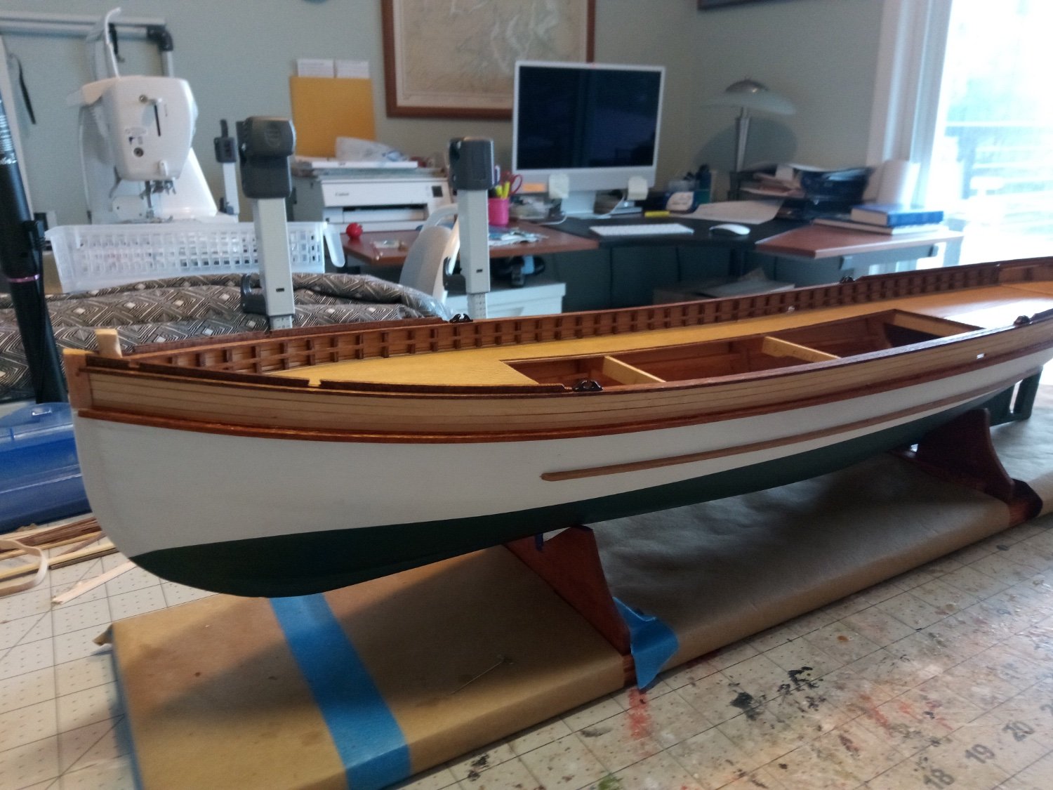
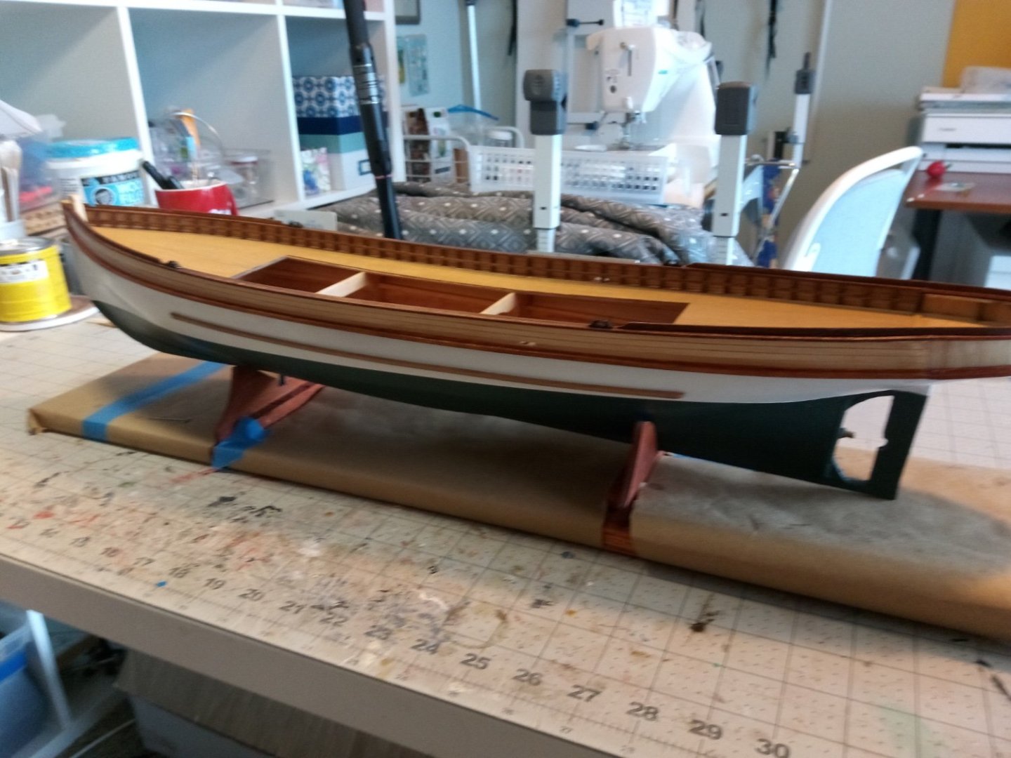
13. Rub Rails The upper and lower rub rails are made from 3/32” square stock. I thought the lower rails would be a problem since they had to be glued to a painted surface so I ran a test on the underpart of the transom where it would be out of sight. It was a problem - 5 minutes after glueing a small piece with CA it came off easily. I tried again and left it for an hour - still not a firm hold. The 3rd time I left it for about 5 hours - success. Although the instructions don’t mention it, the plans show that the upper rail rests on a slightly wider (1/8”) piece of thin wood with both bottom edges aligned, it serves a useful purpose in that it covers the seam between the hull and bulwark planks. I used some 1/8 x 1/32 strip for the underlay. Here the first piece has been attached near the stern: After the upper rail was added everything that has been added since the hull was painted was given a coat of wipe-on poly, it doesn’t make much difference in the appearance of the basswood decking or planking but it does make the mahogany stand out: Next up will be the rudder and rudder post.
- 72 replies
-
- 13
-
-
- Seguin
- BlueJacket Shipcrafters
- (and 2 more)
-
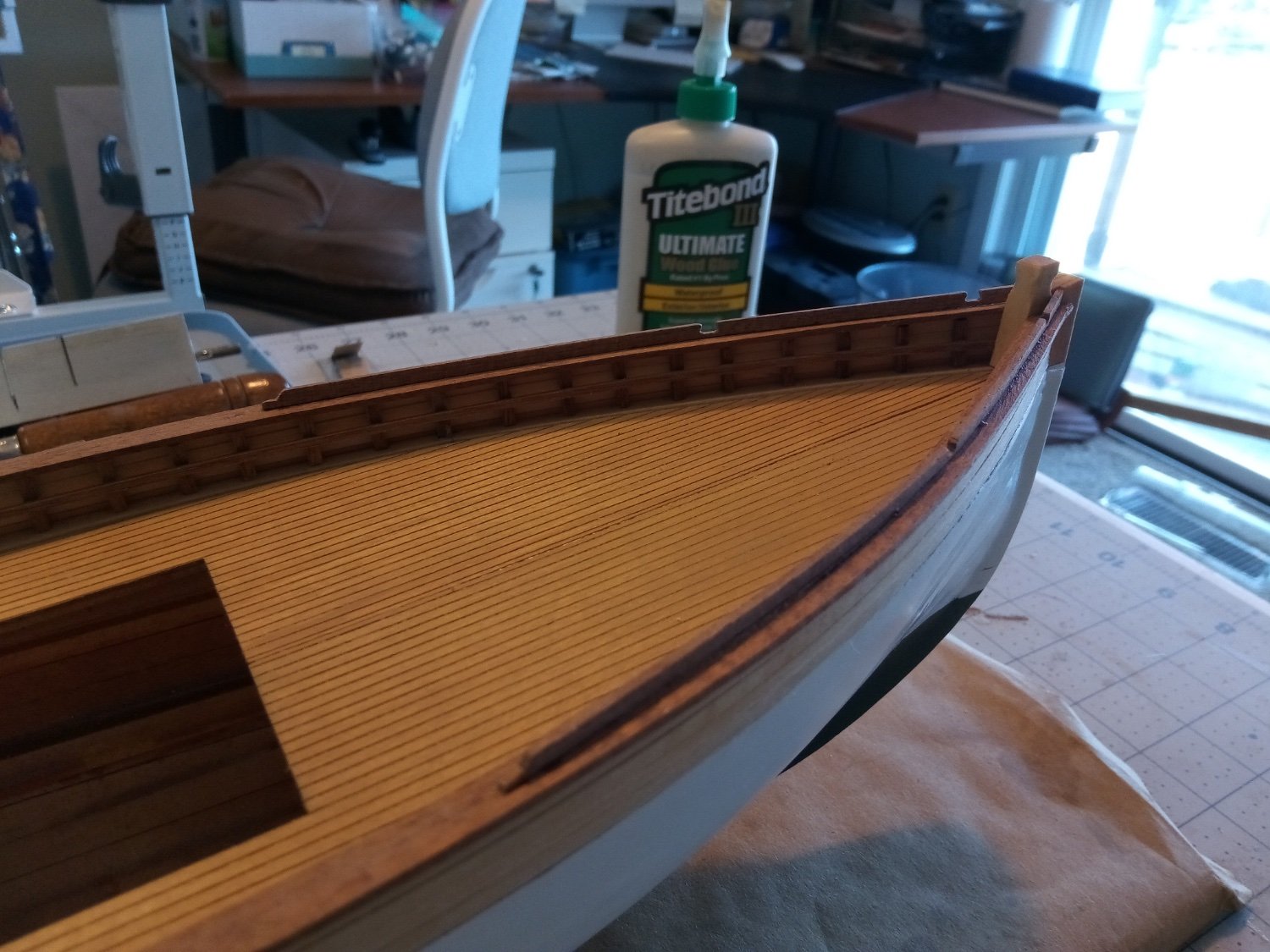
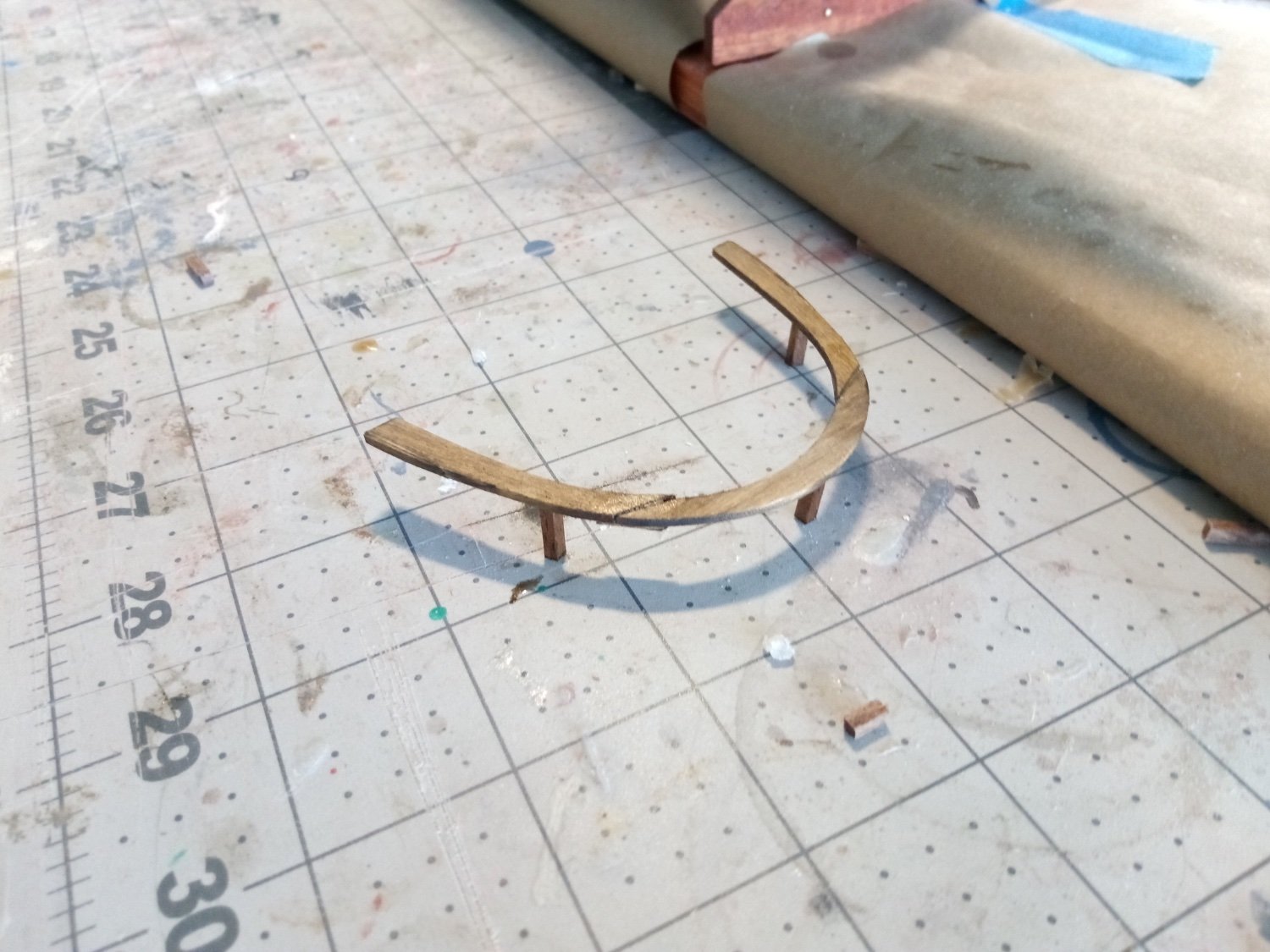
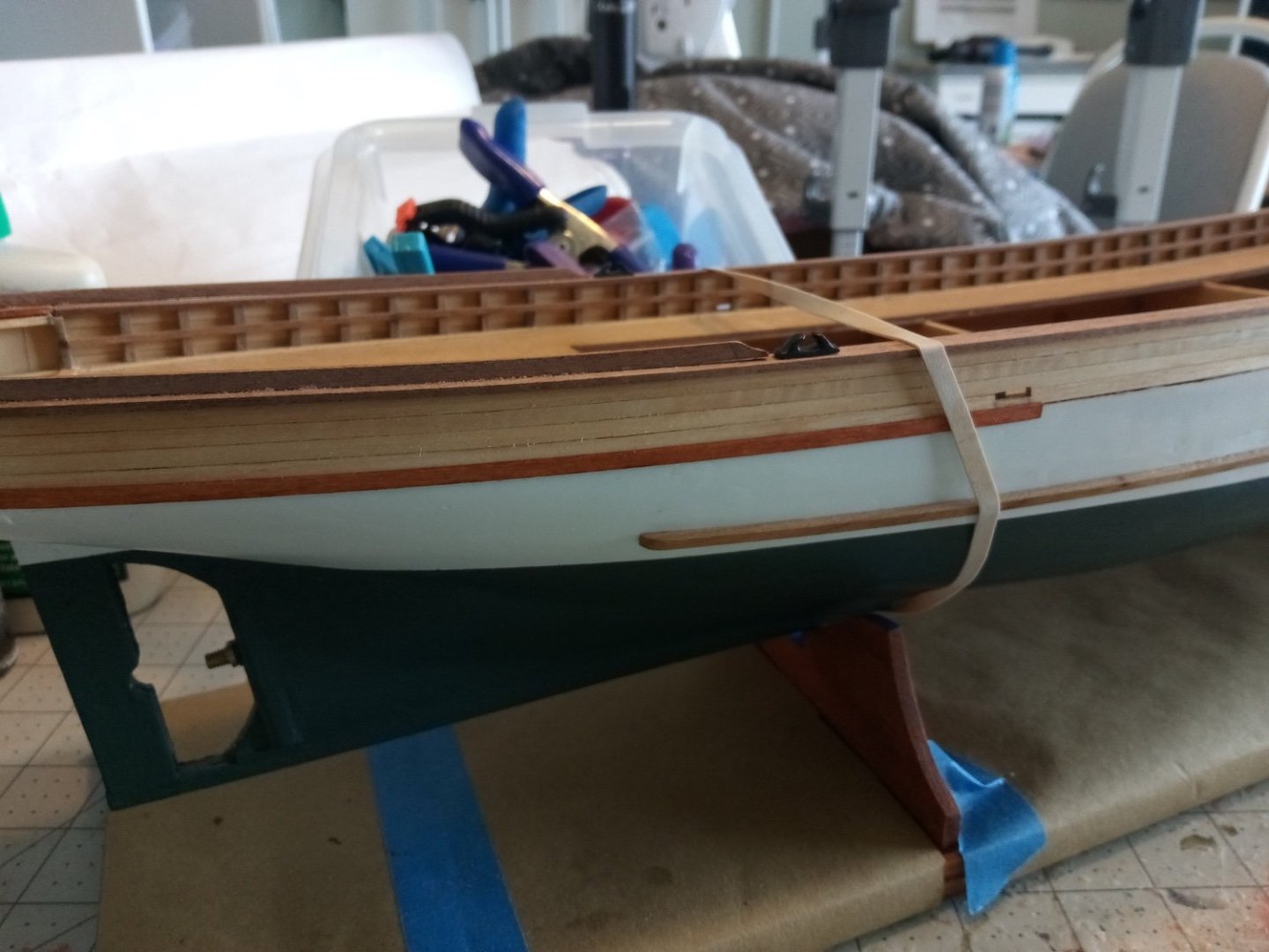
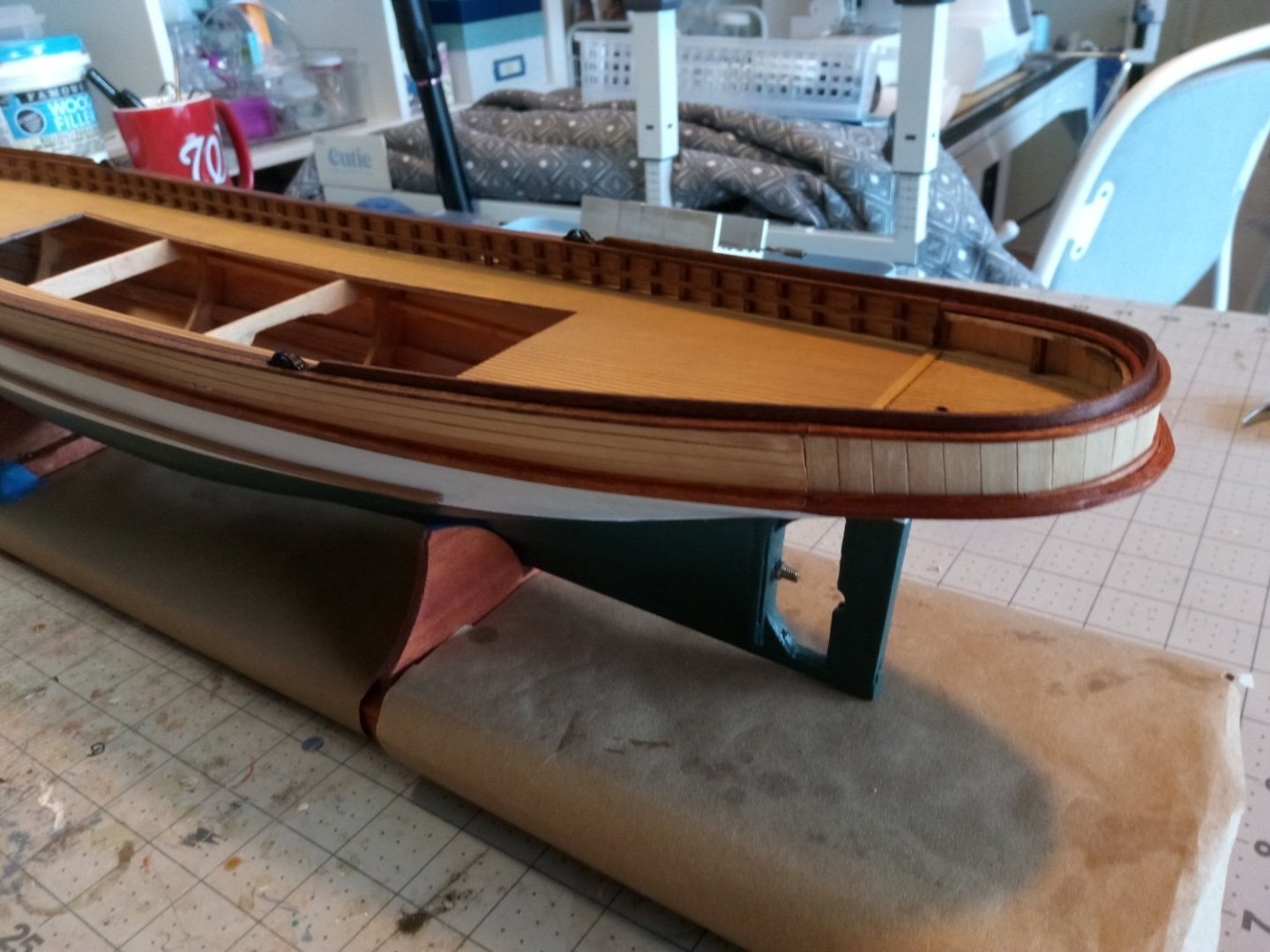
12. Caprails Before adding the caprails I decided to add the “cleats” which run inboard of the frame extensions and serve as a tie-off point for fenders and dock lines: The caprails are 1/4” wide. Since the curve around the fantail is fairly tight the kit recommends using 4 1/16” pieces of strip wood, edge-glued after bending. After 4 attempts to bend the 1/16” mahogany strips 3 of them cracked, despite using hot water, ammonia, steam and heat. I found some 1/16” square strips of basswood in my spares box and and after some experimentation with some exterior stain I had for a fence, I was able to get a good match with the color of the mahogany and was able to bend them: The cap rails forward of the fantail are made up of 2 1/8” mahogany strips, edge-glued and like the fantail pieces, mounted so that there is a 1/16” outboard overhang. Here the outboard piece has been added on the port side: The Buffalo Rail sits on top of the caprail around the fantail. It is 1/8 x 1/16 mahogany and unlike the smaller pieces I had no problem bending it after soaking: Near the bow the Log Rails sit on the caprails. The stem was shortened to be flush with the top of the log rails and the Forepost was made from 1/4” square stock and added aft of the stem. Next will be the rub rails


- 72 replies
-
- 10
-
-
- Seguin
- BlueJacket Shipcrafters
- (and 2 more)
-
I just found this. Very nice build. When I was stationed at Naval Amphibious Base Little Creek VA 1988-90 the Navy brought 2 ATFs out of mothballs and recommissioned them into our salvage squadron - I always like the look of them.
-
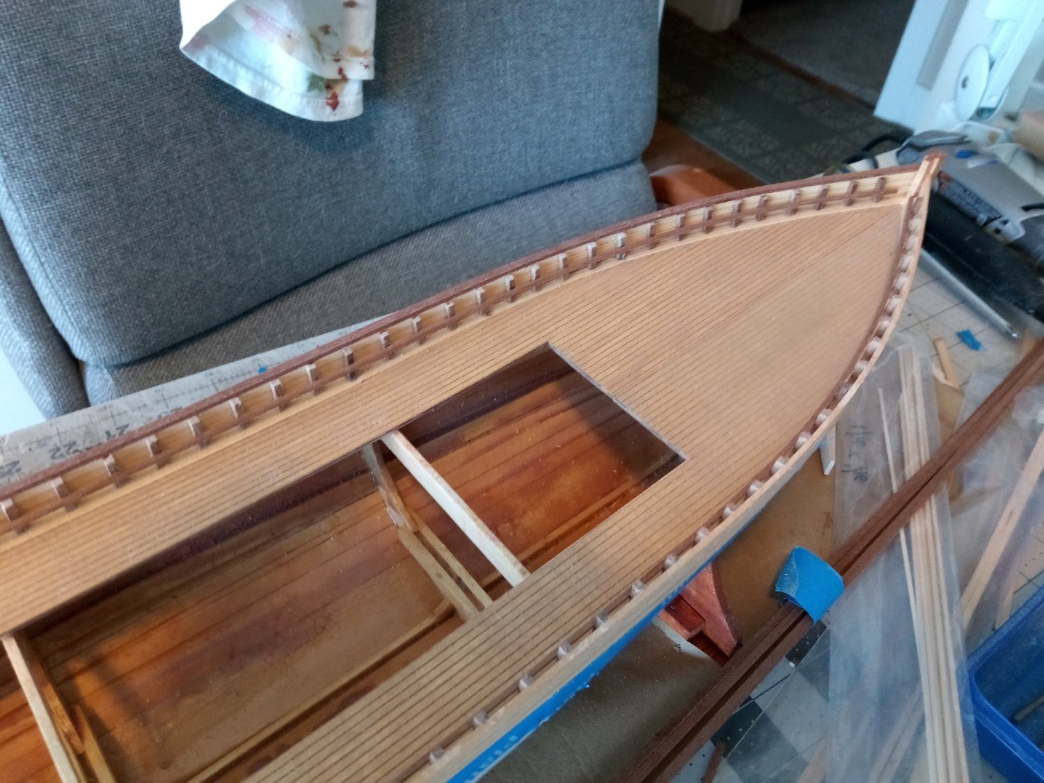
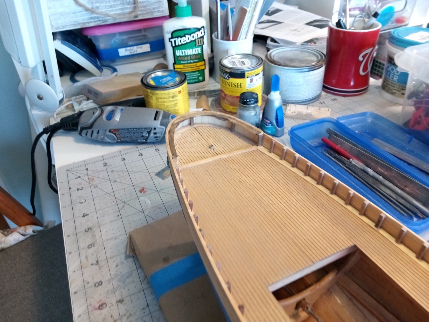
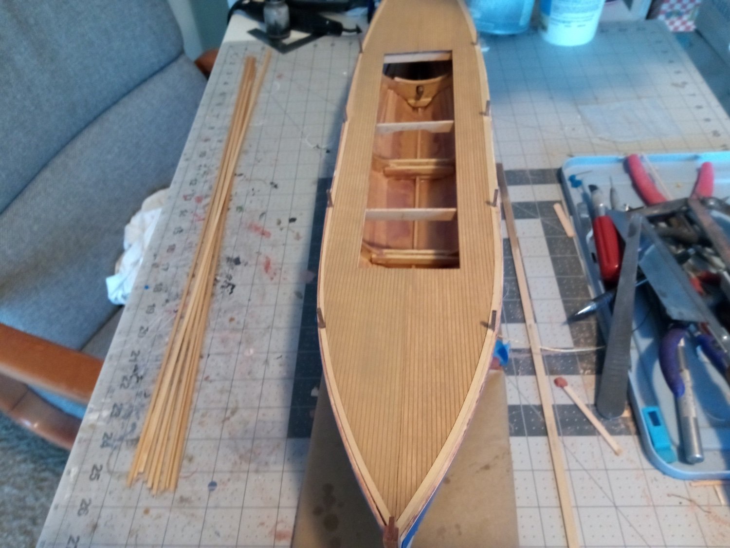
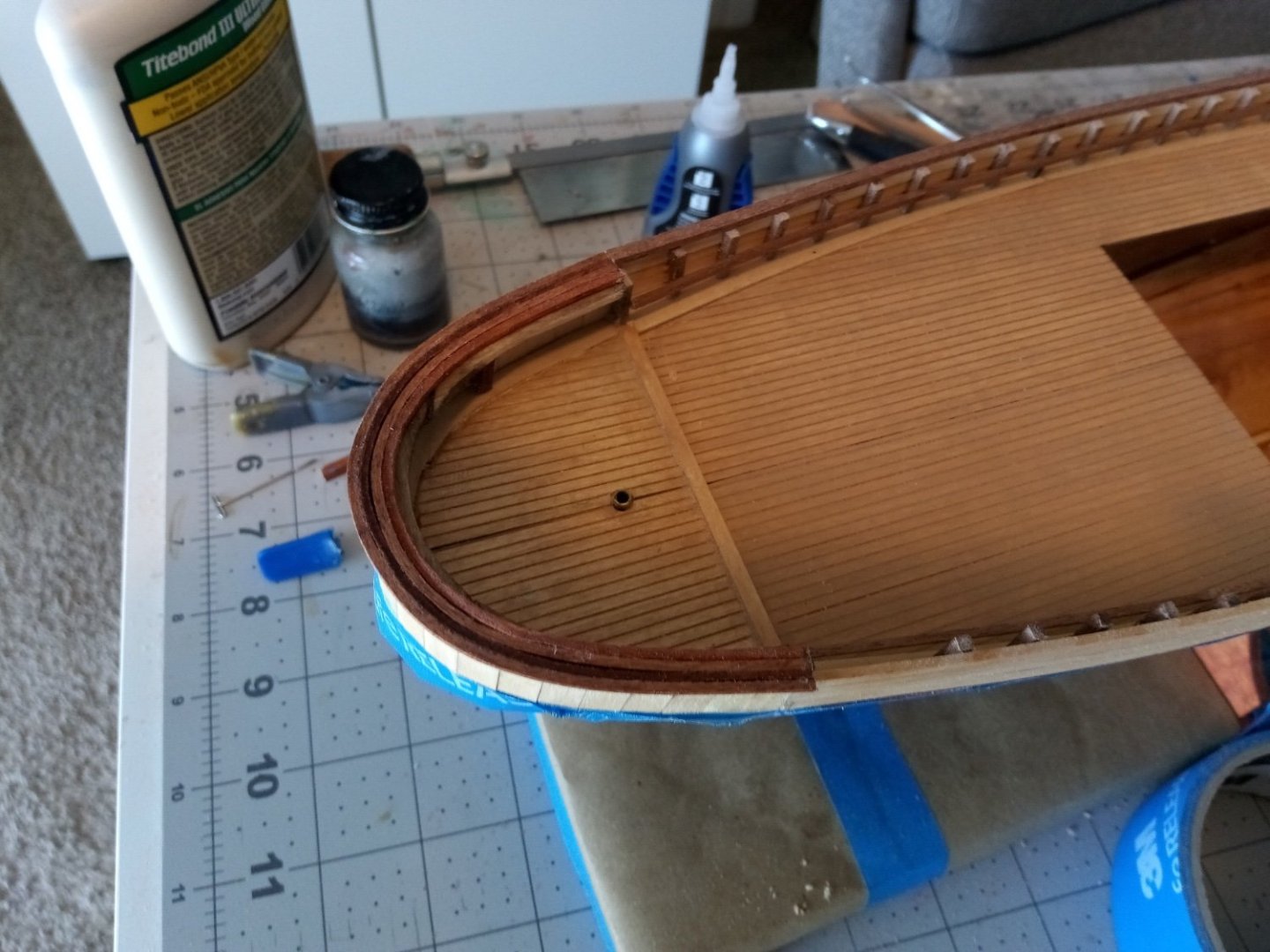
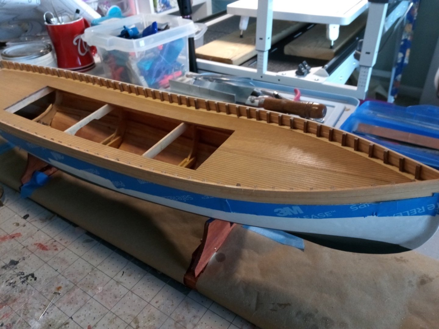
11. Bulwarks and Fantail The bulwarks went on pretty easily. After pre-staining them I edge glued the 1/8 x 1/16 strips, working about 3-4 inches at a time. After they were in place their aft ends were trimmed even with the aft edge of bulkhead #5 and the frame extensions were trimmed flush with the top of the bulwark planks. The “fake” frame extensions were added every 1/2”. The plans call for 80 of them but I needed 1 extra on each side between the stem and Frame#1 for a total of 82. They are 3/16” square mahogany. They were pre-stained, cut a little long, glued in place and when all were done their tops were sanded flush with the top of the bulwark planking. The fantail frame was fabricated from 3 laser cut pieces, identical to those provided for the waterways. They are glued together and then glued to 3 3/16” posts cut so that the top of the laser pieces will be flush with the top of the bulwarks. Once the fantail is in place it is just a matter of placing vertical 1/8 x 1/16 planks around it. If you are meticulous you could trim all the planks so that they fit perfectly. Since the aft-most strips will be covered by a name board I did not do that - I just alternated sides as I attached the planks so that the met at the aft centerline.


- 72 replies
-
- 9
-
-
-
- Seguin
- BlueJacket Shipcrafters
- (and 2 more)
-
Grant, I've seen some amazing work here on MSW, particularly over on the scratch builds, but this kit and your handling of it takes the cake. Amazing workmanship!
- 333 replies
-
- 10
-
-
Wonderful work!! Your non-painted wood looks better than painted!
-
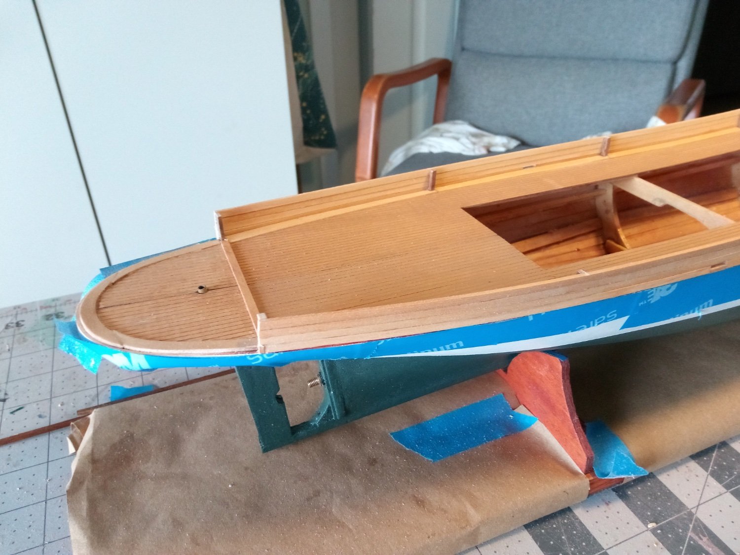
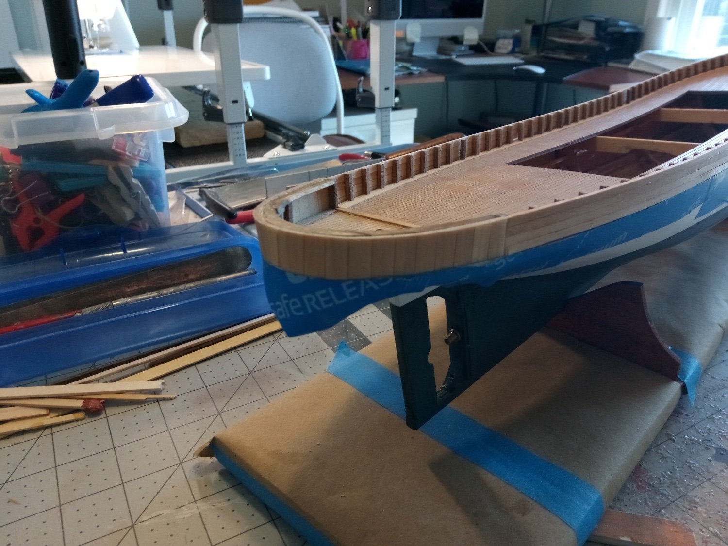
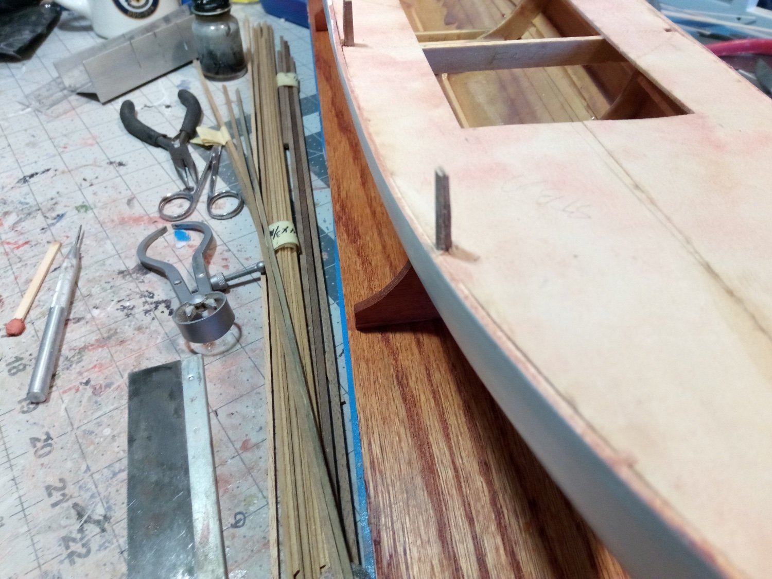
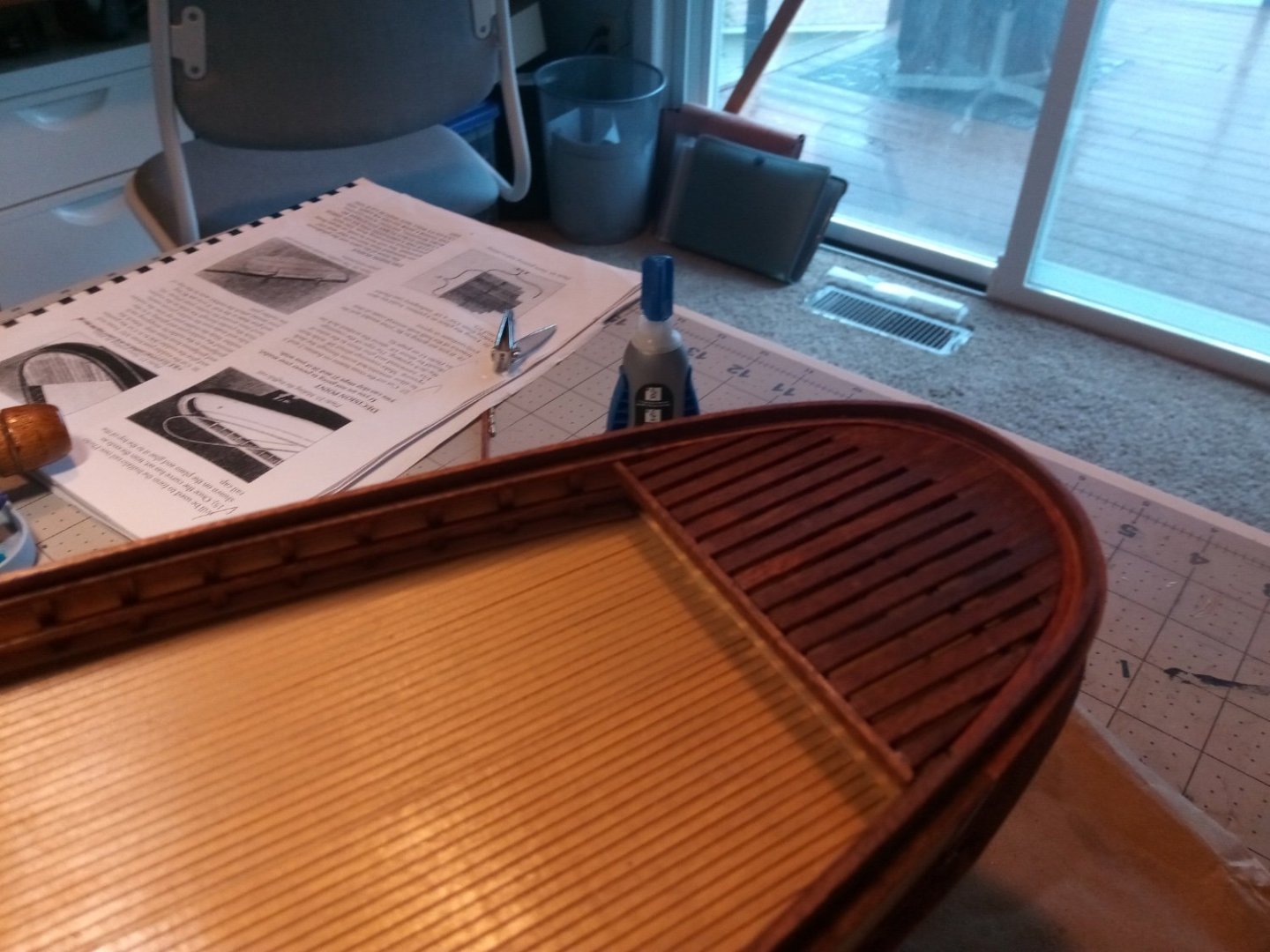
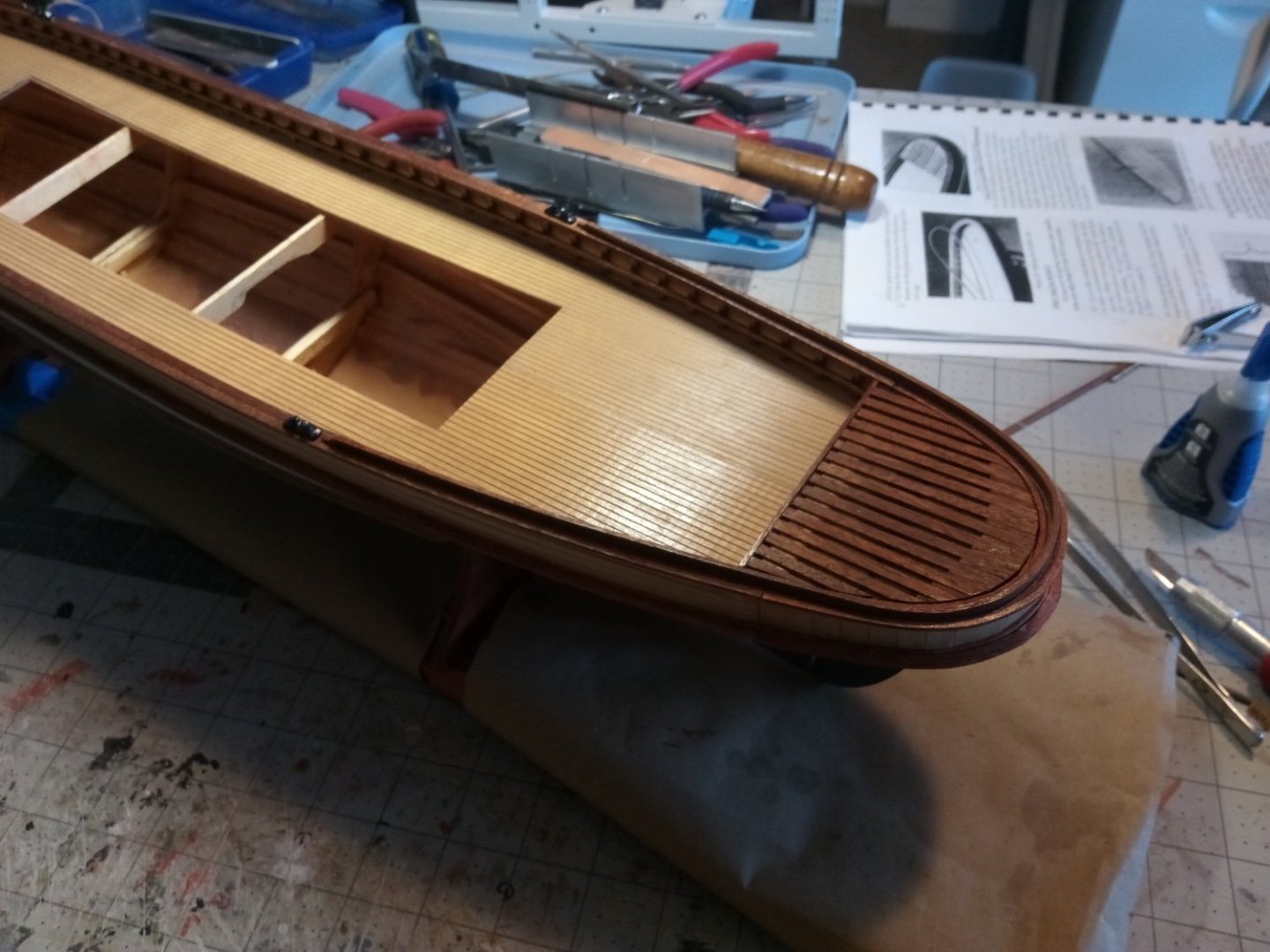
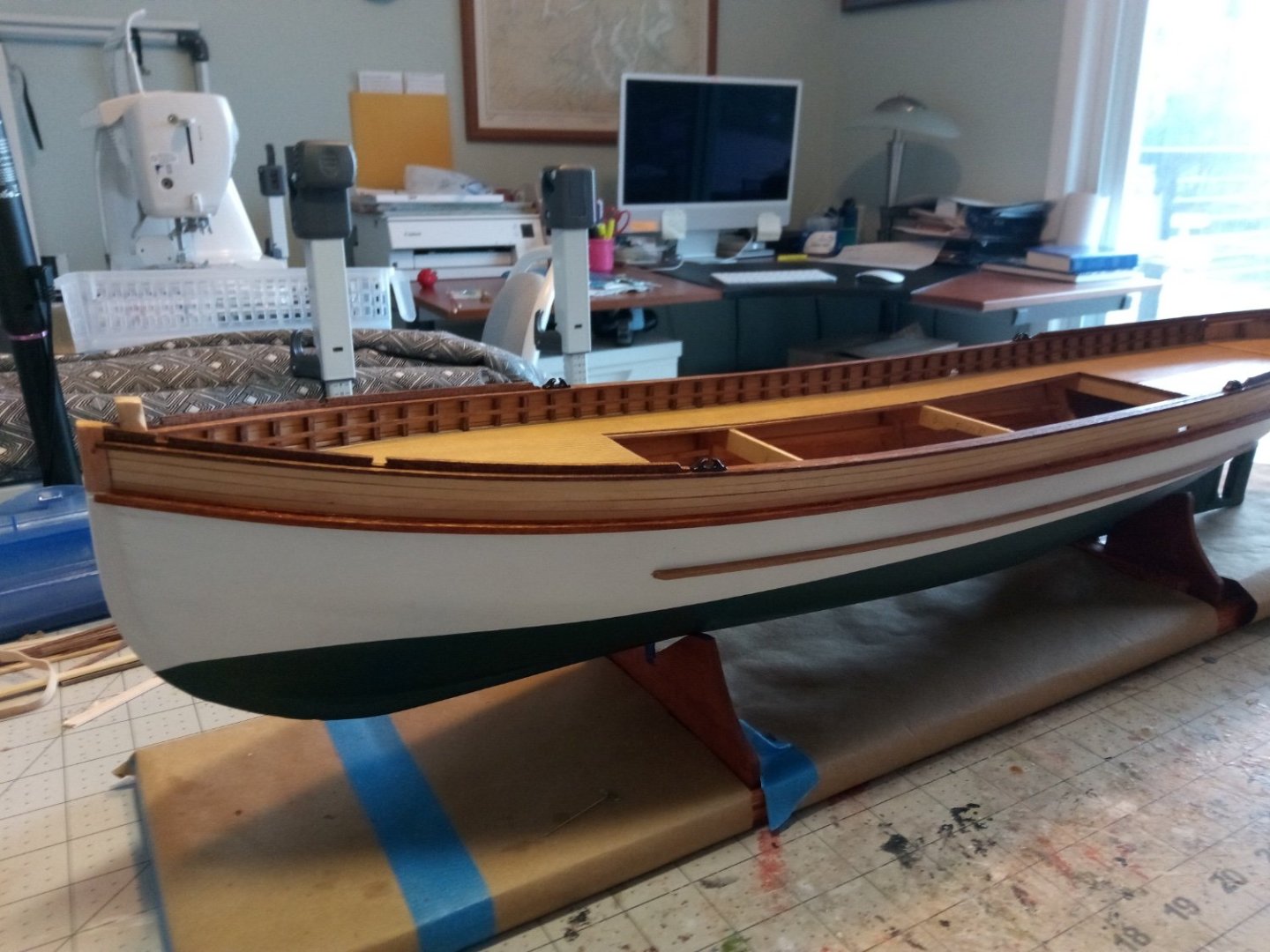
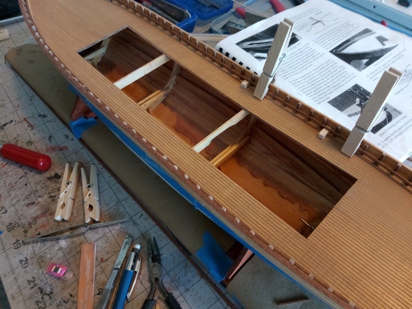
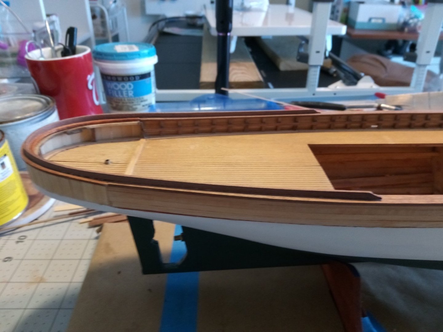
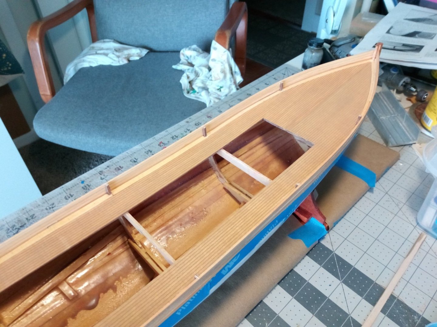
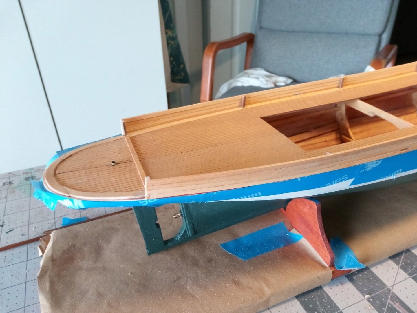
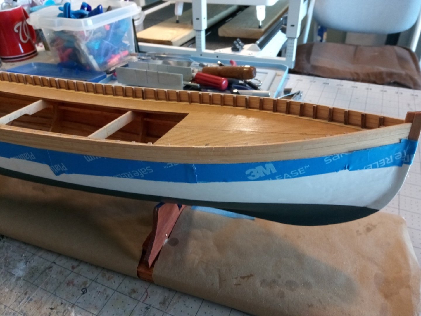
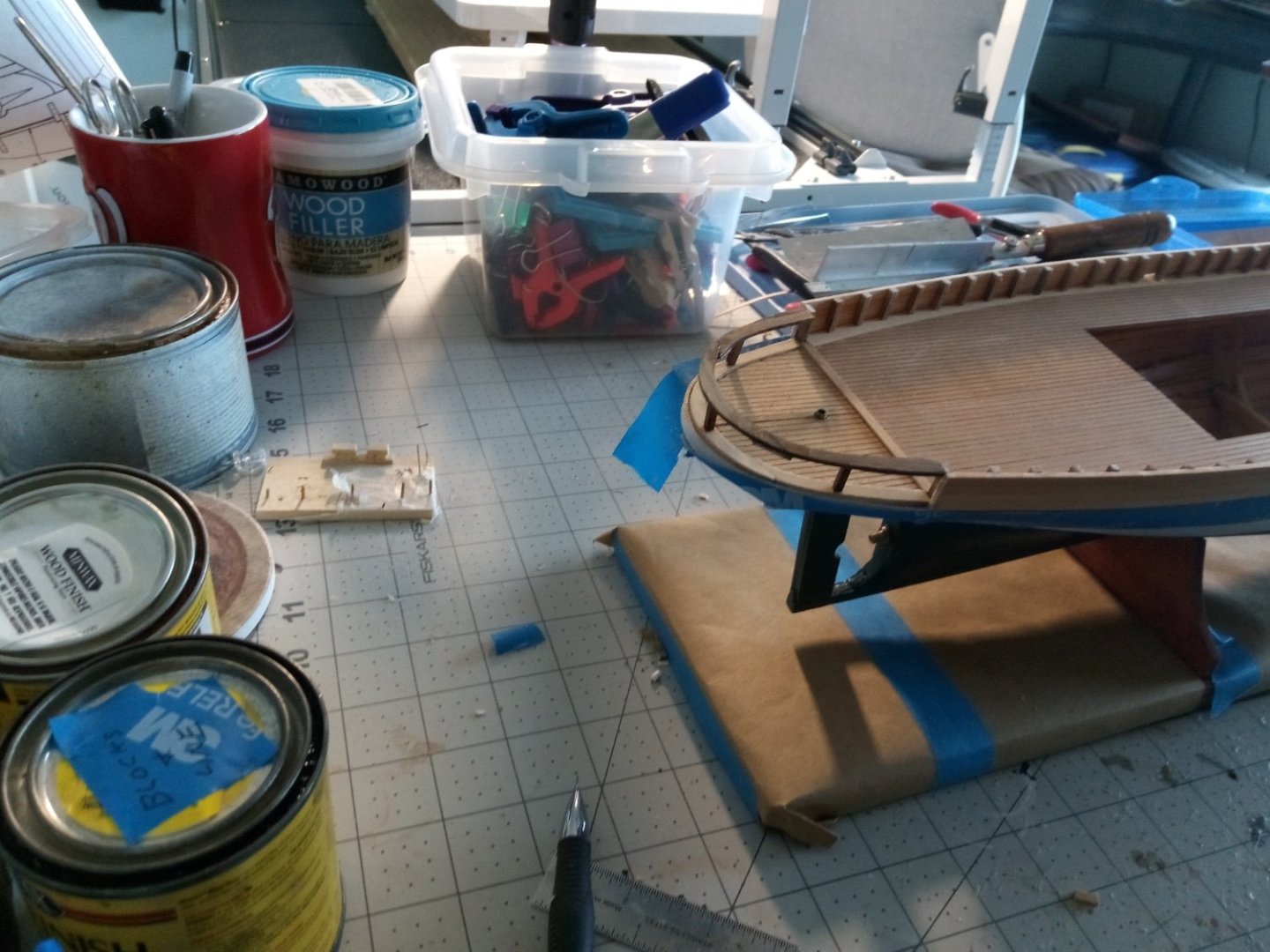
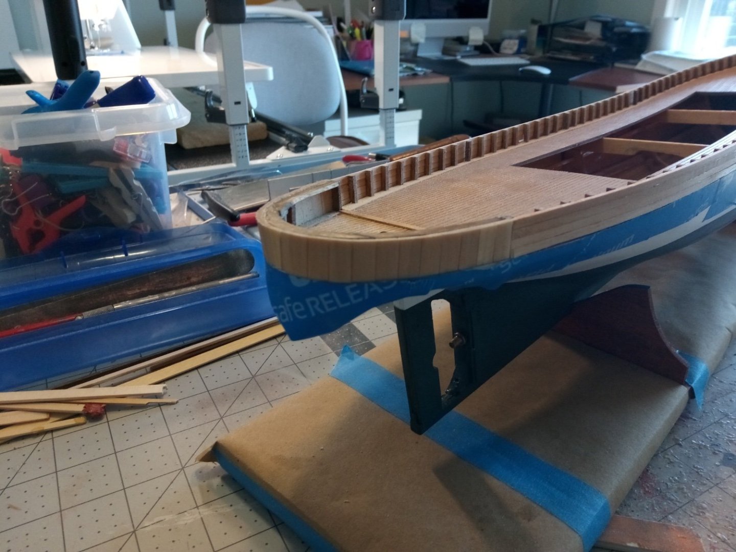
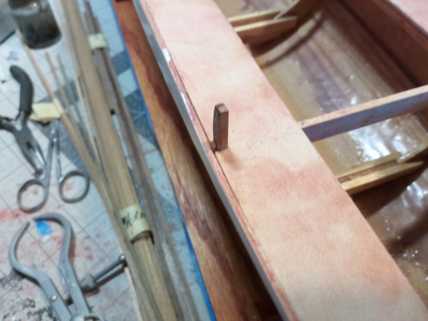
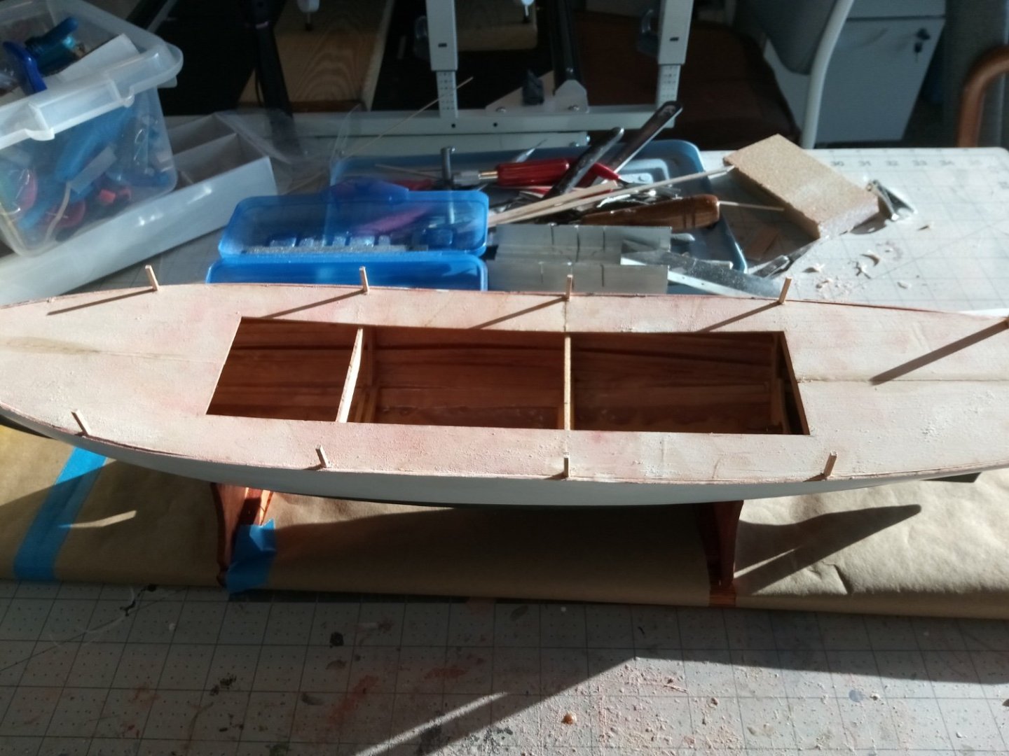
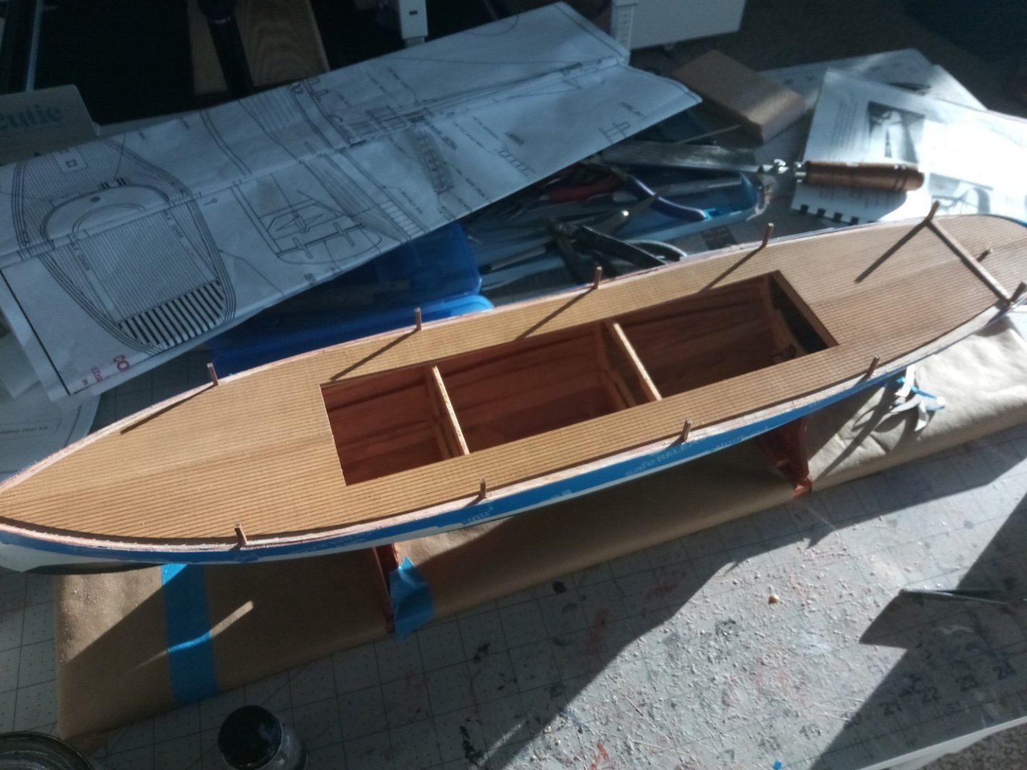
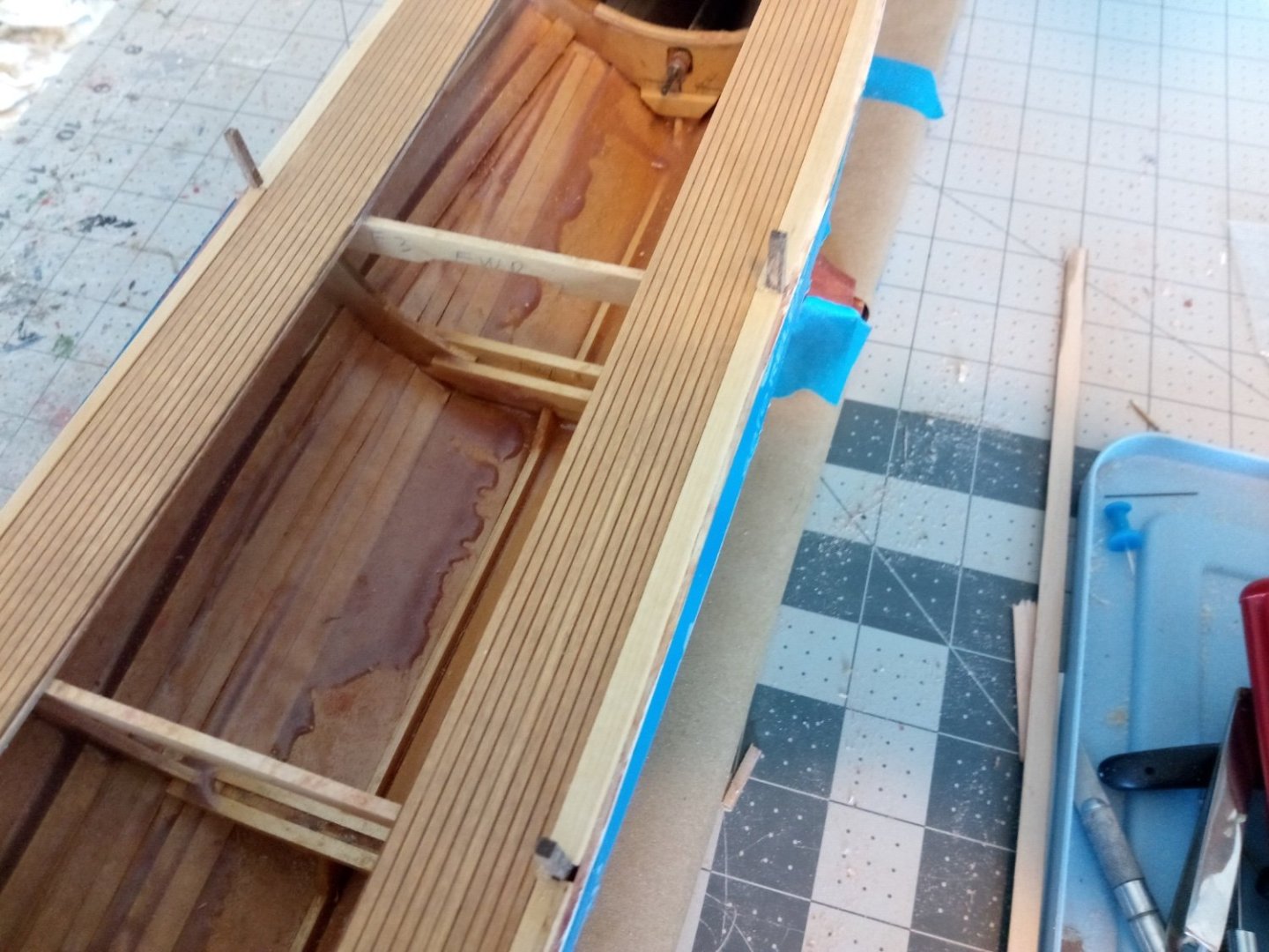
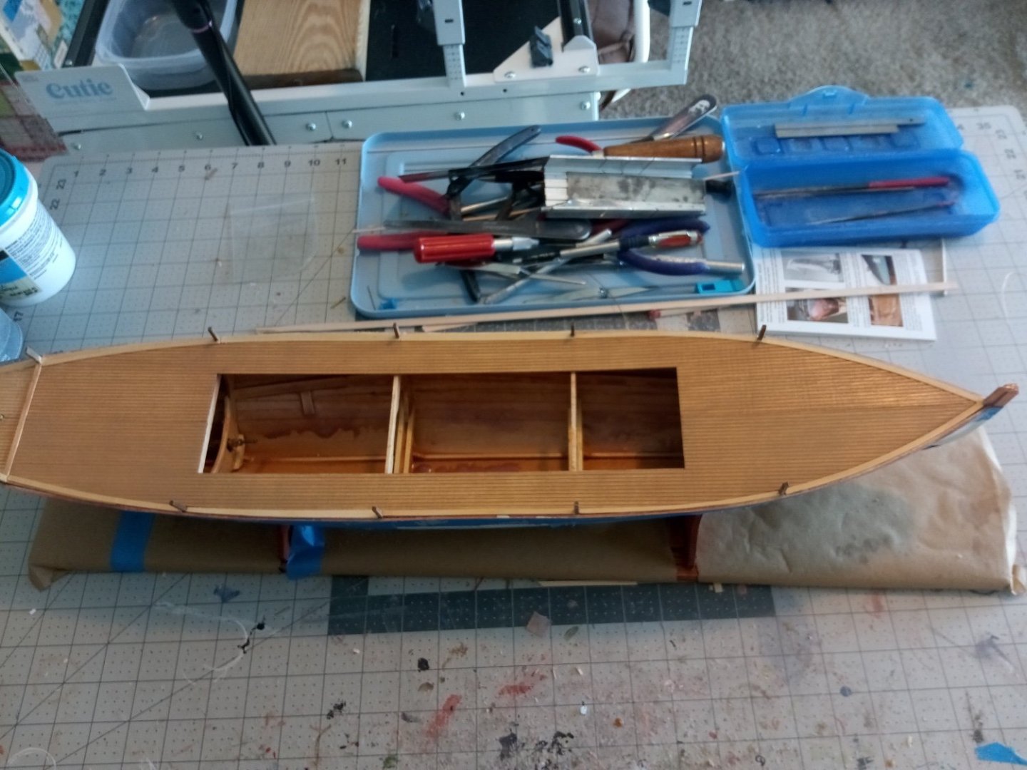
10. Laying the Deck and Waterways So far I have spent a lot effort during this build trying not to break off the bulkhead extensions that stick above the deck. As can been seen below, the extensions vary in dimensions and, most importantly, in the spacing between their outboard edges and the inboard edges of the top hull plank - they should be flush. After trimming and shimming I still did not like the results, I decided to cut them all off, except for the last pair on Bulkhead #5. These 8 extensions will be joined by 80-plus pieces of mahogany 3/32” square stock that will simulate the other frames after the bulwark planks are installed. In order to get these 8 properly placed, and looking just like their future neighbors, I replaced them with 3/32” Mahogany. They are pinned to the deck with brass rod for extra strength: Once that was taken care of I pre-stained the scribed decking with Old Masters Gel Stain (Fruitwood color). I’ve used it before for scribed decking and liked it. While not too impressive when it first goes on (looking like a light tan paint) it has the advantage of not blotching, which many stains can do on basswood, and then it darkens nicely over the next 24 hours and the deck seams really pop. The only recommendation I have for this step is be careful with the wood glue - I had a bad experience on another build where I used too much and the water in the glue caused the the decking to swell and buckle at the seams. This time I put a bead around the edges and then put a “chickenpox” scattering of dots around the interior. Although with some sanding of the joint between the 2 forward pieces I was able to get the seam to coincide with a plank seam and to get the seams to line up between the fore and aft pieces I could not get an invisible transverse seam between the main pieces and the 2 smaller ones that sit aft on the transom so I just covered it with strip wood - it will be pretty much out of sight under a grating. The waterways took a little longer than I thought they would. The instructions call for fitting 3 laser cut pieces around the transom and 1/8 x 1/16 strip wood between the frame extensions (there is a diagram in the instructions but the one on the plans make it much clearer). For the transom pieces I removed wood from the decking as need to get the laser cut pieces to fit flush with the inner edge of the hull planking - I did not alter the laser pieces because they need to match an identical set that will sit above them, forming the frame for the vertical transom planking. For the waterways forward of the transom I took a different approach and left the edges of the scribed decking alone since any variations to its smooth run would be really obvious. So instead I trimmed the waterways where needed to get them to fit and added to their outboard edges if necessary to avoid a gap between the waterway and the bulwark planking. Each piece of waterway was a little different. Next up will be fitting the bulwarks.


- 72 replies
-
- 8
-
-
- Seguin
- BlueJacket Shipcrafters
- (and 2 more)