schooner
-
Posts
741 -
Joined
-
Last visited
Content Type
Profiles
Forums
Gallery
Events
Everything posted by schooner
-
 Thanks! Compliments coming from someone with your skill means a lot. Not just modeling skill either - your photos are top notch. Not sure what my problem is but when I looked at the last photo above I though "how could I get that chestree so crooked?" But when I went to fix it it is on nice and straight and parallel to the gun port. Strange. Maybe it's related to the Coriolis effect.
- 142 replies
-
- 1
-

-
- alfred
- solid hull
- (and 2 more)
-
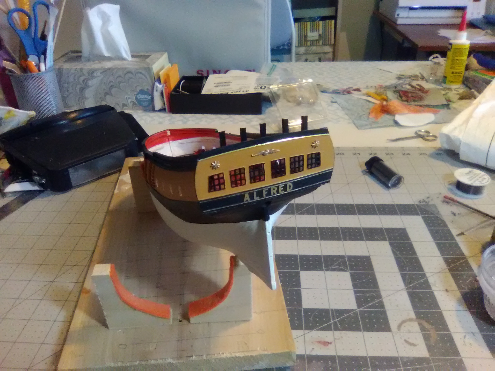
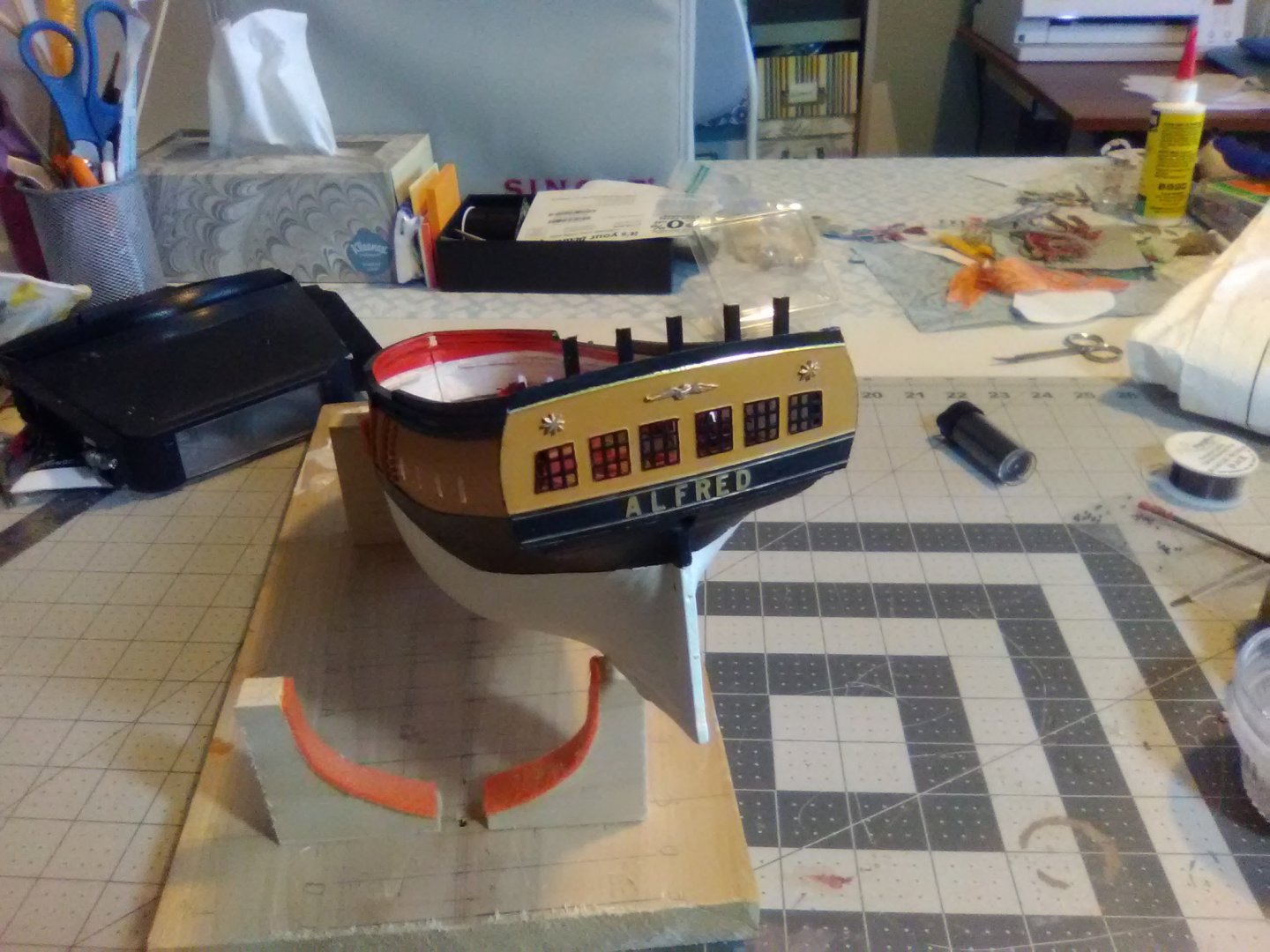
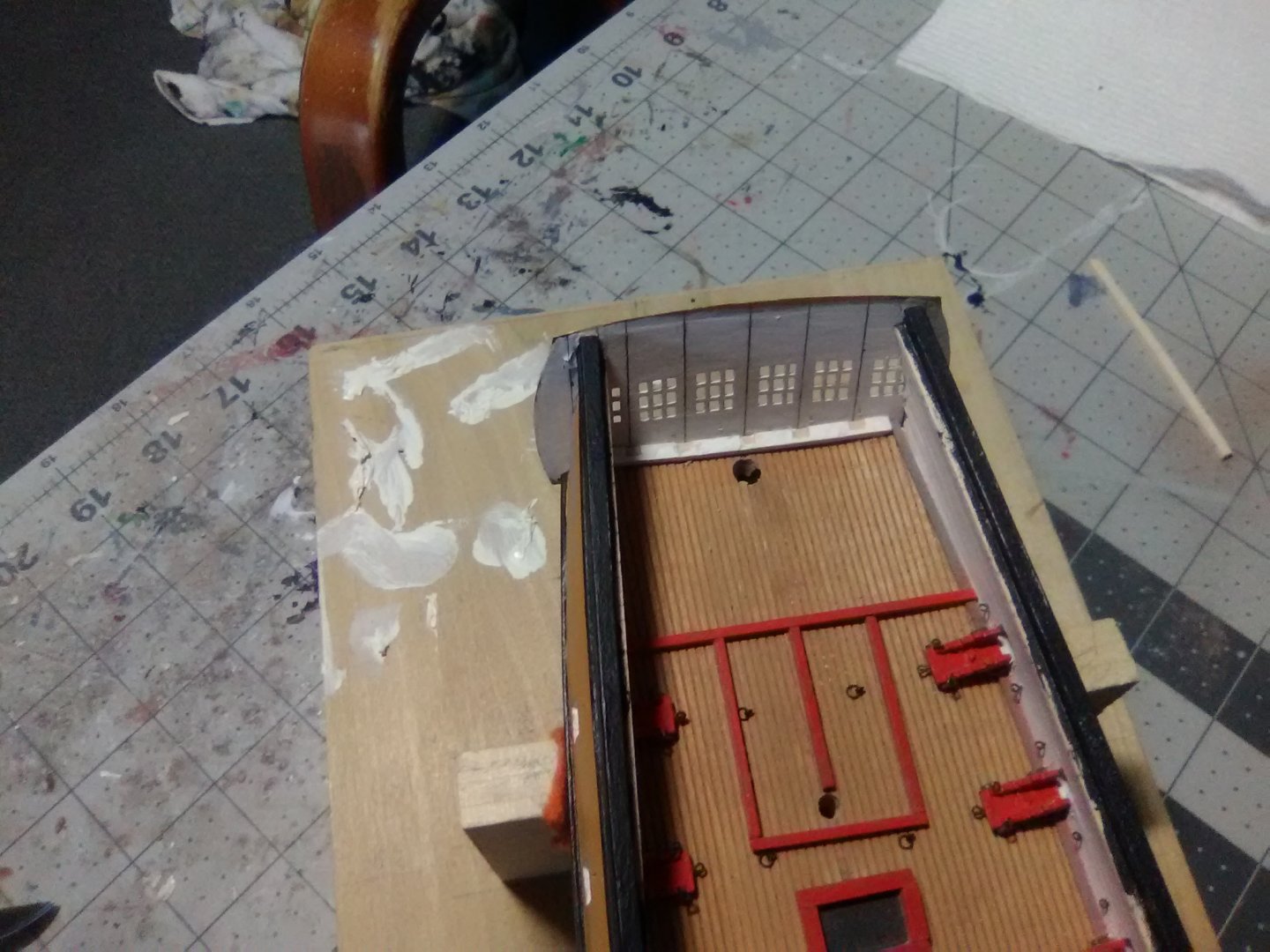
Transom finished The final details on the transom are in place including the wings and the adjacent fashion pieces, the trim on top of the counter and the britannia eagle and stars. The top edge still needs thickening but I can’t do that until the deck planking is in place. Other exterior details include the sea steps per the plans. The fenders and chestrees are not on the plans but I’ve seen them on just about every model of contemporary ships so I added them.

- 142 replies
-
- 7
-
-
- alfred
- solid hull
- (and 2 more)
-
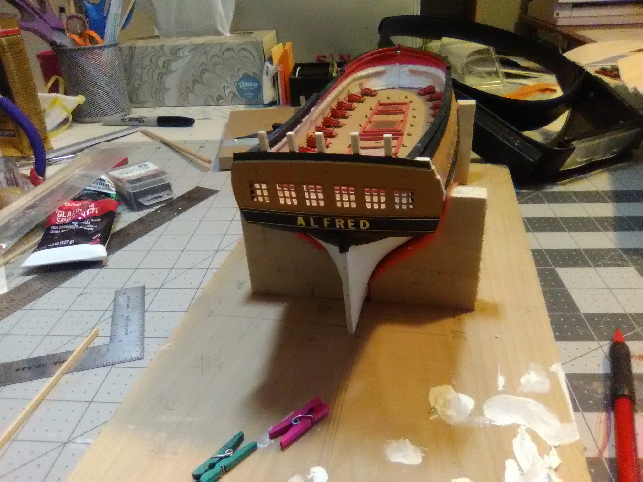
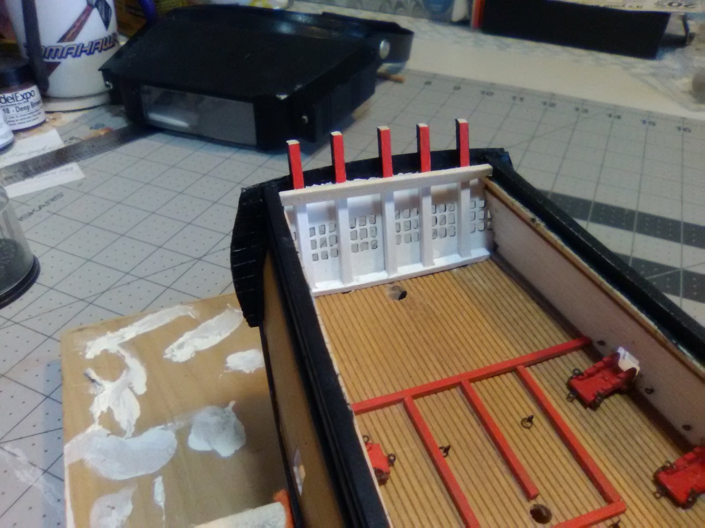
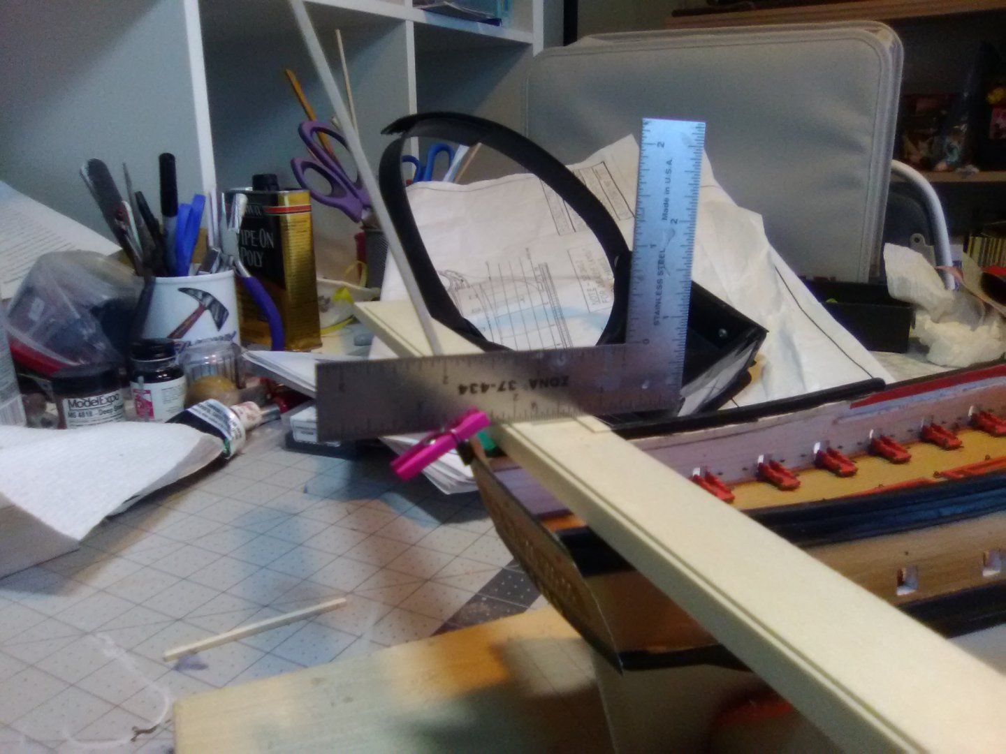
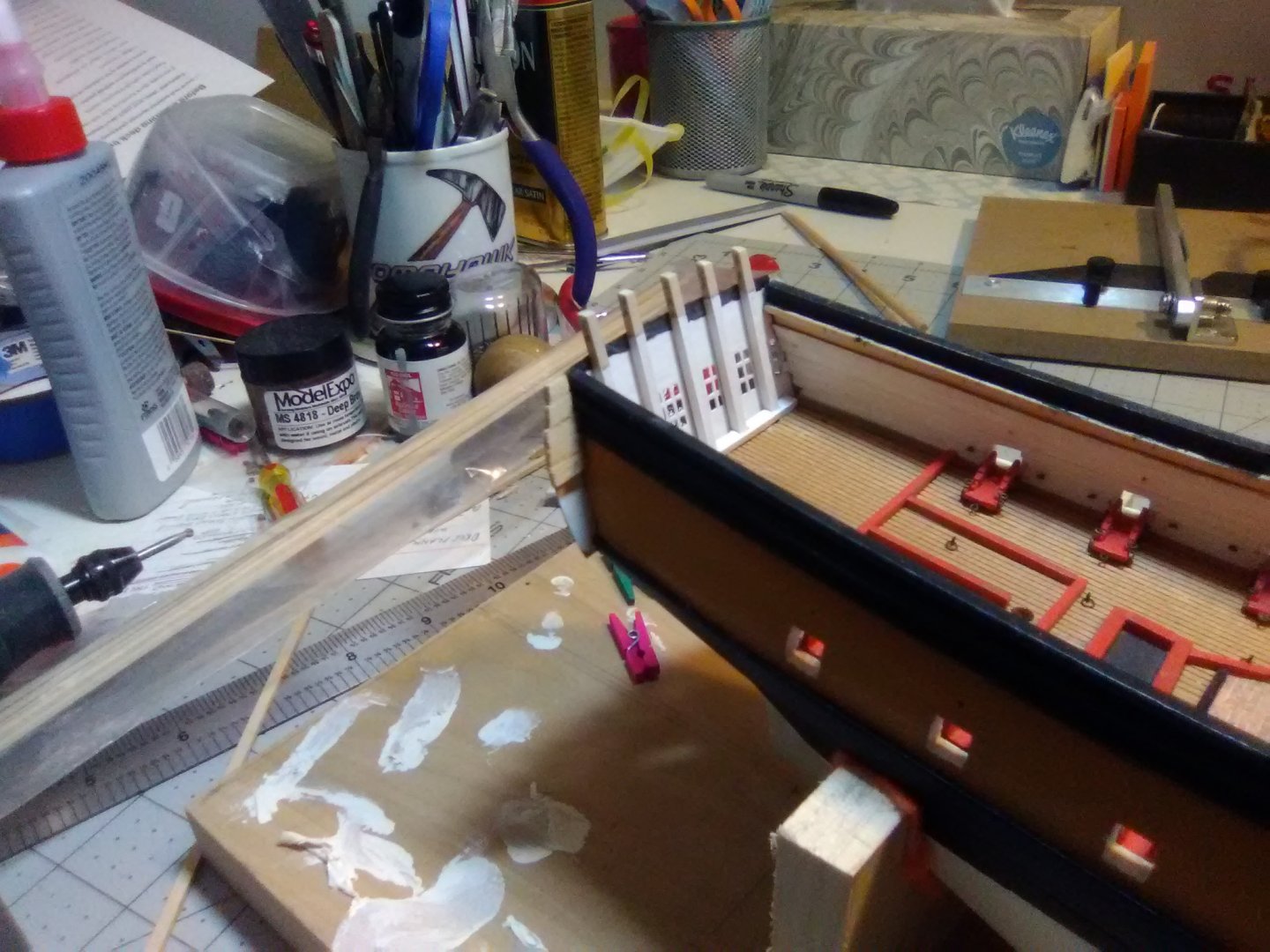
Transom (cont.) Well my mortice work did not work out, when I glued the PE in place the mortices did not line up with where the posts needed to go - I figured out that the windows are not centered on the PE, they are not off by much but enough that I had to re-do the mortices so I put them on a piece of strip wood and secured that to the deck. The next problem was how to figure out how long to cut the posts and to make the tops a level despite the aftward slant of the posts. According to the plans the railings on the sides of the quarterdeck are 9/32” high, since the taffrail posts have to join them they needed the same vertical height - which does not equal length, since they are not vertical. I placed some strip wood across the bulwarks that stacked up to 9/32” and used a ruler to mark where to cut the taffrail posts before installing them: After getting the first one cut and dry fitting it I could tell something was not right - it looked too short. It is too short - 9/32” is equal to just over 2 ft high at this scale which is too low for a railing - it would not keep anyone from going over the side it would just ensure that they went over head first. After looking at the plans I found the problem - the outboard profile shows the railing height as 9/32” (2 ft scale) but the hull section and inboard profiles both show them as 3/8” (3 scale ft) which is much more realistic so I modified my marking jig and cut the timbers for 3/8” height. The next step is to thicken the “wings” where the transom extends outboard of the bulwarks - a typical feature on merchant ships of the period, which Alfred was before her conversion. You can see the same wings on models of the Fair American and Rattlesnake. PE is great stuff but if it can be viewed edge-on it always looks under scale due to it’s thinness. I’m in the process of “planking” the wings with 1/16” strip wood which matches the plans and scales out at 6” thick. Fancy piecework will cover their inboard ends.

- 142 replies
-
- 6
-
-
- alfred
- solid hull
- (and 2 more)
-
The PE has been a real boon for me - I can never get windows to come out square.
- 142 replies
-
- 2
-
-
- alfred
- solid hull
- (and 2 more)
-
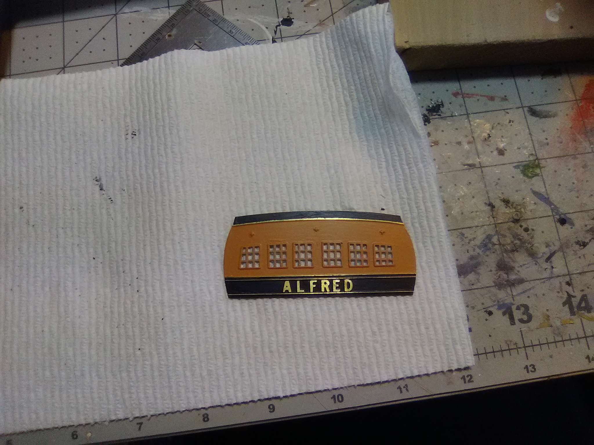
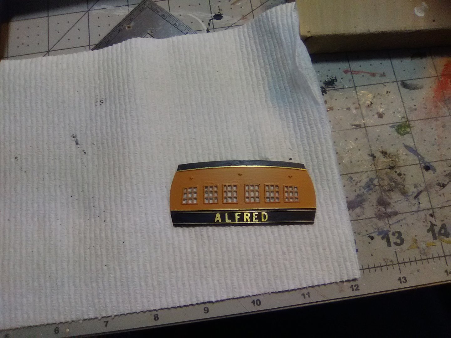
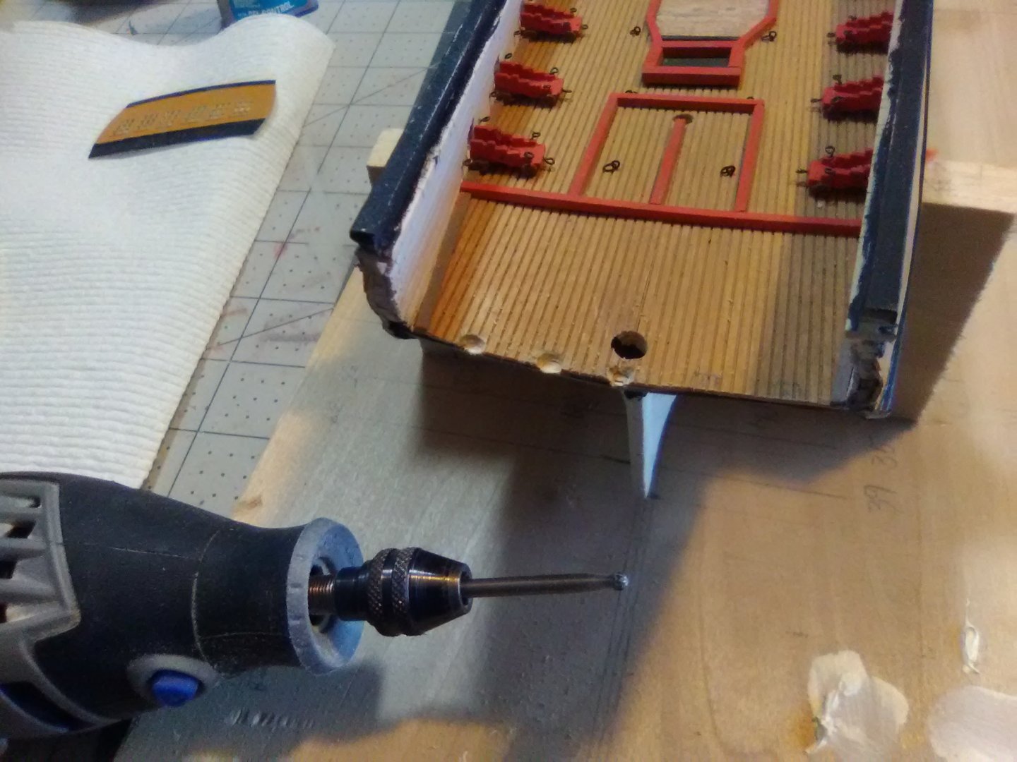
Transom preps The kit provides a nice piece of PE for the transom. It’s easy to bring out the gilt trim and lettering by just painting over them with the background color and then sanding off the raised area. The 3 small crosses above the windows are the mounting locations for a britannia eagle and some stars that will be added later. As far as installing the transom I’m deviating quite a bit from the directions both in regard to timing and technique. The instructions call for installing the transom after the quarterdeck planking is installed and that just does not make any sense to me - I have no idea how you cut cut the planking to length without the transom already in place so I’m going to do it now. Also instead of installing the 5 transom/taffrail timbers first and then the transom itself ‘m going to reverse those step since the PE is flexible enough that I can impart the needed curvature to the transom once it is emplace (I hope!). I used a Dremel sanding drum to bring the aft ends of the the bulwarks to the correct shape and will have a good attachment surface for the PE. Prior to adding the transom I used a cutting attachment on the Dremel to open up the mortice points for the bottom of the transom timbers.
- 142 replies
-
- 6
-
-
- alfred
- solid hull
- (and 2 more)
-
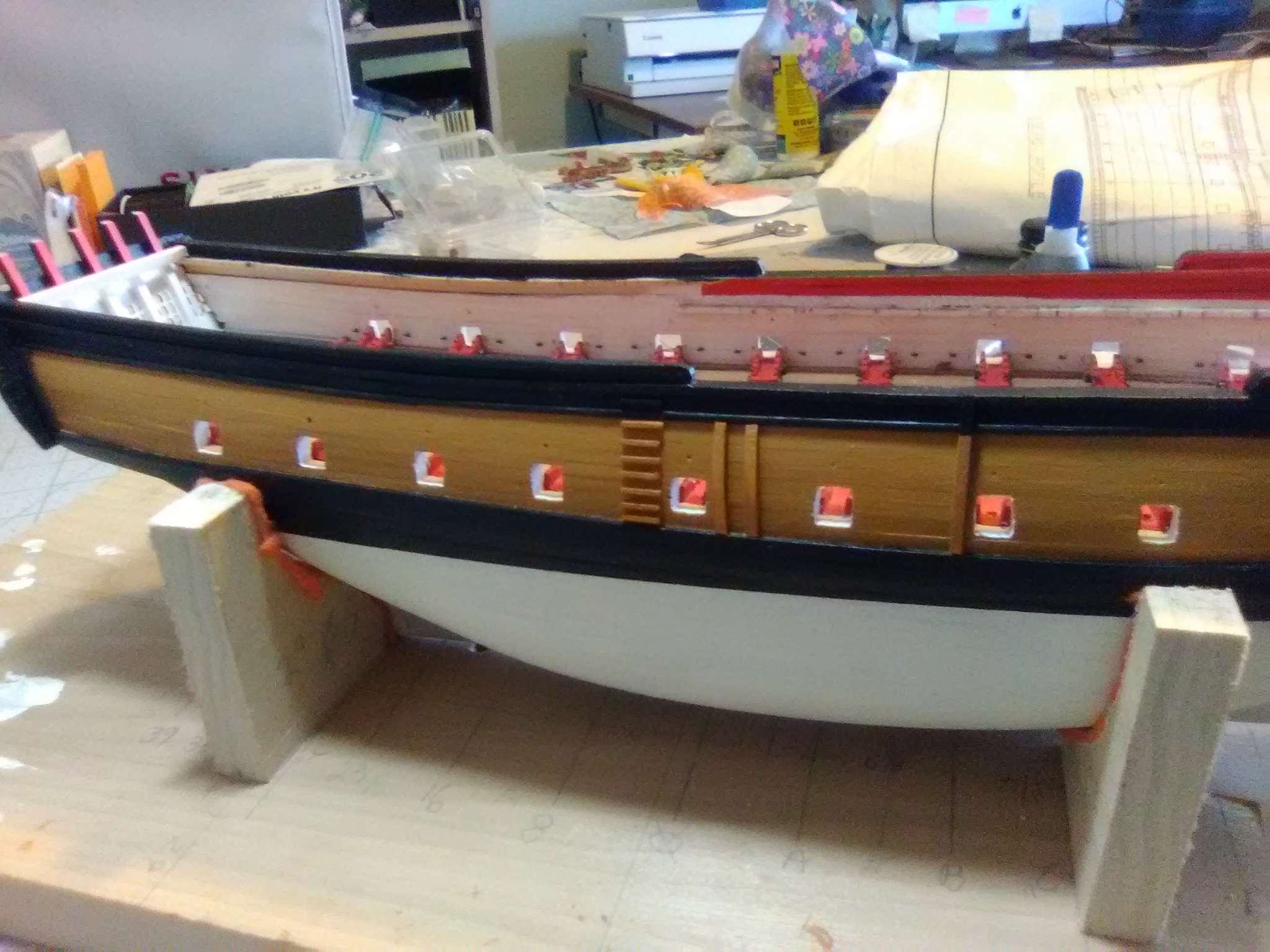
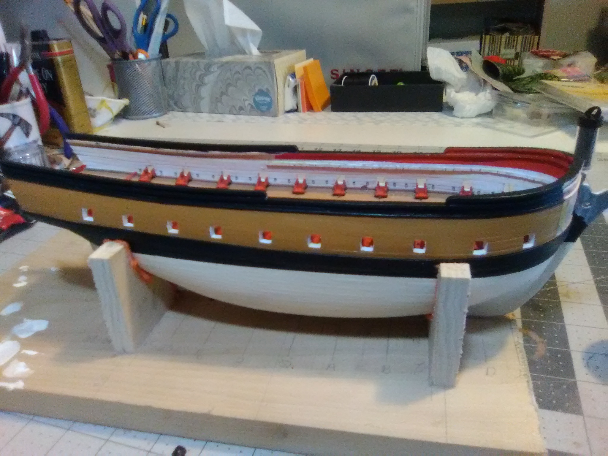
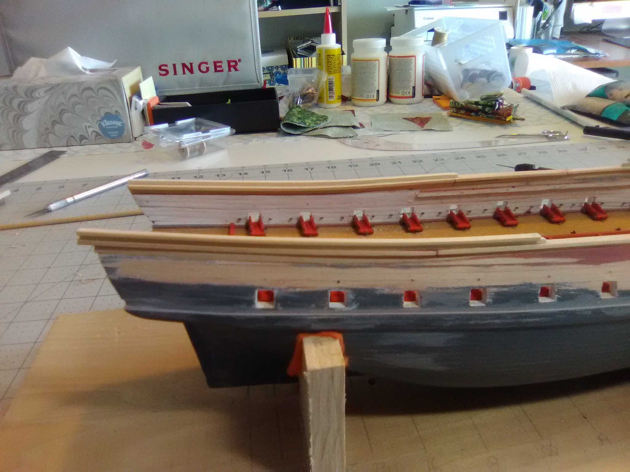
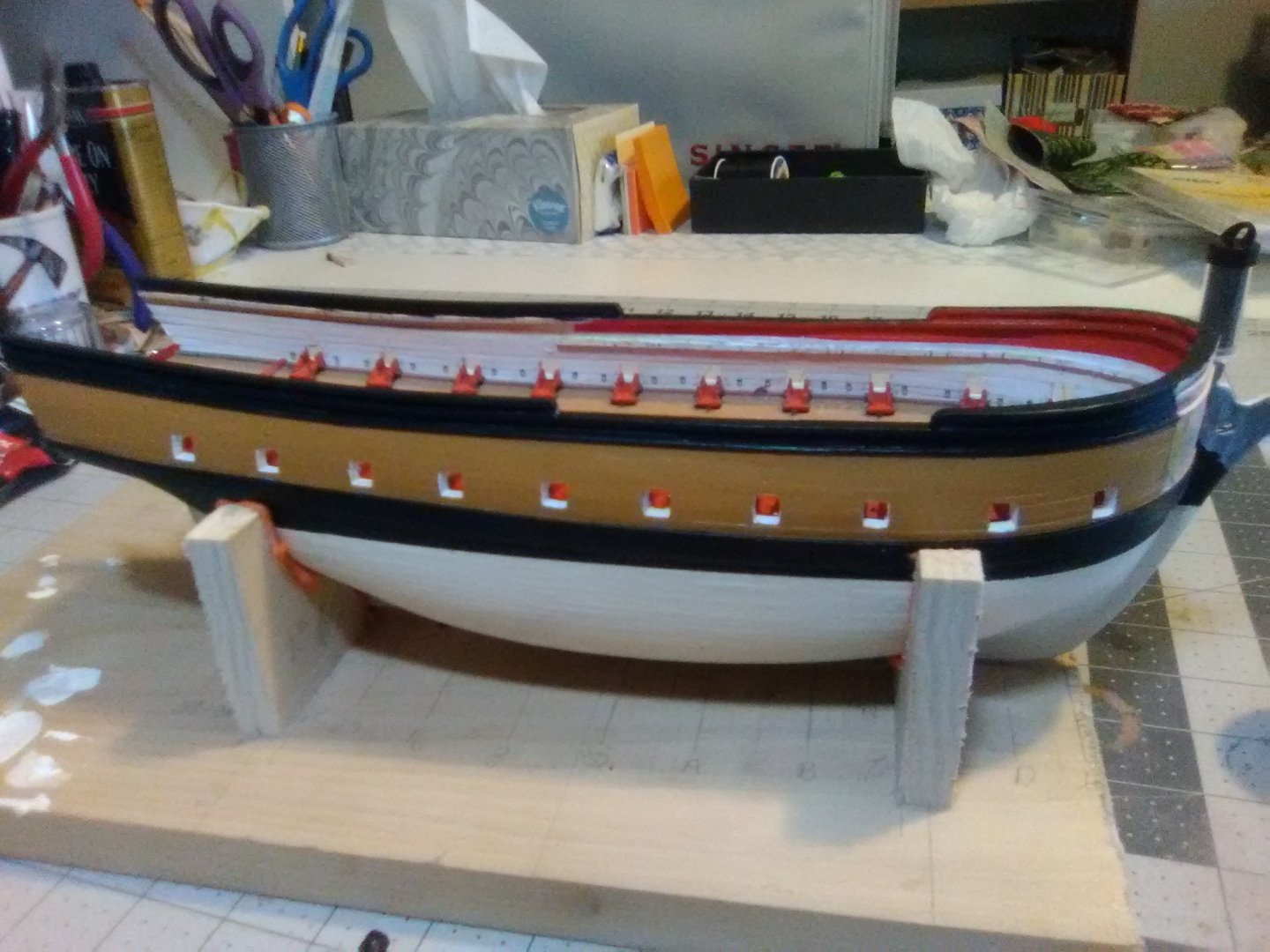
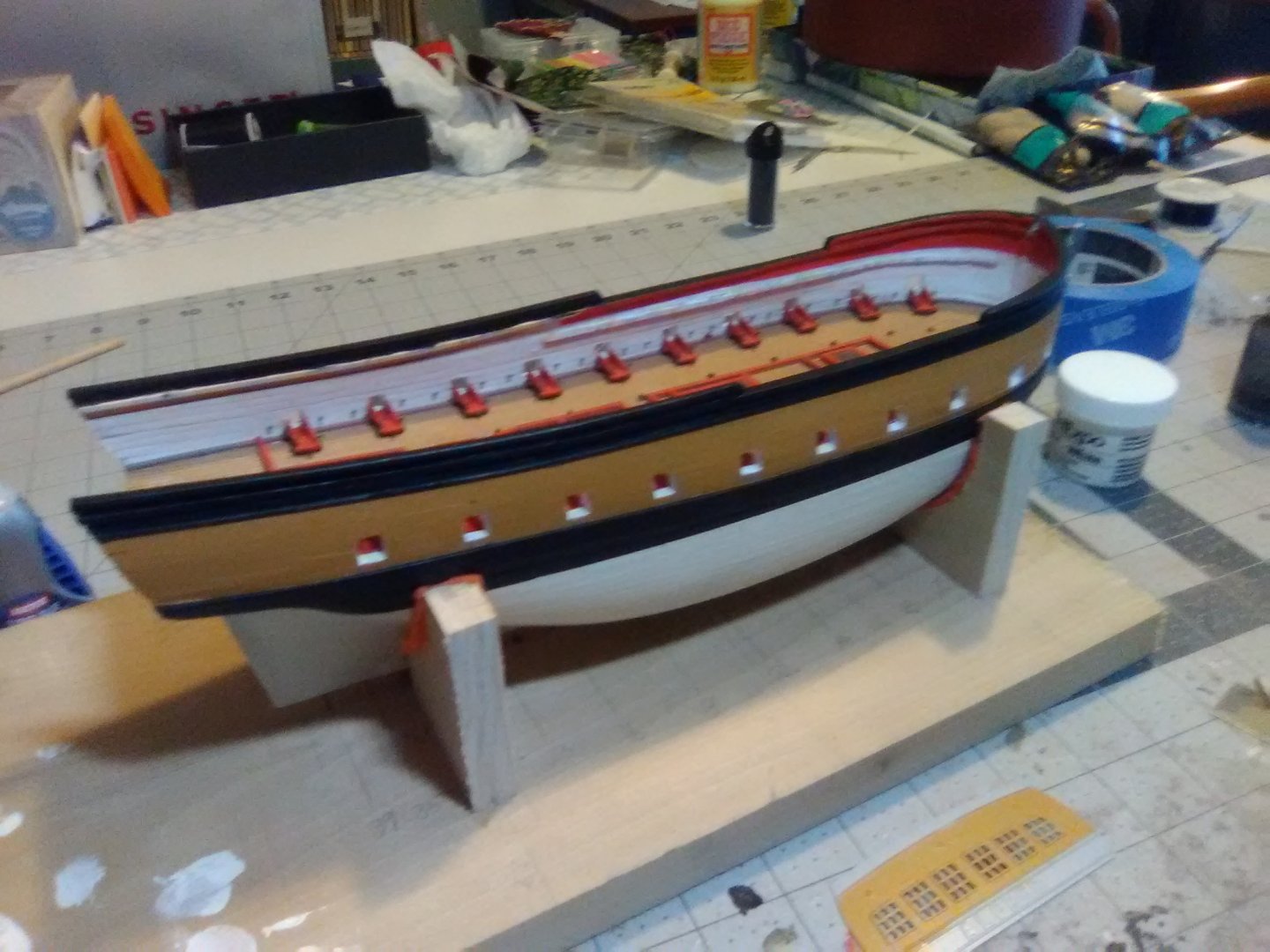
Painting the hull After a lot of taping, painting and repainting the exterior of the hull is done except for the area around the bow where the instructions recommend leaving it bare wood to help the headrails and cheeks adhere better when it comes time to put those on. Next I’ll be moving on to the transom.
- 142 replies
-
- 6
-
-
- alfred
- solid hull
- (and 2 more)
-
Rob, Thanks for taking the time to take so many close-up and clear photos of your rigging work and adding explanations - it will be a tremendous help to me when I get to that point on my little frigate. Your ratlines look really good! Did you tie them off on each shroud with a clove hitch?
-
They are not glued in - that would have been a major palm-to-the -forehead move!
- 142 replies
-
- 1
-
-
- alfred
- solid hull
- (and 2 more)
-
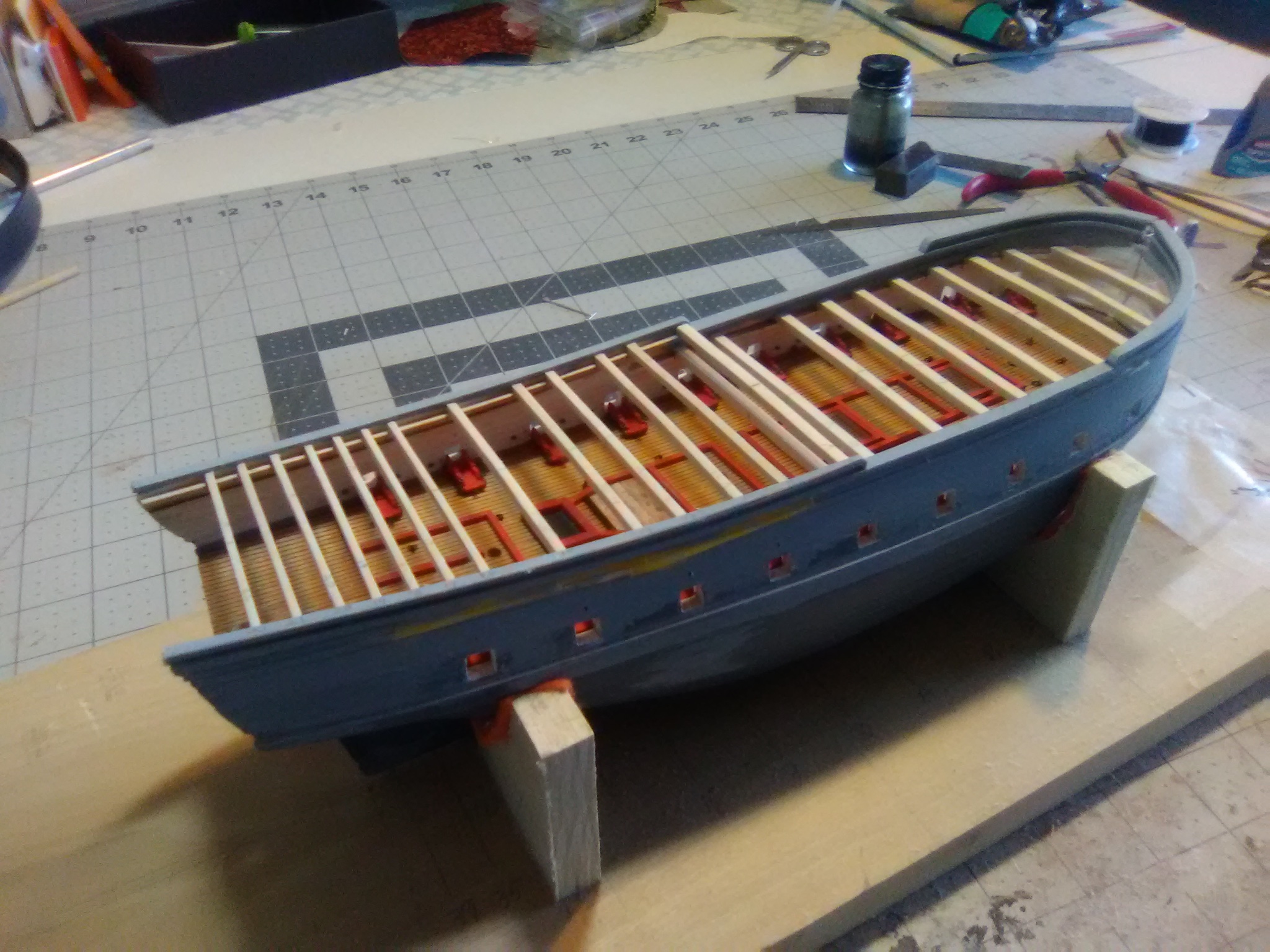
Deck Beams All the deck beams have been fabricated - still have to stain & paint them, they won’t be installed until all the guns have been rigged. A couple of notes regarding the beams and deck planking for those who may build this kit: There are 2 options which you have to choose from at this point in the build 1) plank over both decks completely using the scribed decking sheets or 2) leave some planking off to view the gun deck. If you decide to leave some off, like I will, then you have to decide at some point whether you will cut out pieces of the decking sheets (see photo from BlueJacket on post# 27) or install individual planks like I hope to do. Either way you will have to install some deck beams If you go with the total plank over then you can use 1 size of wood for all the beams 1/8” by 1/8”. As far as number and placement just make sure you place one on each side of the mast locations so you can install mast partners to give the masts support. You will also want to avoid placing beams where there will be any thru-deck penetrations (i.e. the 3 masts, 4 bitts, galley stove chimney and the companionway ladder). The placement of the forward most quarterdeck beam and the aft most main deck beam is very important, both for their fore and aft location and so that the upper (quarterdeck) beam is directly over the lower beam since they will form the 1/4” (2 scale feet) “step” between the decks If you go with the “reveal” option then since some of the beams will be visible there are a couple of considerations: although all the beams will be 1/8” high (thick) there are 3 different widths called for in the plans (but not mentioned in the instructions) 1/8 x 1/8 is needed for the main deck beams and the forward most quarter deck beam. The next 5 quarterdeck beams moving aft need 1/8 x 3/32 wood, and the 7 aft most quarterdeck beams need 1/8 x 1/16” strip wood. all of the quarterdeck beams rest on the inside of the cap rail so be sure when adding the fancy rail and it’s cap rail to leave room for them all the beams, but especially the quarterdeck beams, should have a camber sanded into them so that the outboard thickness of each beam is 3/32” otherwise the quarterdeck planking will not lay flush with the upper cap rail The main deck beams can rest on either a shelf, like mine do which is the easy way or you can make individual knees. If you do not plan on making the beam ends visible then there is no real need to go thru the trouble of making knees One “gotcha” or at least “gotme” is that while the aft hatches on both decks are in vertical alignment, the forward hatches are not with the main deck hatch almost 1/2” (4 scale feet) aft of the one on the gun deck. When laying out the beam locations make sure you reference them from the foremast hole, not the gun deck hatch or you will not have enough room on the forecastle for all the stuff that has to fit up there


- 142 replies
-
- 6
-
-
- alfred
- solid hull
- (and 2 more)
-
Gary, your use of mock-ups and comparisons like the one above is really educational for the rest of us. Your results show what prior planning and thought can accomplish. Keep up the good work!
- 370 replies
-
- 1
-
-
- Model Shipways
- Confederacy
- (and 1 more)
-
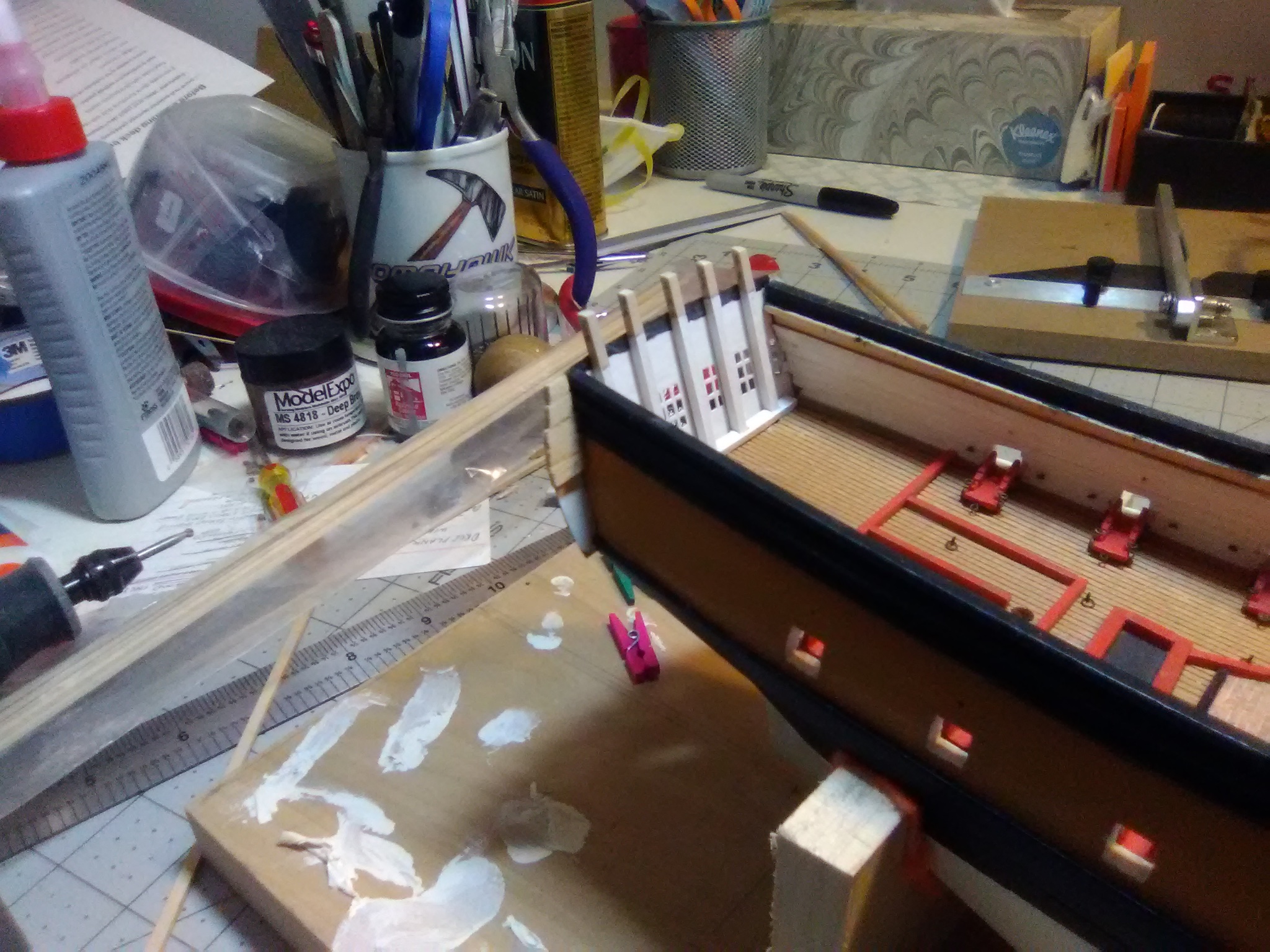
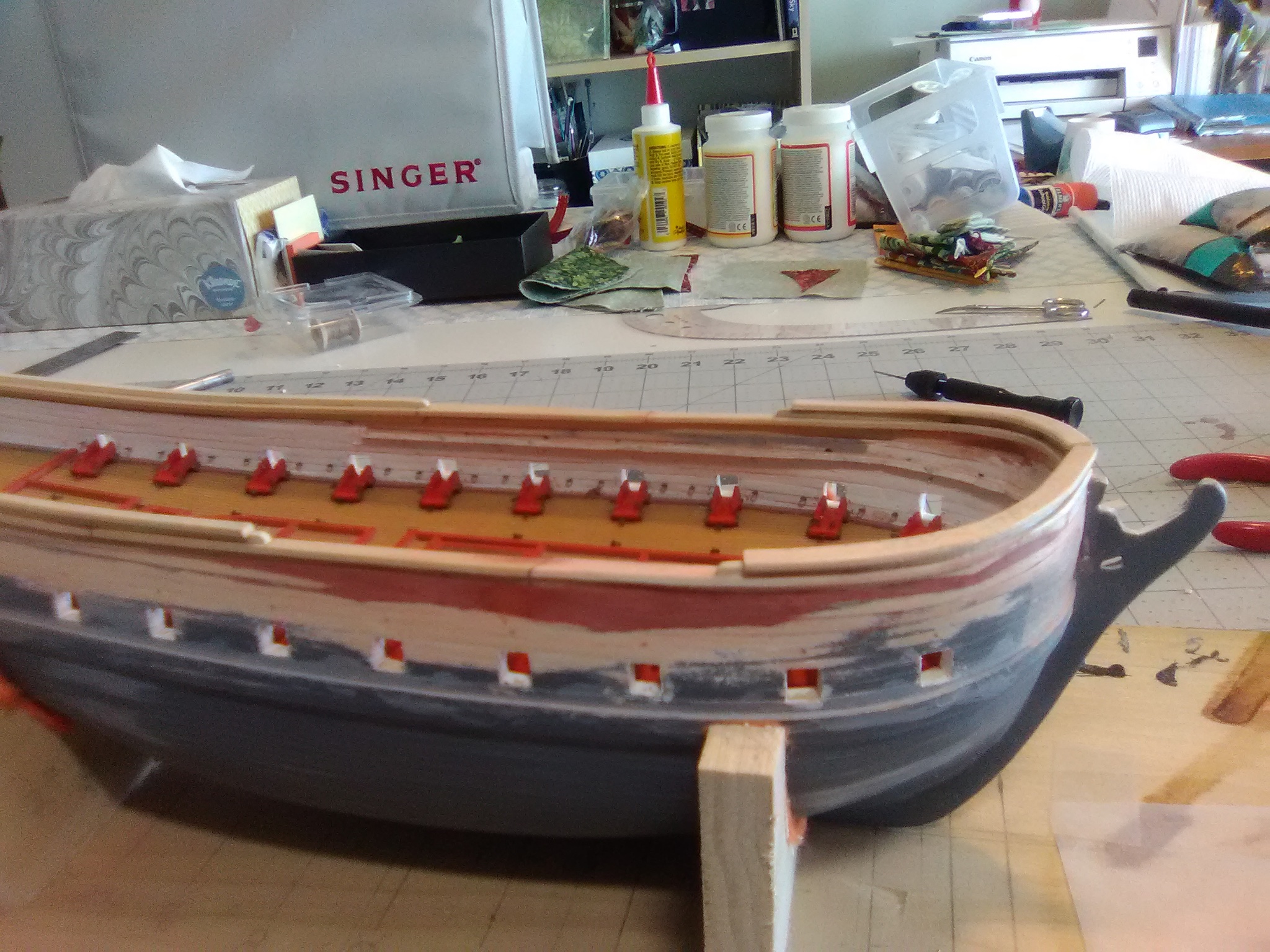
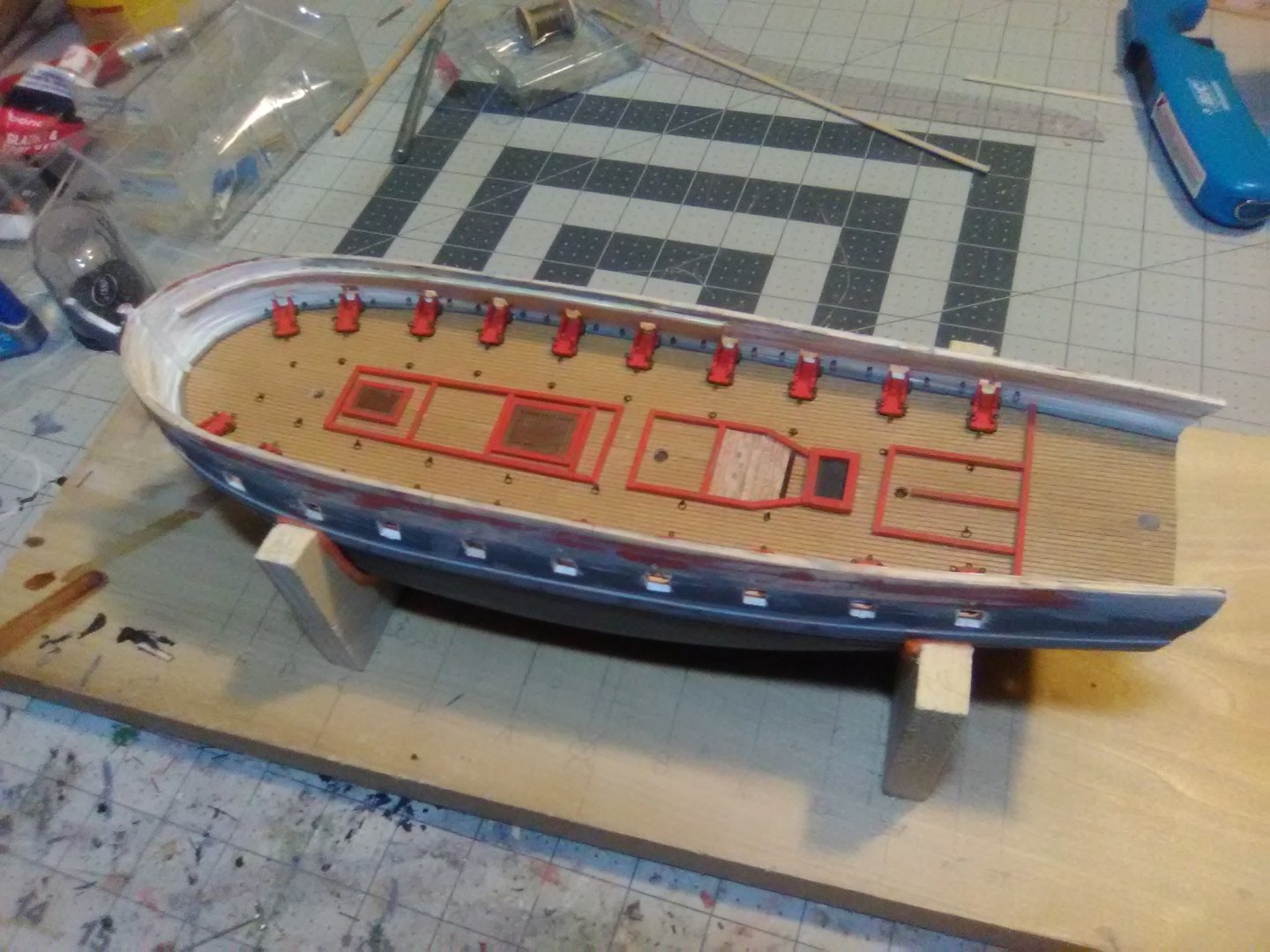
Bulwarks and Cap Rails After add ing the bulwark extensions I added the cap rails all the way around and the fancy rails and their associated cap rails along the quarterdeck and around the bow. Important! The ends of the deck beams will rest on the caprails and fancy rails (see 3rd photo below and post #34) so when fitting the rails leave enough on the inboard sides to support the deck beams. With the rails in place I’ve started making the deck beams: After the deck beams are done I’m going to take a crack at adding the transom.


- 142 replies
-
- 7
-
-
- alfred
- solid hull
- (and 2 more)
-
Thanks for the kind words. Since the hull is pretty small, only about 11 inches long, shaping it was not too difficult and did not make a ton of sawdust like a larger one.
-
Fitting out the Gun Deck Thanks to a suggestion from Nic, the owner of BlueJacket, I may have a solution on how to rig the small guns without spending the next 10 years doing it. I’ll explain it when I get to that point which is still a ways down the road. In anticipation of rigging the guns their carriages have been fitted with eyebolts for the in and out-hauls (the breeching ringbolts will be added when the breeching lines are), as have the bulkheads and the decks. The carriages have all been pinned to the deck per the instruction’s recommendation. Note from much further down the road: I recommend that when pinning the carriages that you also pin the gun barrels at the same time, using the same piece of brass rod. Although the barrels don't stick out through the gunports very far, there will be plenty of opportunity to push them off the carriages while working on the hull and decks. If I had done that at this point in the build it would have saved me a lot of aggravation later on. Next up will be raising the bulwarks, adding the cap rail and the fancy rails. It will be good to deal with wood again after all this metal and wire.

- 142 replies
-
- 6
-
-
- alfred
- solid hull
- (and 2 more)
-
Hey Dan, glad to see a build log for this kit. Are you going to be making it Radio Controlled?
-
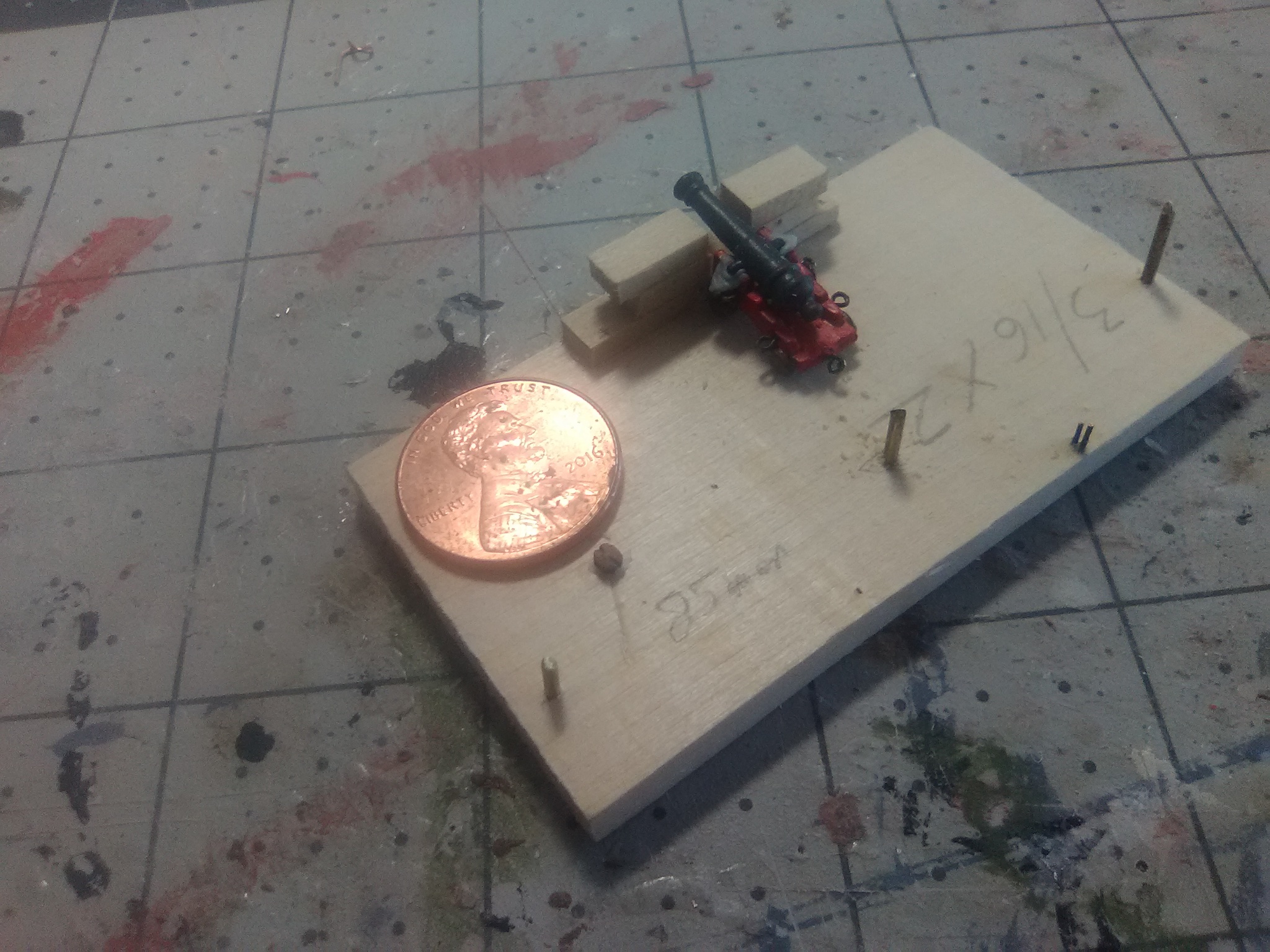
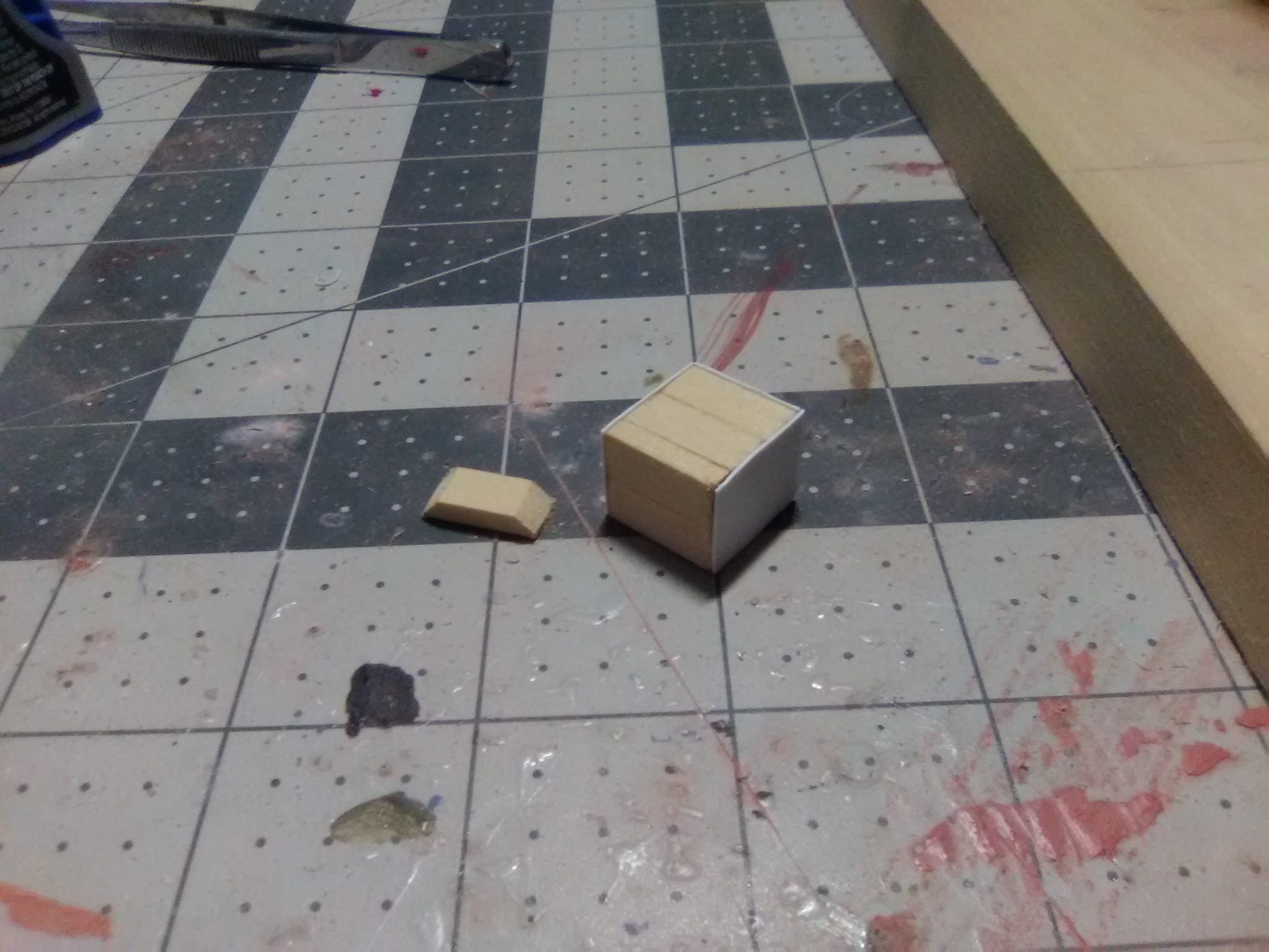
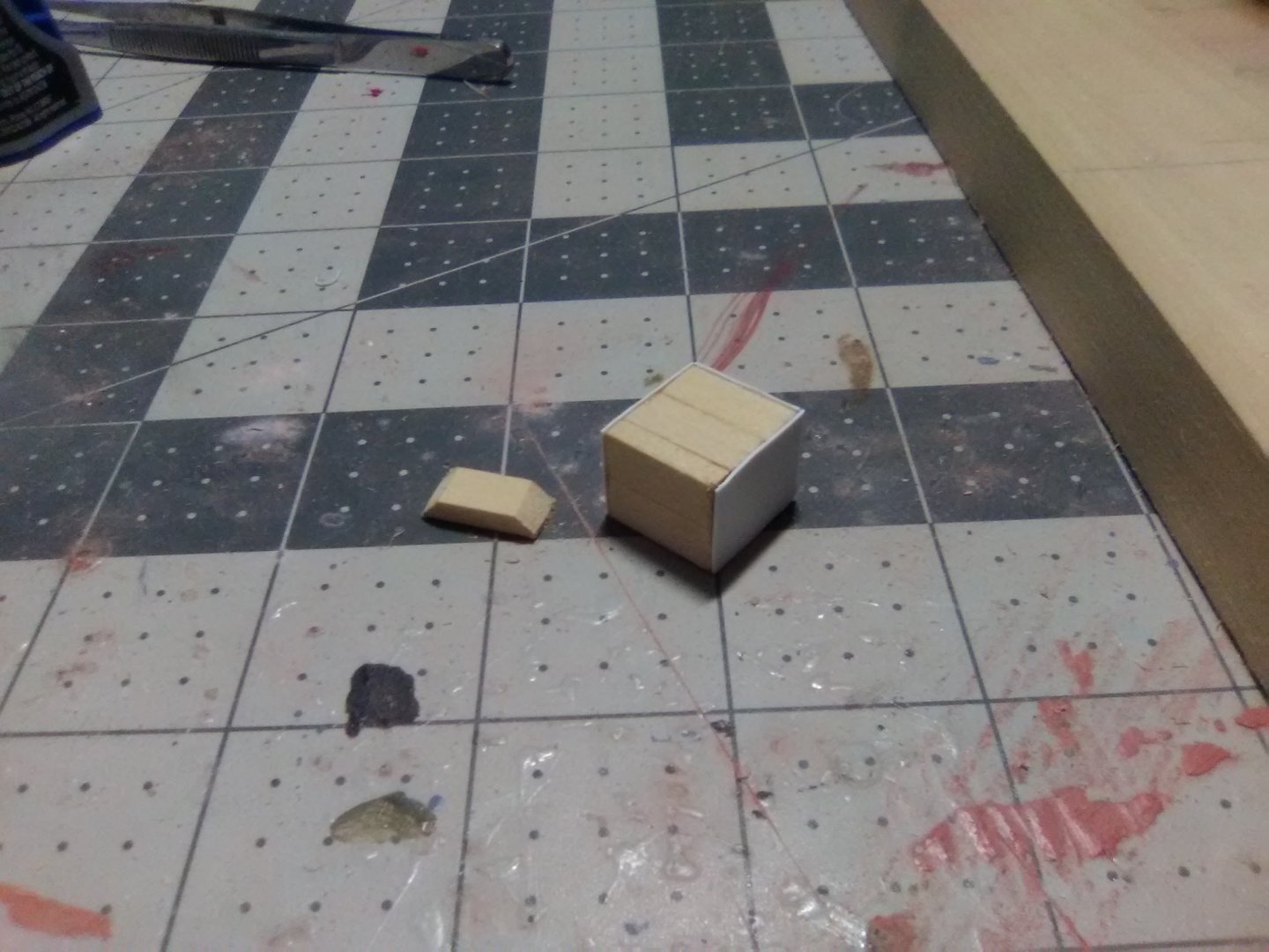
9 pounder guns I’ve been busy on the model but not much to show for it, and with more aggravation than I deserve. I’ve started to work on the 9 pounder guns for the gun deck. The kit provides nicely cast brittania barrels and carriages. Although there is minimal flash and seam marks on them their small size makes for some tedious filing and then I drilled out the barrel muzzles and holes in the carriages so they can be pinned to the deck per the instruction’s recommendations. I then had to decide how much rigging to put on them given their size and the fact that even with some deck planking left off of the decks above them they will still be only indirectly viewable and in “shade” to boot. I built a little gunport mockup to see how much line I would need for the breeching lines. I ordered some 2mm wood blocks from Model Expo, the smallest on the market. After a frustrating hour I was able to get the line thru ONE block! Sure, I could get thread thru there but that looks way under scale. I also need smaller wire than I have on hand to strop them so that’s on order. The little brown dot next to the penny in the below photo is one of the blocks. They do have 2 holes in them and grooves for the stropping. I decided having to do 80 of these for the in-haul tackles for 20 guns would be more fun than I am willing to put up with, particularly since the breech lines will largely cover them up anyway. I’ll probably try to use them on the 6 3 -pounder guns on the quarterdeck but not down on the gun deck. Leaving off the in-haul tackles still means each carriage has to have 3 holes drilled in them (2 for the breech line guides and 1 for the out-haul tackle). So all of that is done. I wanted to put together the 120 ringbolt/split combinations needed but when I ordered more 3/32” split rings from Model Expo they sent me ones that were smaller and thicker than I previously received from them - too small to work for this. I sent them and e-mail & photo and they are going to look into it but I’ll have to make about 80 split rings myself (sigh). My final problem is with the Postal Service. The instructions call for some sizes of wood that are not provided by the kit (I’ll let Bluejacket know which when I’m done) so I ordered it from them. Unfortunately my shipment made it most of the way thru the postal system and then disappeared. I’ll give the Post Office a few more days and then reorder the wood. Good thing I’m in no hurry with this build.

- 142 replies
-
- 5
-
-
- alfred
- solid hull
- (and 2 more)
-
Looking forward to watching this build! Thanks for the tutorial on sardine fishing - you could have fit what I knew about it into one of their cans.
- 100 replies
-
- 3
-
-
- pauline
- BlueJacket Shipcrafters
- (and 1 more)
-
Glad to see a build log for this kit. Good luck and have fun.
- 32 replies
-
- 1
-
-
- Jefferson Davis
- Bluejacket Shipcrafters
- (and 1 more)
-
Just getting caught up with your build. Thanks for taking the time & effort to document how you rigged those small blocks, that will be a real help for me when I have to do 2mm ones on my ALFRED build. Keep up the great work.
-
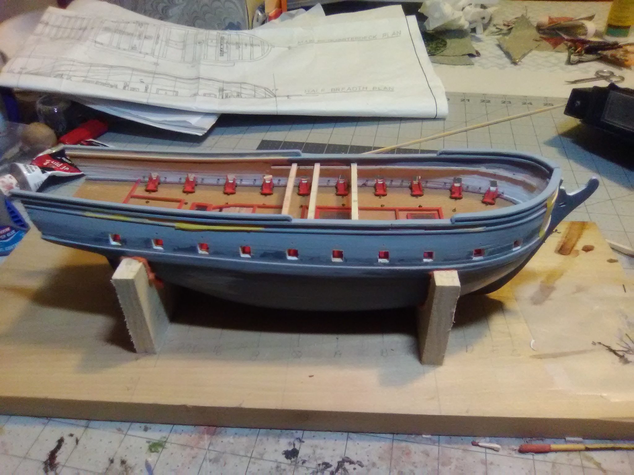
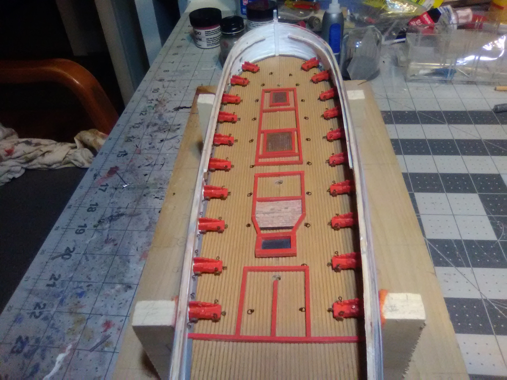
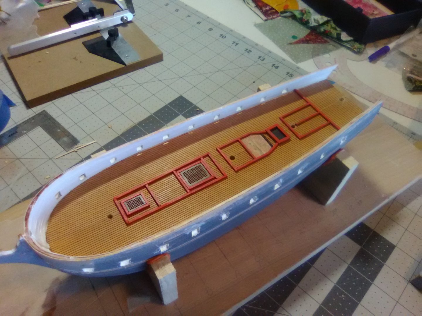
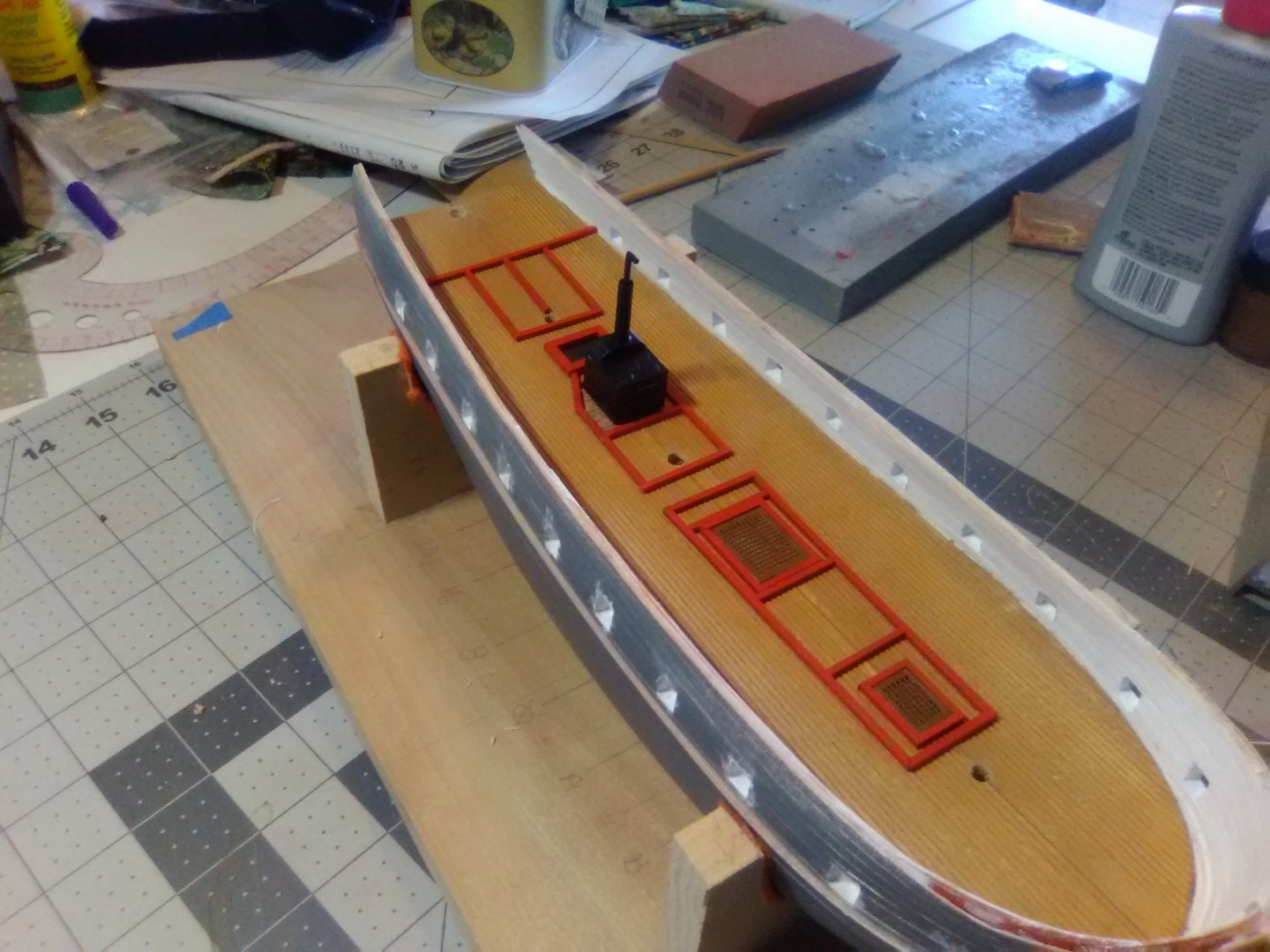
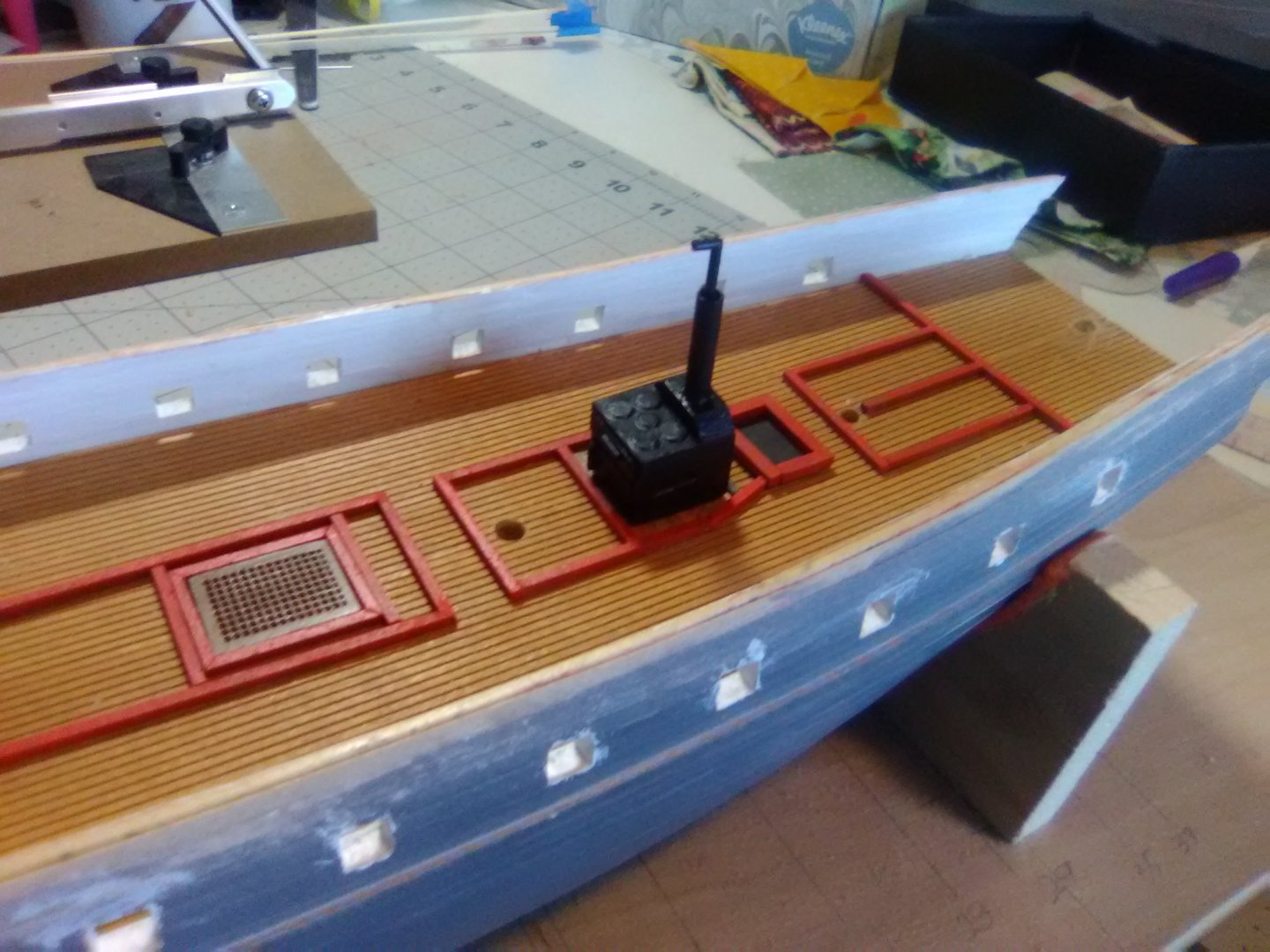
Fitting out the gun deck The hatches and coamings (which serve as the footings for the bulkheads and screens that were removed when the ship was cleared for action) have been installed. Although I plan to leave some planking off on the upper decks I’m not sure how much of the stuff on the gun deck will be visible since it will likely be pretty dark down there. I’m also not sure if I will fabricate any of the bulkheads, maybe the one for the great cabin but that’s about it. The galley oven is scratched out of material that stacks together for the right dimensions and then faced with sheet plastic(I’m lousy at trying to build a 6-sided box where everything is square). The oven (or caboose) is just dry fitted since I may have to adjust its position a little to work around the deck beams.
- 142 replies
-
- 6
-
-
- alfred
- solid hull
- (and 2 more)
-
The Pauline looks like a great kit, I hope you do a build log since there hasn't been one for that kit yet. Good luck!
- 87 replies
-
- 2
-
-
- bluejacket shipcrafters
- red baron
- (and 3 more)
-
Paul, I guess open boat kits could be called POB or POF. They are usually built as POB (upside down over the tops of temporary bulkheads that are removed after the planking is finished - leaving the "frames" in place). You can look at build logs for Model Shipway's 18th century longboat to see what I mean. From a strictly planking viewpoint there is no difference between POB and POF but POBs are usually easier to build because you don't have to build the frames too - which might require more shop tools than you have (certainly more than I have). I recommended a boat rather than a ship because the planks are bigger and fewer, and if it is"clinker" style like most of them the planking is a little easier too. Another plus is most boat kits are cheaper and smaller than ship kits, and don't need to be cased. Spend some time looking around build logs here on the site and I'm sure you will find something. The catalogs from BlueJacket and ModelExpo are worth a look too.
- 87 replies
-
- 2
-
-
- bluejacket shipcrafters
- red baron
- (and 3 more)
-
Great job!! Looks nothing like my 1st build! You have given me a serious case of lobster pot envy - your pots and floats are very realistic. It's amazing how details like those can really bring a model to life. As far as you next build goes you might want to consider a planked boat, particularly one with an open interior like a rowboat, wherry, crabbing skiff, etc. Something not too expensive because it will be your 1st planking build and should be treated as a learning experience, albeit one that you can put on the shelf. Once again, nice job!
- 87 replies
-
- 5
-
-
- bluejacket shipcrafters
- red baron
- (and 3 more)