wefalck
-
Posts
6,644 -
Joined
-
Last visited
Content Type
Profiles
Forums
Gallery
Events
Everything posted by wefalck
-

Harriet McGregor by Boccherini
wefalck replied to Boccherini's topic in - Build logs for subjects built 1851 - 1900
The shackle looks nice as well ! I meant this kind of saw blade: https://www.ebay.de/itm/201975383662?hash=item2f06abc66e:g:GC4AAOSw-29ZWxFd It is sold by the metre in various diameters from 0.26 mm upward for fretsaw work on semi-precious stones. They are not cheap though, 8€ to 10€ the metre, but you can hold it in an (older, as diamond may mar the jaws) pin-vise. -
Mostly overlooked by modellers, but the shipwrights and boatbuilders of old took great care and pride in finishing their work, running down a moulding-plane here and there. It also had the practical purpose of rounding off edges to prevent splintering. Not easy to reproduce below certain scale, which is probably the reason, why it is rarely reproduced by us modellers.
- 433 replies
-
- 6
-

-
- open boat
- small boat
- (and 1 more)
-
As I said above, solved mystery: https://en.wikipedia.org/wiki/Sailing_stones
-
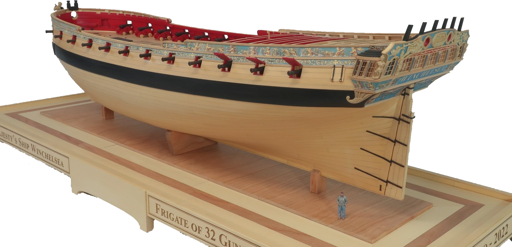
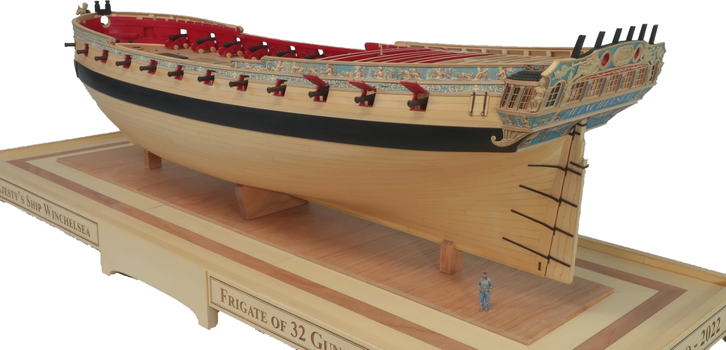
With e.g. Photoshop you can get rid of the background: ... o.k. it bit more fine-tuning would be needed for the shadows underneath the stand.
-
Harriet McGregor by Boccherini
wefalck replied to Boccherini's topic in - Build logs for subjects built 1851 - 1900
I know these rabbit holes all too well ... Looking good the blocks, so the tumbler works. If you have a file fine enough, or some diamond-coated round fret-saw blade or a very sharp chisel, I would round off the edges of the holes to simulate the sheaves. It looks better, when the ropes don't come out of the holes with a sharp bend. -
I gather you scrape off any glue squirting out while it is still wet - hence also the wetting brush ? What kind of chisels do you use ?
- 433 replies
-
- 4
-
-
- open boat
- small boat
- (and 1 more)
-
Re. sliding stones: I vaguely remember that there was a paper in Nature on it in the early 1990s and in the meantime they have hit Wikipedia: https://en.wikipedia.org/wiki/Sailing_stones Agree, there are striking images on that photographer's Web-site. I gather, if you live by it, it needs a fair bit of self-promotion ... lots of competitors.
-
Yes, one can 'point' the focal point on my iPhone SE too, but that is not enough, one needs to put a particular element on the object into focus and then you are dependent on how the autofocus reacts to the object's area. For image-stacking one would need to move the focal plane step by step through the object and this you can really only do with a manual focus ring. In the house, including my workshop, we have gone virtually completely LED now, mainly filament bulbs. In the workshop I installed an indoor LED floodlight over the workbench and have a moveable architect's lamp with a strong LED bulb in it. The colour temperature of illumination in a workshop can be quite an ideological matter among modellers. Some people go to great lengths to install 'day-light' (5500 K) illumination in their workshop, paint walls bright white etc. Personally, I wouldn't like the hospital feeling. My models typically would be seen with artificial light, rather than in bright day-light, so I rather would go for something that looks good under 3600 K. With the possibility to set the way how the camera interprets the light or to adjust the light temperature in Photoshop et al., the colour temperature of the illuminating light is also not so critical anymore, compared to the days of film. 'Warm' LEDs, however, are about 10% less efficient than 'cold' LEDs, because the yellow filter that is painted on them absorbs some of the light. One thing to avoid, if possible, is to mix sources of light of different colour temperature, because the resulting (local) colour tinting is difficult to correct.
-
True, but modern cameras, or rather the software built into them, comes with so many bells and whistles that I tend to forget many of them. My philosophy has been, since I went digital, to shoot 'neutral' images as a starting point for post-processing. So, I am mostly not using any of those built-in exposure-correction programs. However, if there is a risk of underexposure in the shadows or overexposure in the highlights, I would try to adjust this with selective metering etc. As I said above, if the pixels don't have any other information but black or white, there is not much scope for post-processing. Talking about post-processing, a feature in Photoshop I am using frequently is the geometry correction. In the old days one would have called this Scheimpflug-correction of converging lines. Some studio cameras have the possibility to shift and tilt the lens and one can do this also in the darkroom. Now it is easy to correct distortions digitally, but one has to be aware that it degrades the image to some extent. However, pictures look so much more professional, if lines that are vertical also appear so on the image. I also use this e.g. in museum shots, when I have to take an oblique position to avoid reflections from surfaces of paintings or glass cases. I inherited from my father a Nikon lens in which the actual lens can be moved sideways by a few millimeters to give you a greater depth of field, when taking oblique shots. This is useful for table-top photography. However, I am not using it very often, as it pre-dates the digital age and does not transmit the lens data to the camera body. Much of this serves to work around sub-optimal photography situations. A professional, of course, would take the time and has the resources to make lighting and other arrangements. As amateurs we mostly cannot do this, unless we work in our own 'studio'. Another point of DSLR vs. iPhone: on the DSLR you can switch to manual focus and set the focal plane to where you really want it to be, tweaking the autofocus on a smartphone is difficult to impossible.
-
Not sure, how much of it actually is genuine 'tongue in the cheek'. There is a lot of tech-stuff that is likely to frighten off many people (or perhaps sends them to Wikipedia et al.) and he keeps telling people that you need the artistic vibrations, which kind of belittles other people's work. There is also 'advice' on his site that in principle is correct (say on shadows and highlights), but virtually impossible to put into practice unless you have a crew assistants around and a van full of equipment or work in your studio. Yes, I like the clarity and vibrance of his shots from the SW USA - but then unlike Scotland and here in Paris, the area is bloody dry with not that much haze in the air. But then luminance and vibrance and strong colours is not everything. He claims that the vibrance is due to film he used, but I am quite sure that some post-processing was done on the images on the Web-site or on the newer shots in the camera settings. Photoshop, even in the amateur edition as 'Elements', is quite powerful. The tweaking one did in the darkroom can be done now with visualising immediately the results - I had been waiting for that for decades. Of course, if a pixel is black (dead shadow) or white (burnt out high-light) there is not much room for tweaking. Anyway, we are veering off the subject, which is not the critising of a particular photographer, but getting better studio shots of our models. BTW, if you are interested, here are my own modest attempts: https://www.imago-orbis.org
-
Is there still a strake/wale to go on now ? I am wondering, because the transom stern-post seem to be above the level of the frames.
- 433 replies
-
- 2
-
-
- open boat
- small boat
- (and 1 more)
-
Yes, of course, I am shooting in RAW only. With post-processing a lot of the contrast problems can be compensated for, but even with the various program options and selective metering etc. I don't seem to able to shoot high-contrast images, such as a moon at night for instance. The iPhone seems to do this without tweaking ...
-
Just wondering, whether it wouldn't be easier to put the stanchions on first and then push them down into their holes one by one. Some stiff steel or molybdenum wire might help as well.
-
When I started my photography life in the early 1970s, I was lucky that my school organised a practical course with a local photography club, where we learned the basics of b/w processing and the basics of photography in general. I also read a couple of technical books back then, my father had. The school had a darkroom for the pupils' use and I got the equipment to process films at home. Never got into colour processing and printing, using only slide-film - for the last 25 years of analogue photography I used Fuji Sensia 100. Eventually got a slide scanner and Photoshop, but when camera sensors became big enough to allow A4-sized prints, I went fully digital in 2006. Digital image processing allowed me to do all the things I always wanted to do to my slides. Just looked over this Ken Rockwell's Web-site. The guy seems to have his nose pretty much up in the air and he prides himself being an 'artist', I feel. His pictures are colourful, but not that much more. I am currently using a Nikon D5100 DSLR, but find that it handles stark contrasts less well than my iPhone SE, in spite of all the buttons you can turn. That's one of the reasons, why I am using the iPhone for workshop pictures, where I don't have much options to control the illumination. Rockwell seems to use a lot long exposure shots, up to 1 min of exposure time or so. His films must be pretty good not to suffer from the Schwartzschild-effect. Nowadays you can ramp up the sensitivity, but then you end up with 'white noise'. Still, for workshop-shots I often go up to ISO 3600 - you can eliminate it in Photoshop sufficiently for posting work-in-progress pictures in fora.
-
There is a sort of feeling among many people, artists, museum conservators, modellers, that old methods are better and time proven, but time has proven that some of the practices used in the past are not as good as one might think. Today, our scientific understanding of materials and their interactions is much better than it was 50, 100 or even more years ago. We can have a more rational approach to materials use and don't need to do something simply because that it is how it was done always. Doing things the way they were always done never was a good reason for me. A reflection on why something is done and for what purpose is always helpful and helps also to better judge 'advice' from books or fora.
-
Synthetic rigging material suffers little, if at all from varying degrees of ambient humidity and, therefore, changes in length of the fibres ...
-
Shoemakers do it regularly, but they don't use real beeswax, but rather some sort of pitch with wax mixture. It comes in little blocks and thread is drawn between the finger and the block, the friction heat helping to impregnate the thread. However, when sewing shoes, some waterproofing makes sense. If I felt compelled to use wax for historic or other mystic reasons, I would use a hairdryer or a hot-air gun to melt the wax into the thread at least, before using it. It always amazes me, how certain age-old practices are perpetrated simply because they are age-old practices and therefore must be good ...
-
... and to keep the paper from slipping, when you put some small items for photographing there (how do I know this ).
-
The jury is still out on longevity, but even museums nowadays seem to prefer polyester threads, such as Gütermann's Mara (which is what Chuck Passaro seems to use for his ropes). There is little or no fuss on such ropes and no need anymore to mess around with dust-catching tacky bees wax.
-
My father had two lightweight microphone tripods for this kind of tasks, they had the camera thread at the head, so one could screw the lamps onto them. This gives you more freedom to move them around.
-
How do you want to tie the stiff, pre-soaked threads then ? Also, you may not be able to tighten the knots sufficiently with the stiff material. I would advice against pre-soaking.
-
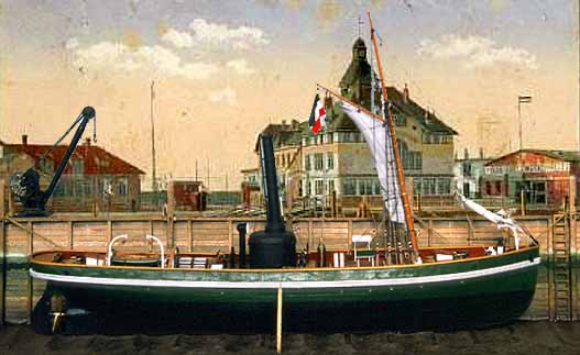
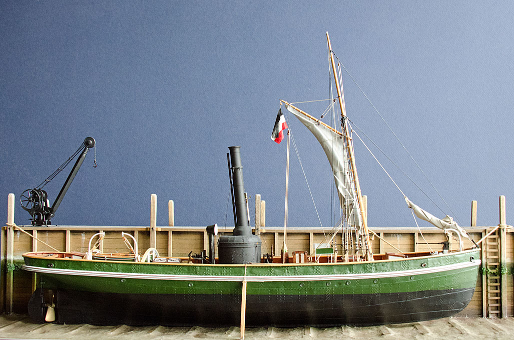
A solid green or blue background, e.g. photoboard, is also useful, if you want to remove the background in Photoshop in order to place the image in front of something else (like the blue-screen technique used on TV). Most (historic) models do not have one or the other of these colours so it is easy to select and remove them. Below an early attempt using a blue background and then placing the image in front of a scanned photochrome postcard:
-
The problem of trying to take more sophisticate photographs with a smartphone is that it is difficult to judge the focus on the screen and due to the autofocus it can be difficult to impossible to coerce it to focus on a particular detail or focal plane. Therefore, taking the controlled focal plane images for focus stacking is difficult (at least on my iPhone). In my experience, a white background is problematic because most cameras have difficulties with the then high contrast ratios. A neutral grey or contrasting coloured background reduces the contrast between the object and the background. Of course, a strong (diffuse) light source from the direction of the camera also helps to reduce contrasts.
-
Home, bench top laser cutters.
wefalck replied to Bill Hudson's topic in Modeling tools and Workshop Equipment
Thanks ... but 3D printing would have been probably better for this. As with all tools and methods, they have their specific areas of application and 'one size does not fit all'. 'Light' laser-cutting is probably best suited for flat and intricate parts that would be difficult to hold and manipulate. In this sense it can replace photo-etching to some degree