


wefalck
-
Posts
5,571 -
Joined
-
Last visited
Content Type
Profiles
Forums
Gallery
Events
Everything posted by wefalck
-
 Yep, I had to do this on the wooden stairs in the house after school once a week …
 -
PS. as our posts overlapped: - drill-chucks are made for drilling and do not like to take side-loads as occur in turning; they would be imprecise at least and can outright dangerous, when the loads are too high. Do not entertain this idea. - in hobby-turning one would not use any cutting-oil; brass and aluminium are always turned dry and for steel nether the turning speeds nor the cutting depths would lead to so much heat generation, that cooling of the tool-tip is needed - which is the purpose of cutting fluids here, not lubrification. Cutting fluids are for production lathes. On milling machines the situation is somewhat different, here you will need lubrification for steel, but not for brass normally. As to chucks: I believe there are hollow (China-made) MT2 to ERxx adapters available on ebay et al. This arrangement would be perfectly ok for working with bar-stock that passes through the whole length of the collet. If the material is shorter than say half the collet length, then there is a risk that it is being pushed out and the collet is damaged due to overtightening. If my memory serves my right, such adapters go at around 20US$ and collets, depending on size at 2 to 3 US$ a piece - I have bought such collets for use in lieu of a drill-chuck on my watchmakers lathe and as cheapo as they are, they are perfectly adequate for our needs. 4-jaw-chucks are very precise for centring material that has been already machined, but a pain to set up. You will also need a dial-indicator and stand for this. I wouldn't bother with a 4-jaw-chuck and unmachined round stock. Remember also that unless you need to re-chuck a piece (say to work on both ends), when working from bar stock, the quality of the chuck/collet is pretty unimportant. All machined surfaces will be concentric to each other.
-
There are two elements to engage the backgear: - there is a pin or other type of lock that engages the small gear on the spindle, which has the pulleys permanently coupled to it, with the large gear on the spindle; in this situation the lathe spindle is driven directly. - if the rear gear/pulley is not locked to the large gear, it idles on the spindle; the ball-handle lever on the backgear spindle works on excentric bearings, which allow the backgears to swing into mesh with the gears on the lathe-spindle. If you lock the gears on the main spindle and swing the back backgear into mesh, the whole system is locked. When you then start the motor, either the belt will slip on the pulleys or it may sheer-off the locking pin. If you suspect the latter is the case, you have to dissamble the whole headstock and drill out the remains of the pin. I have taken anything with Babbitt-bearings apart, so I wouldn't know, how to deal with them. I am sure you can find some advice for this on the Web. Normally, there would be a nut on the back of the spindle and a corresponding lock-nut, most likely to be worked with a C-spanner. These serve to adjust the end-play. If you take out the nuts, you can pull out the spindle to the front. There would also be a grub screw to loosen that locks the large gear onto the spindle.
-
On smaller boats the peak would have an eye in the boltrope that then is slipped over the end of the sprit. Indeed, that is the advantage of a spritsail, that is collapses quickly, once you lift the throat out of the sling at the mast, a kind of safety feature on small boats. The boat in the middle of van de Velde's painting seem to have a sort of standing sprit and the sail is hoisted with a peak- and throat-halliard running through blocks attached to the spar and the mast respectively. The sail still can be collapsed by lifting the sprit out from the sling at the mast, as is shown on the boat to the right in front of the larger vessel. However, all the boat shown seem to have tackles to manage the lower end of the sprit. This arrangement allows to move the sprit to a more horizontal position, which presumably balances the sail area better relative to the boat when running before the wind.
-
Talking about photography: when I am photographing objects with a high contrast ratio and when the surrounding illumination is likely to drown-out the shadows in other parts, I do not overexpose, but I rather manipulate the contrast range in Adobe Photoshop. Here I can 'lighten' the shadows and darken 'lights' (if needed), and then reset the contrast. From an artistic photography point of view these wouldn't be 'good' pictures, but here we are doing sort of 'technical' photography and want to show certain features of the object. This process does not disturb the overall exposure and contrast balance of the image too much and therefore is more pleasing to look at.
-
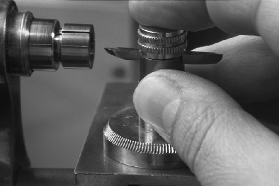
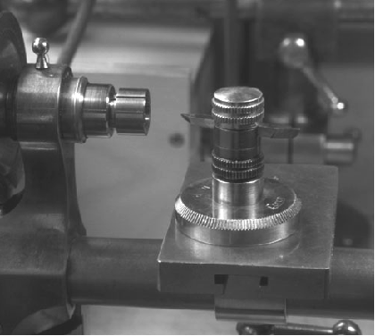
I quite agree that up to the early decades of the 19th century not too many turned parts appear on ships and hence there is not much need to replicate such production processes. However, it also depends on the scale you are working in. If you are working in 1:48 or larger, the pieces are big enough to work on with hand-tools, but at smaller scales it becomes more difficult to achieve the needed precision without machine tools. I know, of course, that there are known miniaturists, who just use a simple lathe if at all. Does the Craftsman really have Babbitt-bearings? That sounds strange for such a small machine tool. Such cheap lathes wouldn't have had ground 'glass-hard' steel- or ball-bearings, but normally had bronze-bearings. Coming back to the original question: not everyone is very dexterous with the chisel or graver on a T-rest, particularly the occasional user. Therefore, at least one bench-lathe manufacturer offered a special kind of 'hand-rest' that would be easily replicated in the appropriate size on a lathe (as pictured on http://www.lathes.co.uk/lorch/page3.html: (incidentally, these are my fingers on Tony Griffith's Web-site ...) You would just need to clamp a metal plate or even a piece of melamin-covered chipboard to the lathe bed as a surface to move around the tool-holder freely.
-
kgstakes, what is actually wrong in your opinion with your lathe ? When pondering lathes it is important to draw up a list of the things and their enveloppe sizes that you are expecting to make. An old rule of thumb is to by a lathe that has twice the capacity you think you need 😉 Apart from that the other end of the size range also needs to be considered. If you are expecting to make (lots) of small parts, a chuck is not such a good option for a couple of reasons: it is less precise than collets and the spinning jaws are always a risk for valuable body parts, such as fingers. As you already have a lathe, you may want to look into a collet-chuck for it (I don't think the Craftsman has an internal spindel taper for collets). They are easy to obtain though ES-collets are more for tool-holding and not so good for work-holding. A 5C collet-chuck would be better. On the other hand, as you have thread-cutting capability on your lathe, you could make a collet-adapter four your own lathe quite easily yourself. You could then make one for WW-horological collets to work with really small parts. An engineer's lathe is not ideal for woodturning, as dust can easily clog the drive spindle. A plain lathe would be better. When you turn wood, you should remove the saddle and apron as much as possible without going so far to disassemble the lathe and cover well the spindle in front of the bed. Dito for the backgear etc. I would tape it up. Otherwise you would need a thorough cleaning session as wood dust together with oil makes a nasty combination that can clog vital parts of the lathe easily. To fashion a T-rest (or several sizes for convenience) should be quite simple. You would need to make a bed adapter that clamps to the lathe bed and to which a stem is screwed that carries the actual tool-rest. On the Internet there should be pictures of the (way overpriced) T-rest Sherline used to sell for their lathes, which should give you design ideas. I think that could be done without needing a milling machine, just using stock materials and simple tools.
-
Perhaps it would be worthwhile to consult LEATHER, J. (1979): Spritsails and Lugsails.- 392 p., London (Granada Publishing). though he focuses more on the later 19th and early 20th century.
-
Oh yes, those reinforced concrete signs used to be something very typical French, but they have largely disappeared together with the concrete 'mile-stones', the rounded top which was painted red (for the 'nationals') or yellow (for the 'departmentals'). The selection of signs is interesting: the one in the lower left corner points to the N13, which is now the A13 and runs past within sight from the house, where I am living currently. The N446 (now down-rated to D446) on the top right corner passes through a pretty area south of Paris, lots of woodland, but it become more open in the area, where sign is located, which must be in Monthlèry, given the distance from Orsay and Versailles. The others in the top row are mostly in the north of Paris, today not so famous areas and quite densly populated, but 70+ years ago would have been more rural.
-
That's quite a process to take out the whole backbone of the boat, while keeping the rest propped up and in shape ... I have seen this done with sections of the keel etc. but not with the whole assembly. Essentially, the frames then were kept in place by the planking alone.
- 88 replies
-
- 3
-

-
- Vigilance
- Sailing Trawler
- (and 1 more)
-
I too will follow this project with interest. Good research and thorough preparations 👍🏻
- 88 replies
-
- 2
-
-
- Vigilance
- Sailing Trawler
- (and 1 more)
-
drilling hole through wire
wefalck replied to BETAQDAVE's topic in Metal Work, Soldering and Metal Fittings
Proxxon offers a very similar model and I have used this without issues for 20+ years. It’s also found in many restaurant kitchens, used to caramelise the sugar on créme brûlee. -
Wouldn‘t there be a safety-valve and some piping that leads the steam safely out of the boat? And: where is the steam for the engines taken off? Is there a steam dome to ensure dry steam is drawn?
-
Yep, you were right Maudslay constructed his first lathe around the turn of that century - I was quoting from memory and that sometimes fails. Still at that time bolts were expensive and the first standardised thread by Joseph Whitworth had only just been proposed (1841).
-
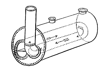
I believe many such riverboats had locomotive-type boilers, rather than than the more complex marine boilers. But this may also depend on the period, I suppose. A locomotive boiler has the firebox at one end, the fire-tubes going through the actual boiler room and the smokebox at the other end, where the flue-gases collect and are led up the smoke-stack. However, the boiler you modelled seems to be a return-type of boiler, where the fire-tubes are U-shaped and return towards the firebox, ending up next to the fire-box, before the flue-gases exit through the stack (see picture below). It seems that two U-shaped fire-tubes are placed into the same boiler, stoked by two fire-boxes side by side: Image from https://en.wikipedia.org/wiki/Flued_boiler. The power of a steam-engine is determined by the surface of the grate in the fire-box and surface of the fire-tubes along with the maximum permissible pressure. The above construction is one of the simplest forms of boiler and would not permit very high pressures due to the large diameter of the single/double fire-tube and the difficulty of keeping the large openings for them water-tight.
-
Deck 'clutter' would have been permitted only during brief periods, namely when being aprovisioned, certainly not at sea. Anything loose will fly around and cause danger to personnel and equipment.
-
A rivet does not necessarily need to be red-hot, but indeed, it needs to be accessible from both side. The planks of clinker-built hulls are rivetted together, but there the rivets are made from copper. During the Viking-age, I think also iron rivets were used, but they tend to rot the wood or corrode due to tannins in the wood. If the iron used for the rivets was sufficiently malleable, one could form the the heads on the outside using cold hammering. Another possibility is, that the bolts were not actually rivetted, i.e. a head was formed, but clenched, i.e. the points were turned over and driven back into the wood. This, howver, requires space inside the hull to work in. Given the realtively blunt bows of the time and that it would be at waterline level, this should have been possible. I gather, the term 'rivetted' refers to the fact that the plates were not just nailed on, as copper sheathing would be, but fastened with through-bolts/rivets. Today, one probably would use coach-bolts for such a task, but at that time threads and nuts were made still individually to match, no norms and only rudimentary thread-cutting technology. The thread-cutting lathe hadn't been invented by Maudslay until somewhat later in the 1840s.
-
drilling hole through wire
wefalck replied to BETAQDAVE's topic in Metal Work, Soldering and Metal Fittings
-
It was a typical shape of a commercial ship of the middle of the 19th century. I have lots of examples from Germany that shows that form until around 1860. Around 1846, I believe, a new bow form, the Aberdeen-bow was developed by Alexander Hall in Aberdeen, which became the forunner of the 'clipper-bow'.
-
drilling hole through wire
wefalck replied to BETAQDAVE's topic in Metal Work, Soldering and Metal Fittings
Yes, the watchmakers called this inter alia 'pivot drills'. And you are right, carbide drills invaded this trade as well, as it allows to drill watch/clock pivots (i.e. the arbors of wheels etc.) without tempering and then re-hardening them, as was done traditionally. -
drilling hole through wire
wefalck replied to BETAQDAVE's topic in Metal Work, Soldering and Metal Fittings
Actually, there are brass-drills out there with a steeper helical angle and differently ground cutting edges ... Another option would be watchmakers' spade drills. These are made for use with reciprocating drills, i.e. Archimedes drills, but also work with electric drills. In the US a source should be Otto Frei (https://www.ofrei.com). Watchmakers, actually used to make them themselves from steel wire. A further option are so-called EUREKA, straight-fluted drills, also from the watchmaking realm. They are stronger than the spade drills, but these days they seem to be expensive and difficult to find. I very rarely use carbide drills for hand-drilling and mainly only in the watchmakers' lathe, where there are very stable conditions with no lateral forces. -
I think it was back in the early 1980s when I last painted any figures at this scale - I have since moved on to 1:87 ... Got what must have been one of the earliest figure modelling guides published in the UK, didn't check but think it is from about 1968 or so - since then techniques have moved on considerably 😉 Today I would use a light grey undercoat, basically to be able to better see any imperfections in sculpting/conversion. The Old Masters used a complementary colour undercoat for skin areas, meaning a light green and then applied the skin-tones in several light washes. The complementary colour underneath makes the skin-tones more luminescent. In my later years of 1:35 figure modelling I used artists' oil-paints for any skin areas (and also for leather details). They could be worked much longer than the Humbrol enamels I used otherwise. However, if you want to work with oil-washes, this requires really long drying times between layers, days or weeks, otherwise the high medium-content of the washes dissolves the previous layer. Today, I basically only use acrylics, mainly from Vallejo (their original business was artists' paints ...). Working with washes is fast, as they dry sufficiently within tens of minutes. Talking about brushes, you may also want to look for so-called 'spotters', this are finely pointed brushes with short hairs. I am not so dexterous or don't have enough practice with standard brushes. The latter can hold more paint, which can be adavantage. Don't go for expensive sable-brushes for working with acrylics. Apparently does not good to them. I use mainly the synthetic ones from the British Da Vinci brand.
