


wefalck
-
Posts
6,642 -
Joined
-
Last visited
Content Type
Profiles
Forums
Gallery
Events
Everything posted by wefalck
-
 Yes, keep your models in a proper atmosphere If there are dramatic changes in temperature and humidity, over time no 'sealing' will help, it will just crack. To my knowledge cabinetmakers did not varnish non-visible, massive parts. I case of panelling, the situation is different, as thin panels may warp, when only one side is treated - a mistake painters in the olds days sometimes made, when they painted on wood, but did not treat the back. Paint will only flake, if not properly keyed into the wood, or when indeed the wood 'works' too much, but so would varnish.
 -
In general, there is no 'finish' needed on wood surfaces that will not be visible once the model is completed. Preserve the wood from what ? It will be inside the model anyway. Of course, if the framing, the ceiling or whatever will be visible, then on an 'artesanal' style model (i.e. not a 'realistic' rendering), you would apply varnish of some kind.
-
As the term implies, a 'finish' does not go onto parts (or rather their respective surface) onto which other parts will be attached, i.e. glued. Glues key better into the bare wood than onto varnished surfaces. Unless something is visible, one does not normally apply any 'finish'. Otherwise, there no general rules, it depends on the individual situation and convenience. Small parts may need to be painted/varnished before they are put into place because it is easier then and one doesn't smear the paint/varnish around and on other parts.
-
I would dare say that it also depends on how rounded the boat ends are. Don't have access to it at the moment, but didn't Eric McKee say something about this in: MCKEE, E. (1980): Clenched Lap or Clinker.- 30 p., Greenwich (National Maritime Museum).
-
Did they really had 'inlaid' (as it was called) linoleum on Russian ships at that time, rather than the sober 'battleship' linoleum (which was also thicker as the domestic one), that usually comes in a dark reddish brown ?
-
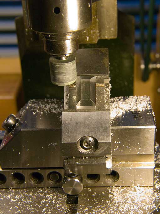
Thanks, Gentlemen ! Tony, it is actually surprisingly easy and fast: you move the rotating silicon bit until it touches the surface to be polished and make one pass; then you advance the bit by 0.1 mm and make another pass. This is usually sufficient. Like for any other such grinding operation, it is important to keep the part moving, otherwise you will get circular scratches in the surface. Here is a similar operation, when I polished the the sloping faces of a Plexiglas block that forms the core of a skylight: Plexiglas is a plastic that polishes very well to a glass-like surface.
- 935 replies
-
- 11
-

-
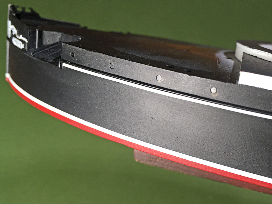
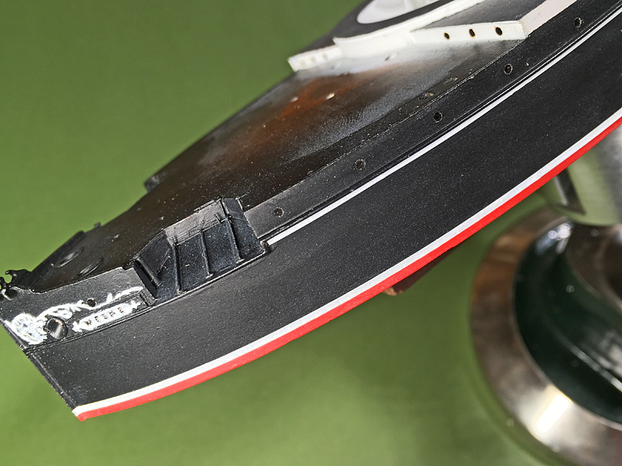
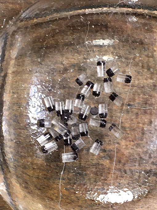
Thanks to all for the continued moral support ! **************************************** Porthole Glazing Following the discussion on ways to make the porthole glazing further up, I looked over all available photographs and came to the conclusion that one does not actually seem to see the bronze frame from the outside. On the other hand, most photographs or their scans do not have sufficient resolution to really see such detail. In order to make my life simpler, I decided to go for solid Plexiglas plugs. I did have 1 mm Plexiglas rod in stock and short sections were cut from this to make 2 mm long plugs. The plugs have to be a bit longer than their diameter, so that they can be inserted straight. The front face was turned flat on the lathe and the back-end was given a bit of a chamfer for easy entry into the pre-drilled holes after which it was painted black using a black permanent marker pen. The pieces were then transferred to the micro-mill for polishing the front face with a silicon rubber polishing bit. In order ensure that the porthole plugs are set at equal depth, a little ‘tool’ was made, a punch with a recess of 0.3 mm depth around the rim. Collection of Plexiglas plugs ready for insertion Glazed portholes Glazed portholes To be continued ....
- 935 replies
-
- 22
-

-
-
I actually thought that our discussion ran around hardening the surface. However, what you are effectively showing here is the creation of balsa reinforced epoxy resin, i.e. a composite material. I am not surprised that the epoxied version is much stiffer.
-
Thanks for your appreciation ☺️ It may be worthwhile to paint the outside of the 'thin wooden edge' in the colour of the deck/waterway to simulate the angle iron that almost certainly would have run around the wooden deck - otherwise it would be rather exposed to splintering. The bollards would have been cast in one piece probably. It seems that the cast iron base often was put onto a wooden base and the whole assembly then was screwed down onto the deck. The screws probably would have gone through some structural element or at least there would have been a reinforcing plate on the underside of the deck. I have seen both variants, that bollards were screwed onto the steel waterways or onto the wooden deck (still having the wooden base-plate). If the bollards sat inside a bulwark and the waterways were cemented to form a gutter, the bollards most likely sat on the wooden deck, as the strain on the bollards would have cracked the cement, leading to water penetration and corrosion.
-
As this is probably going to be a decorative model, you are surely on the right track! It's only good to be conscientious of the artistic licenses one takes.
- 153 replies
-
- 2
-
-
- Ancre
- Bruno Orsel
- (and 2 more)
-
Brass piano hinges
wefalck replied to Chariots of Fire's topic in Metal Work, Soldering and Metal Fittings
Looking at this, I was wondering, if one could make sort of 'snap-on' semi-functional ones, by designing one half with shallow dimples and the other with cone-shape protrusions - the two halves then could be fit together cautiously starting from one end - very much like a zipper ... -
Why masts are square at the top?
wefalck replied to Tommy Vercetti's topic in Masting, rigging and sails
Sorry, missed that 🤭 -
It seems one reason that North American bison was eradicated was, that they were shot by the thousands and just the tongue cut out and the rest of the carcasse left rotting and to the wolfes ...
- 2,699 replies
-
- 4
-
-

-
- heller
- soleil royal
- (and 9 more)
-
Ox tongue is a common cut in Germany. It is usually salted and eaten e.g. with Sauerkraut. We also have a particular sausage made with it. In Canada I had grilled bison-tongue - very tender and lean. The quality of the food for all crew degraded the longer a voyage lasted, as quite soon all the fresh stores exhausted and they had to rely on preserved stores. Not a lot of other options for food preservation apart from salting or drying ...
- 2,699 replies
-
- 5
-
-
- heller
- soleil royal
- (and 9 more)
-
Today, I attended an all-day seminar on 'exchange in experience in restoration' organised by the Musée de la Marine, the Musée des Arts et Metiers, and the French Air and Space Museum near Le Bourget (the old Parisian airport), where the naval museum has its workshops, archives and storage facilities. I was surprised to learn that they use dual finishes on woods and metals: first a varnish and then a wax. Microcristalline wax (e.g. the brand 'Renaissance Wax') seems to be their universal weapon. The varnish seals the wood, prevents the metals from tarnishing, and the wax is a sort of humidity repellent.
-
Why masts are square at the top?
wefalck replied to Tommy Vercetti's topic in Masting, rigging and sails
The original question was 'why are they square', I believe, but nobody seems to have answered that yet: for the simple mechanical reason that the caps and cross-trees do not turn around the tops, when the standing rigging of upper masts is set. -
At this time typically two options were used for planking steel decks with wood: either a gutter was formed with angle iron or a wooden water-way was screwed down along the circumference of the deck. Sometimes both methods were used and the deck planks nibbed into the wooden water-way. On flush decks, such as fore and aft on your ship, probably an angle iron would have been screwed down all along the circumference to protect the edges of the planks. The stanchions etc. then would be set into the wooden deck. Where a proper gutter was formed with two angle-irons, the space between them would have been filled with cement to form a rounded gutter and protect the corners of the angle-irons from rusting. The bulwark stanchions then might be either rivetted to the steel deck directly or through the wooden deck, depending on the width of the gutter. Coming on nicely, the project !
-
Actually, neither of them would have been 'tree-nailed' on the prototype. On the real thing, the planks would have been screwed down with sunk screws and the borehole would be plugged to make it as invisible as possible. The plugs were not tarred, but perhaps covered in some marine glue before driven in. The plugs were cut from the same materials as the planks and with the same grain direction. In this way the deck could be planed absolutely flush before varnishing it. I am watching this nice progress with interest !
- 153 replies
-
- 4
-
-
- Ancre
- Bruno Orsel
- (and 2 more)
-
Overhead trolleys were used extensively also on board of ships to move around ash-buckets, coal-buckets, and amunition. I liked your work on these overhead trolley-ways !
- 189 replies
-
- 10
-
-

-
For a sanding sealer I use a German brand, Clou Schnellschleifgrundierung G1 (https://www.clou-shop.eu/clou-heimwerker/holzlacke/g1-schnellschleif-grundierung.html), but I don't think it is marketed outside the country, so this information might not be very helpful. For acrylics I mainly use Vallejo model color, Vallejo model air (for spray-painting), and again a German brand: Schmincke Aerocolor.
-
Today, genuine turpentine, the one sapped from certain species of pine trees is considered cancerogenic and rarely used anymore by painters etc. The production process is very labour-intensive and it is therefore expensive. Southwestern France was the major producer in Europe, I think. I am not a biochemist or microbiologist, so I may not be entirely correct here, but I think many of the polycyclic aromatic hydrocarbons contained in trees have antimicrobial effects, they are a sort of self-defence o the trees against microbial attacks. People have recognised this a long time ago and the tars were used to dress wounds, particularly also burns. Tar-based ointments were/are also used against microbially caused skin conditions, but I am not sure whether this is pine- or coal-tar, or perhaps both.
-
My point was that anything is possible, but not everything is efficient ... Personally, I use a nitrocellulose-based sanding sealer and then acrylics.
-
Bending Brass Cannon Tail
wefalck replied to Jonathan_219's topic in Metal Work, Soldering and Metal Fittings
Agree with Roger, don't try to bend it, it is far too thick for its length. Even with heat treatment, there is a risk to rather break it. It is correct, that brass behaves the opposite from steel: heating it and then quickly cool it, will soften it. I am not an expert on the period in question, but the 'tail' looks far too chunky to me ... -
Oxhide ropes were used well into the 19th century, particularly in applications when low-stretch ropes are required. Did read part of the Odyssey at school in the original language