


wefalck
-
Posts
6,651 -
Joined
-
Last visited
Content Type
Profiles
Forums
Gallery
Events
Everything posted by wefalck
-
 At this time typically two options were used for planking steel decks with wood: either a gutter was formed with angle iron or a wooden water-way was screwed down along the circumference of the deck. Sometimes both methods were used and the deck planks nibbed into the wooden water-way. On flush decks, such as fore and aft on your ship, probably an angle iron would have been screwed down all along the circumference to protect the edges of the planks. The stanchions etc. then would be set into the wooden deck. Where a proper gutter was formed with two angle-irons, the space between them would have been filled with cement to form a rounded gutter and protect the corners of the angle-irons from rusting. The bulwark stanchions then might be either rivetted to the steel deck directly or through the wooden deck, depending on the width of the gutter. Coming on nicely, the project !
 -
Actually, neither of them would have been 'tree-nailed' on the prototype. On the real thing, the planks would have been screwed down with sunk screws and the borehole would be plugged to make it as invisible as possible. The plugs were not tarred, but perhaps covered in some marine glue before driven in. The plugs were cut from the same materials as the planks and with the same grain direction. In this way the deck could be planed absolutely flush before varnishing it. I am watching this nice progress with interest !
- 153 replies
-
- 4
-

-
- Ancre
- Bruno Orsel
- (and 2 more)
-
Overhead trolleys were used extensively also on board of ships to move around ash-buckets, coal-buckets, and amunition. I liked your work on these overhead trolley-ways !
- 189 replies
-
- 10
-
-

-
For a sanding sealer I use a German brand, Clou Schnellschleifgrundierung G1 (https://www.clou-shop.eu/clou-heimwerker/holzlacke/g1-schnellschleif-grundierung.html), but I don't think it is marketed outside the country, so this information might not be very helpful. For acrylics I mainly use Vallejo model color, Vallejo model air (for spray-painting), and again a German brand: Schmincke Aerocolor.
-
Today, genuine turpentine, the one sapped from certain species of pine trees is considered cancerogenic and rarely used anymore by painters etc. The production process is very labour-intensive and it is therefore expensive. Southwestern France was the major producer in Europe, I think. I am not a biochemist or microbiologist, so I may not be entirely correct here, but I think many of the polycyclic aromatic hydrocarbons contained in trees have antimicrobial effects, they are a sort of self-defence o the trees against microbial attacks. People have recognised this a long time ago and the tars were used to dress wounds, particularly also burns. Tar-based ointments were/are also used against microbially caused skin conditions, but I am not sure whether this is pine- or coal-tar, or perhaps both.
-
My point was that anything is possible, but not everything is efficient ... Personally, I use a nitrocellulose-based sanding sealer and then acrylics.
-
Bending Brass Cannon Tail
wefalck replied to Jonathan_219's topic in Metal Work, Soldering and Metal Fittings
Agree with Roger, don't try to bend it, it is far too thick for its length. Even with heat treatment, there is a risk to rather break it. It is correct, that brass behaves the opposite from steel: heating it and then quickly cool it, will soften it. I am not an expert on the period in question, but the 'tail' looks far too chunky to me ... -
Oxhide ropes were used well into the 19th century, particularly in applications when low-stretch ropes are required. Did read part of the Odyssey at school in the original language
-
A few basic rules and understanding what you are actually doing and why helps to sort the confusion - there are many roads that lead into Rome Just slapping on something, because it was written so in this or that thread is not likely to lead to Rome though ... Assuming that we are talking about 'painted' wood only: In principle you can put any paint on the raw (sanded) wood, but the wood will drink a lot of paint. Also, many paints take a long time to sufficiently dry/cure to let you sand them nicely - and you will need a lot of coats of paint with a lot of sanding in between. The purpose of 'sanding sealer' is to close the pores quickly with something that dries fast and hard, thus allowing you to sand the wood nicely after one or max. two coats. To this end the sanding sealer is 'filled' with something such as pumice powder. Without the filling the sealer would be essentially a varnish. After sanding the filler is essentially invisible, except perhaps on very dark woods. A primer is something completely different and wood is not normally 'primed'. Primers are formulated to somehow interact with the surface they are painted on in order increase the adhesion of the paint used. Thus metal primers undergo some sort of physico-chemical interaction with the bare metal surface that makes them adhere very well. In turn the primer provides the paint sufficient 'key' to attach well. Plastic primers may slightly dissolve the surface and in this way stick to it very well. Again the primer provides sufficient key for the paint to stick well. Personally, I am not using any primers, as I do build only static models that are not handled afterwards. Acrylics applied with an airbrush hold onto most surfaces well enough, when applied in several thin coats. In this sense I often apply the base-coat by airbrush and then continue with a brush, depending on the circumstances. The thin base-coat provide enough key for paint-brushing.
-
ox-hide ?
-
Yes, don't use the fibre-glass brush, it will badly scratch the copper. The plating can be polished using 0000 grade steel-wool. Acetone is a better degreasant than alcohol and also removes CA glue - but use it sparingly, as acetone penetrating the joints could loosen the bond between the hull and the copper. Also do not use CA to stick the copper to the hull - CA is brittle and the bond can break, when there is a temperature change. Perhaps not now, but in a few years time. It is better to use a contact cement. Not sure, what Renaissance Wax really is, but if it is a wax, it may be very difficult to remove, if you are not happy with the result.
-
BTW, Stockholm didn't actually control the trade in pine-tar. It was produced all over the eastern Baltic area and indeed in many parts of Europe, where there are pine-forrests - some days ago I posted on the forum a film that discusses how the Spanish ensured their domestic supply in the 18th and 19th century. The tar or pitch was not only used in a shipping context, but for a variety of other purposes, including medicinal ones. Stockholm exercerted a certain early type of quality control over the tar shipped from there by inspecting the quality and branding the barrels in which it was shipped - sort of 'Made in ...'. The tried to fetch higher prices through quality assurance and develop a sort of quality monopoly. However, pine-tar was successively replaced from around the 1840s on by coal-tar that became available in large quantities as city gas for lighting was installed. Coal-tar behave differently and usually is also darker.
-
I think you have two contradictory requirements there: either you (properly) varnish the copper and it will stay bright for many years, or you don't varnish and it will tarnish to a dull reddish-brown, if not touched. The traditional varnish for metal objects (silver, brass, copper, etc.), including those handled, is what is called zapon-varnish: http://cameo.mfa.org/wiki/Zapon_lacquer. I have model parts varnished more than three decades ago with it and they are still as bright as on the first day.
-
I gather we have a couple of archaeologists here on the forum, I think they should provide their view on the subject of interpretation of such finds ...
-
When rigging, I put a dish with some Lapsang Souchon or a similar smoked tea onto my desk in order to get into the mood 😊
-
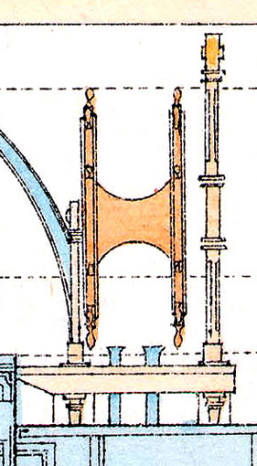
Roger, I am familiar with the concept, but it would not work here, because in order to use it this way, you would need to stand right behind it, which is not really feasible in this case, because the boiler-room casing would be in the way.
-
This also crossed my mind, that it might be a holder for a speaking tube, but no such tube is shown on the drawings of that time. At later times, when an armoured conning tower was installed, the drawings show such pipes. The colour-coding for the enigmatic pillar is brown for wood on the drawing. The navy/-ies seem/s to have used all sorts of from a modern perspective enigmatic devices. Recently I saw on the bridge of the German imperial yacht of that time a frame with slots for cards of some sort. It was explained to me as a sort of note-book on which the courses, distances, speeds etc. of the other ships in a flottilla were recorded for reference.
-
The problem lies in what EXACTLY really is. We don't know, we where not there then, and no written or pictorial records exist. We interpret, in the above case, archaeological finds, with our modern knowledge and logic. But then the knowledge was different and the logic probably as well - we have some archaeological evidence of what people in a particular case may have done, but we don't know what they have tried to achieve and why, and what was the 'normal'. With the exception of one of the Skudelev wrecks, I think, all longboats finds were dressed up for funerary purposes, so we don't know, to what degree they reflect actual practice. Even for many 19th century practices there are no records and we need to back-interpret with our 20th/21st century knowledge. This applies in particular also to naval vs.merchant navy practices. We are so much framed by tax-money funded naval practices, which were often recorded, that we think that this is what they did on low-marging operated and sparingly manned merchant ships as well. Not very likely, as later 19th century photographs seem to indicate. When you look at a modern replica, you look at a set of interpretations of the existing evidence, nothing more. Sometimes these are the best available interpretations and sometimes concessions have to be made, when you actually want a working(!) replica on which you are allowed to put people.
-
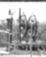
Lou, looking at the only drawing that is available, I don't think it is a break. Pat, it could be an axiometer, but there are no front-views and the only photograph that shows the bridge is too small to show details. I tried to make the model to look like what is seen on the photograph below (ok, it turned out a bit more chubby). The above is a blow-up from this photograph. Unfortunately, this photograph is only known as printed reproduction from a still unidentified publication - I once came across a cut-out page from it, but unfortunately did not buy it on ethical grounds, as I hate people cutting pages from books, hoping that I would find the original book on day ... the picture is rather 'pixelated' due to the printing process.
-
Making Brass Masts for 1/700 warships
wefalck replied to dcicero's topic in Metal Work, Soldering and Metal Fittings
As noted above, no lathe is needed: just make a shallow V-groove in a piece of wood, chuck up the wire into your mini-drill and work away on the way with a sanding stick with, say, 600 grit 'wet-n-dry' paper. Not even a mini-drill is needed, you can just hold the wire between your fingers, turn it by, say, 30° and count the number of strokes with the sanding stick to achieve roundness. -
It seems that the debate goes full circle again ... modern examples are not helpful, as they only reflect the modern interpretation of others and perhaps modern seaworthiness regulatory requirements ...
-
Making Brass Masts for 1/700 warships
wefalck replied to dcicero's topic in Metal Work, Soldering and Metal Fittings
That's too 'cheap' way out and does not improve one's modelling skills -
I think I would concour with your 'personal opinion' !
-
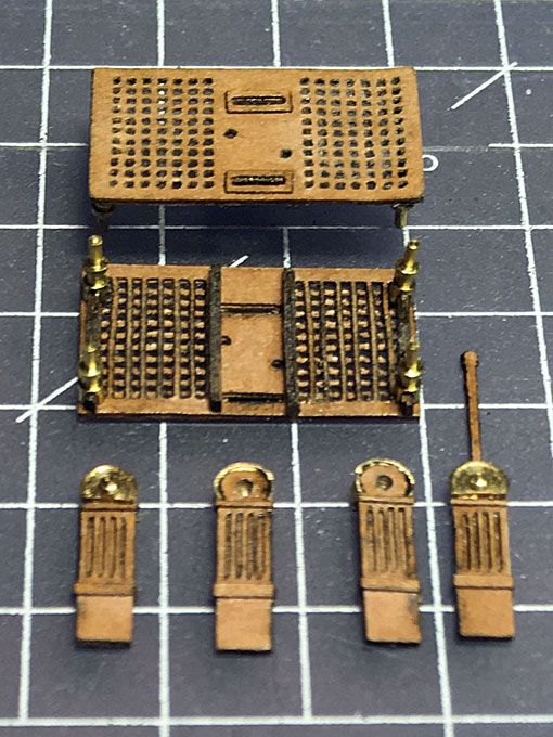
Brian, the gratings are laser-cut in one piece, meaning the actual grating and the coamings. However, they are built in two layers of card, so that from the underside they look like the prototype - though that will never be seen really. Various reinforcement/support battens underneath have been added as well: I tend to think that with photoetched parts it would have come out crisper ... The coamings were given an extra layer of ochre wash to make them look a bit different from the gratings.
- 935 replies
-
- 13
-
-
Thank you very much for the friendly comments ! Well, G.L., that's an interesting question I have asked myself and various colleagues very knowledgable on the German navies, but no one could come up with a conclusive answer. It is drawn on the existing plans. One of my guesses was that it might have been for holding the lanyard to the steam-whistle, but at that stage no steam-whistle was fitted. Perhaps it was for a kind of course-indicator for the helmsmen ? It will remain an enigma. Keith, the WESPE-class gunboat had two steering positions, one on the bridge and one in the stern. Both where equipped with binnacles, but only the one on the bridge was equipped with engine-telegraphs. The stern one also had poor forward visibility. I gather it was meant only for emergency situations or perhaps when backing up. Pat, you are so lucky to have all these specifications. In comparison, very little is known about such details on German ships say before the 1890s. A good deal of the records have been lost during WW2, or rather in the chaotic weeks after 8 May 1945, when war-time storage places were either looted or the contents taken away as war-booty. Some archival material was returned from St. Petersburg in 1990, but even during the intermediate storage in the military archives in Potsdam material was stolen and popped up later on ebay et al. A group of volunteers from my association reviewed and catalogued in Potsdam the material returned from Russia in the early 1990s and found that in between visits material had disappeared, drawings cut out of bound material etc. At least sometimes such material did not disappear in someone's private archives, but was made available to others - I assume that the drawings on www.dreadnought.org might have been acquired in that way.