Mike Y
-
Posts
1,557 -
Joined
-
Last visited
Content Type
Profiles
Forums
Gallery
Events
Everything posted by Mike Y
-
 Really delicate! How do you solder them? I would expect the heat to transfer really fast, you heat one area and all joints around it pop loose...
 -
Hm, Mark, not sure I understand. After each pass the wood gets thinner, so the center piece needs to be adjusted every time?
- 969 replies
-
- 2
-

-
- hahn
- oliver cromwell
- (and 1 more)
-
Yes, pre-spiled planking for beginner kits is a must. I do not have the hard statistics, but the feeling is that a lot of beginners stop the build during the planking. First part - assembling the skeleton, bulkheads and keel - is quite simple and takes few evenings. Then - decks, that are also fairly easy. And then most of kits suggest to plank the hull with a set of thin and straight planks, which is dramatically more different comparing with all the previous phases of the build. So I really hope that pre-spiled planking will make this kit available for kids. With some simplifications, for sure. Will see.
-
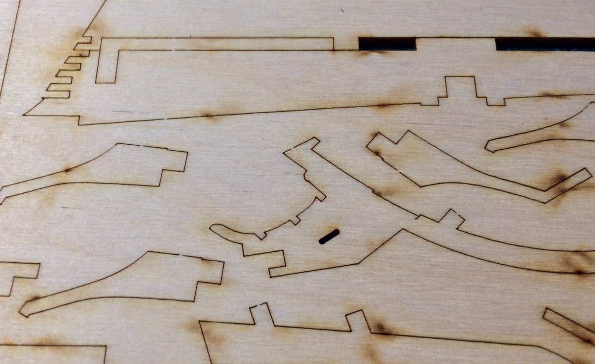
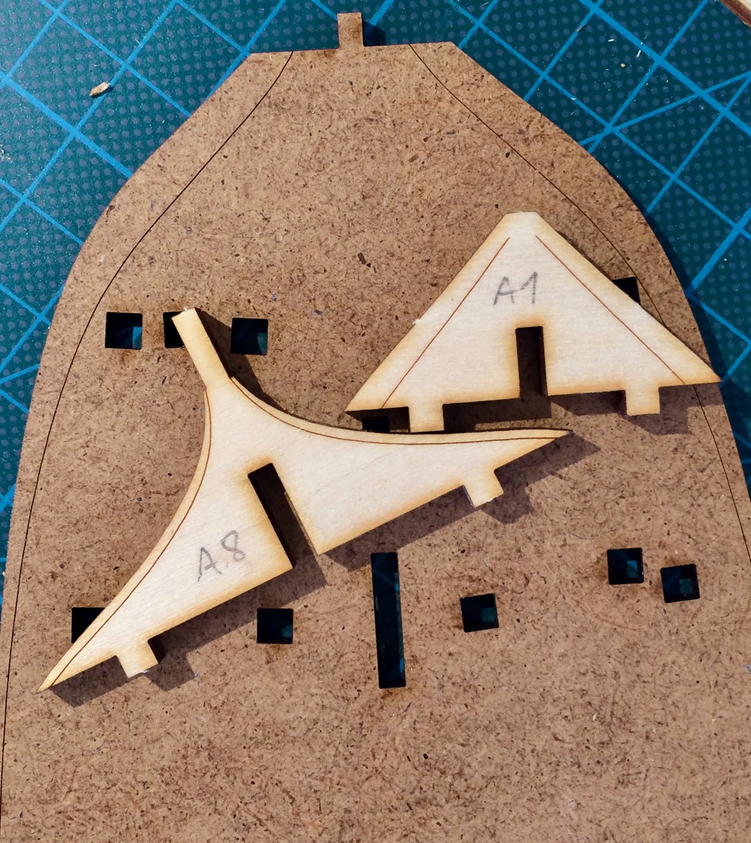
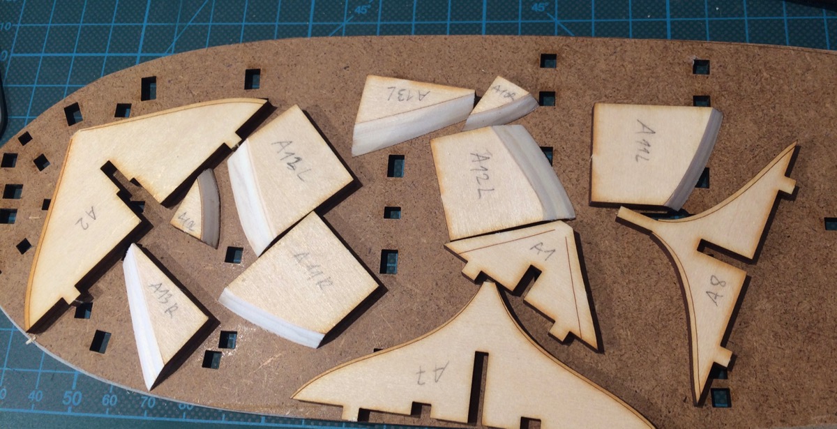
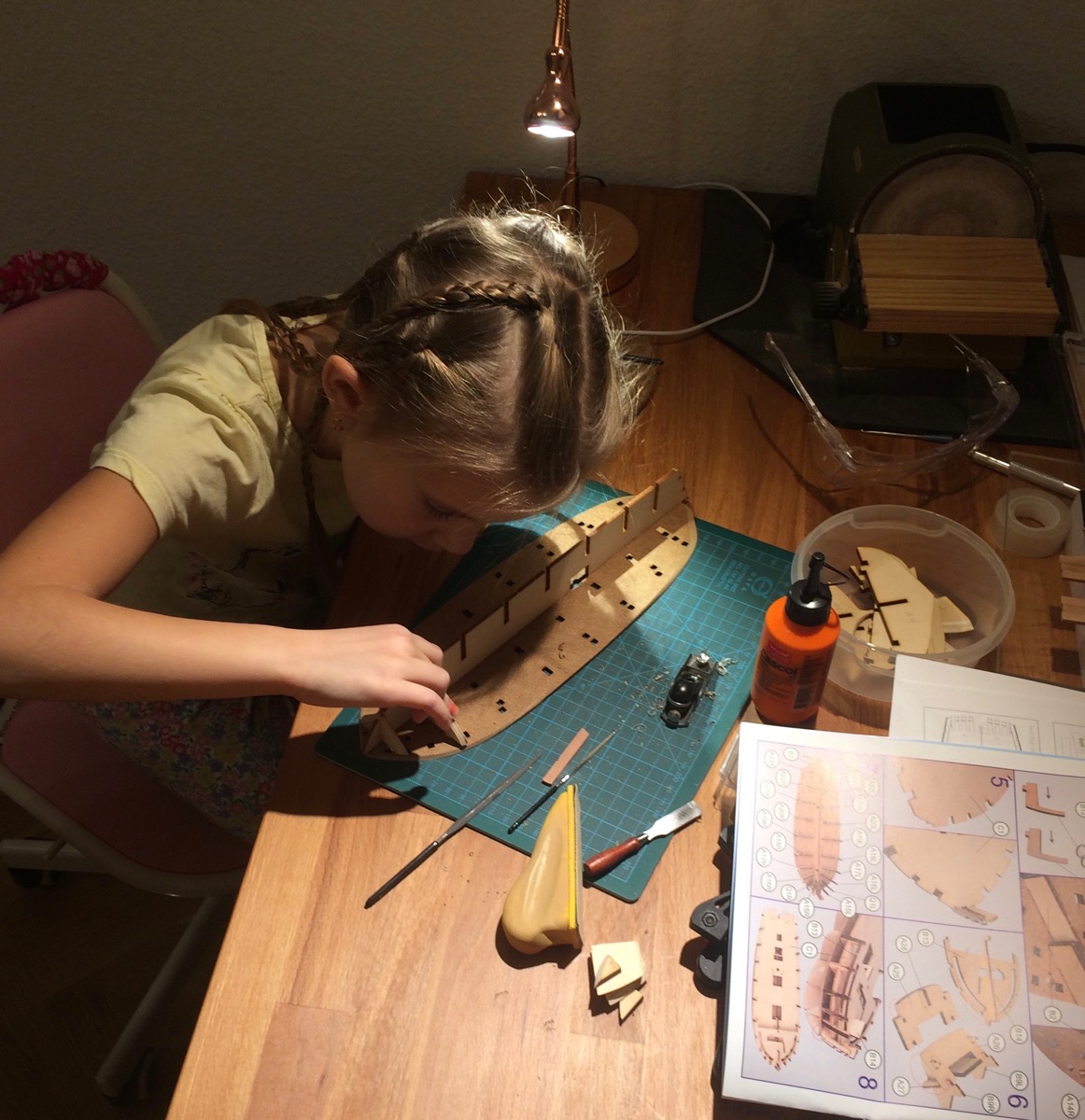
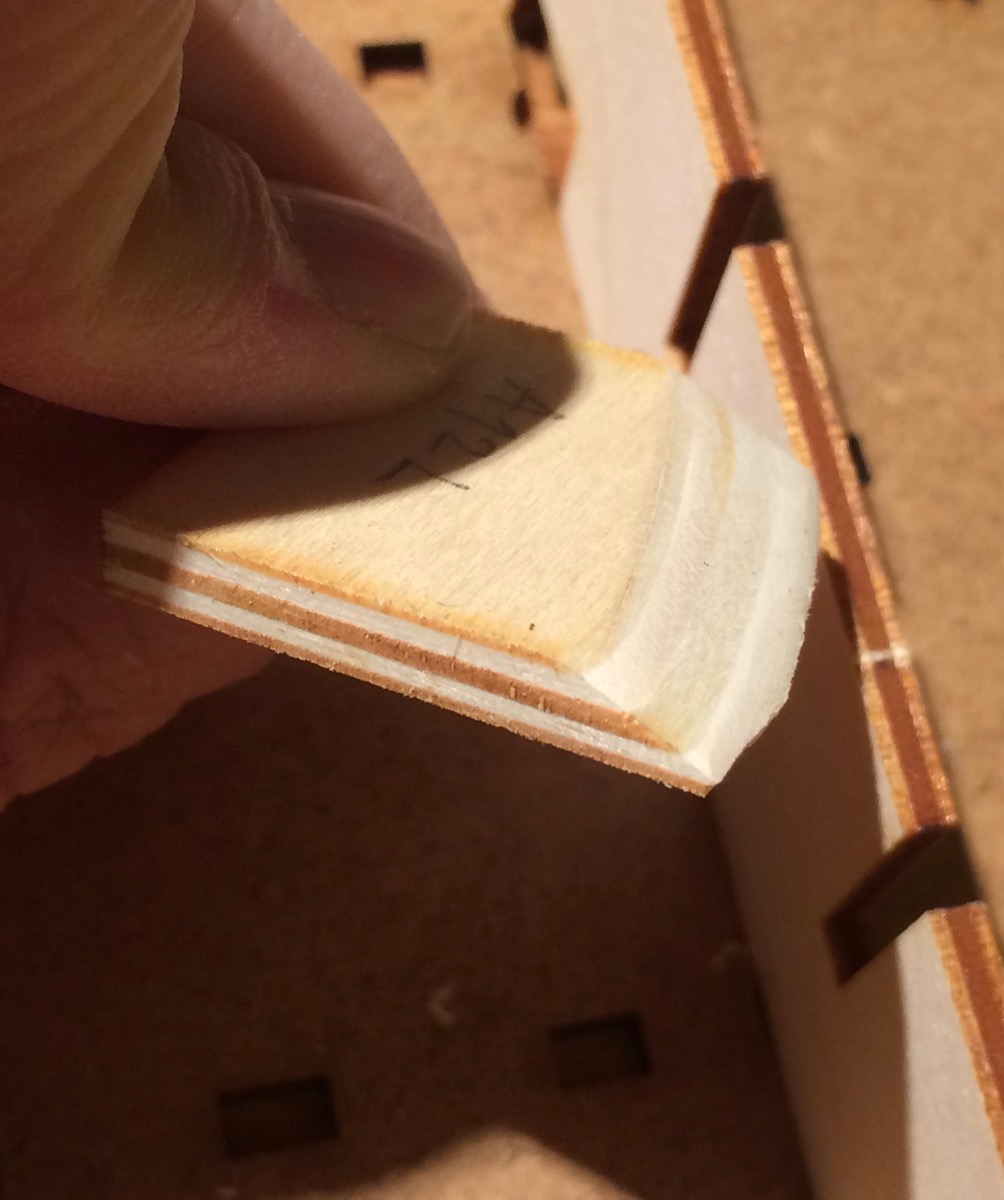
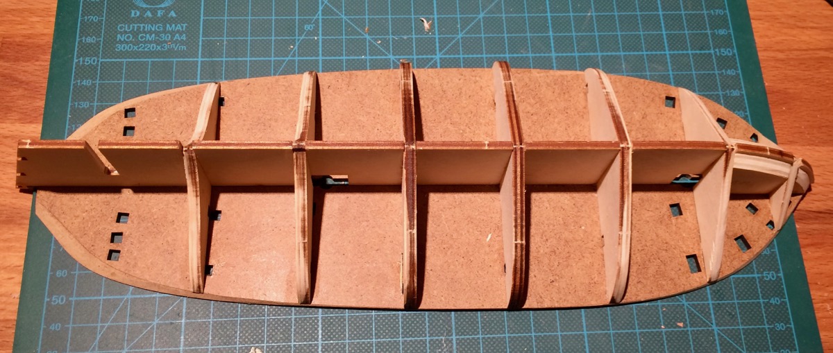
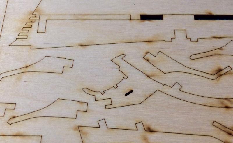
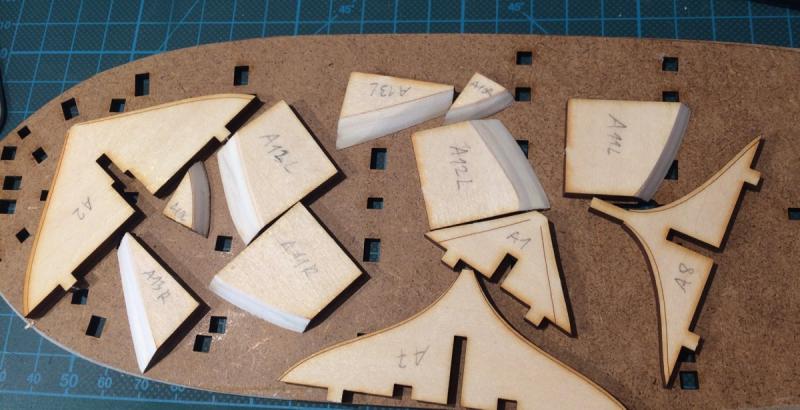
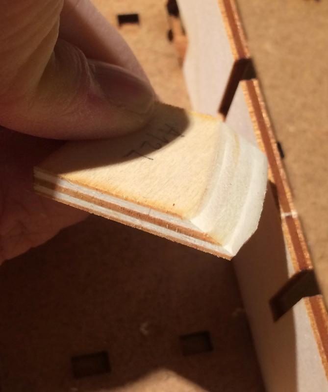
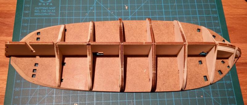
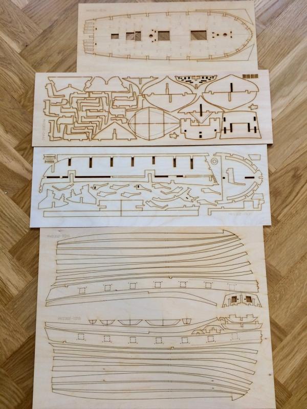
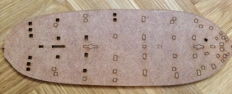
Really impressed with the kit quality! The laser cutting is super accurate, the kerf is minimal: All bevels are pre-marked, so you just follow the lines: The ply is good, very uniform, no defects, middle layers are not falling apart: Super impressive for the $95 kit. It is the quality you would expect from the $400-$500 range. Frames are inserted into clear slots in the base board, that ensure perfect alignment. Notches in the frames and keel are a bit too tight, so all notches and all parts require some filing to fit. That was a bit unexpected, and too tedious for my daughter (so far), so I spend some time filing.. Meh, boring task But there is a steady progress End result of the first two modelling sessions: The "building board" is, apparently, a permanent part of the hull (lower deck), the upper parts would be installed on top of it. Interesting idea!


-
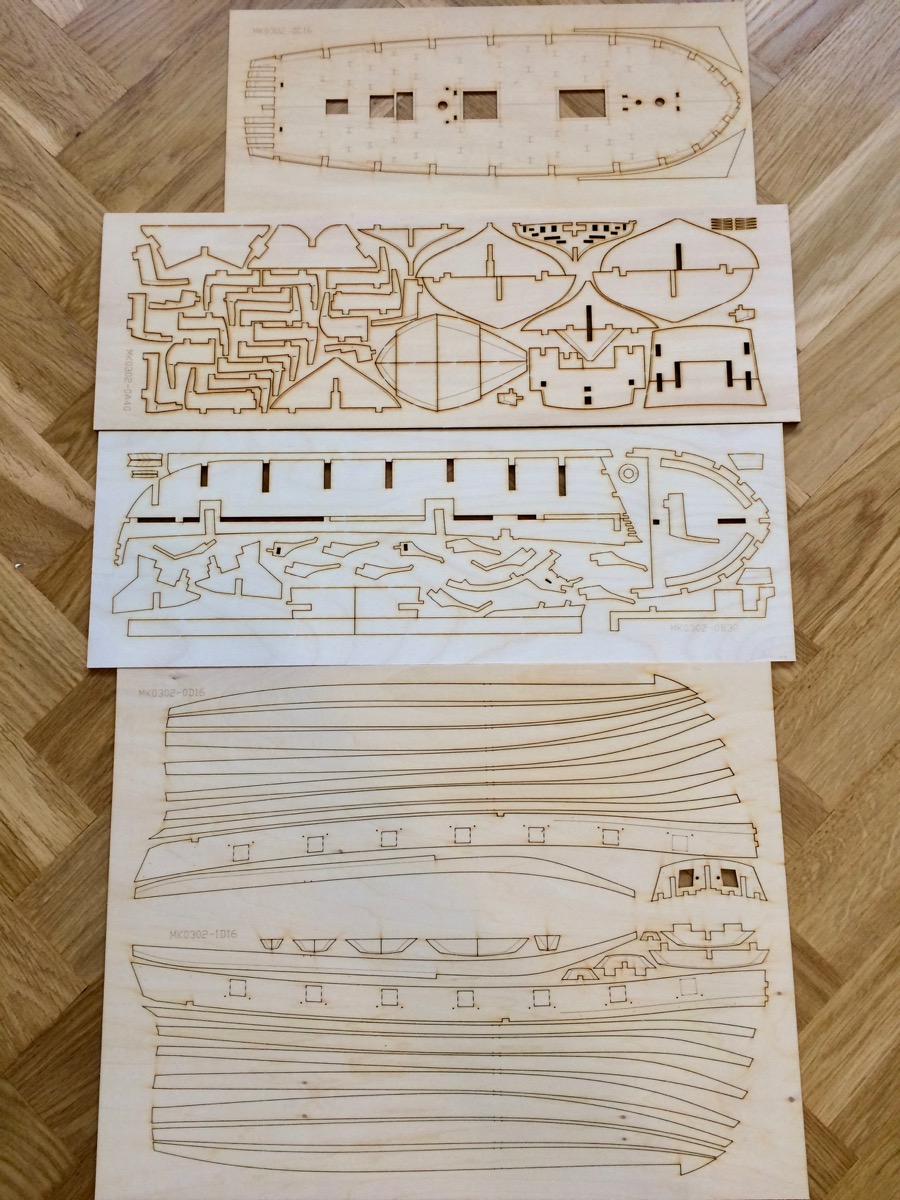
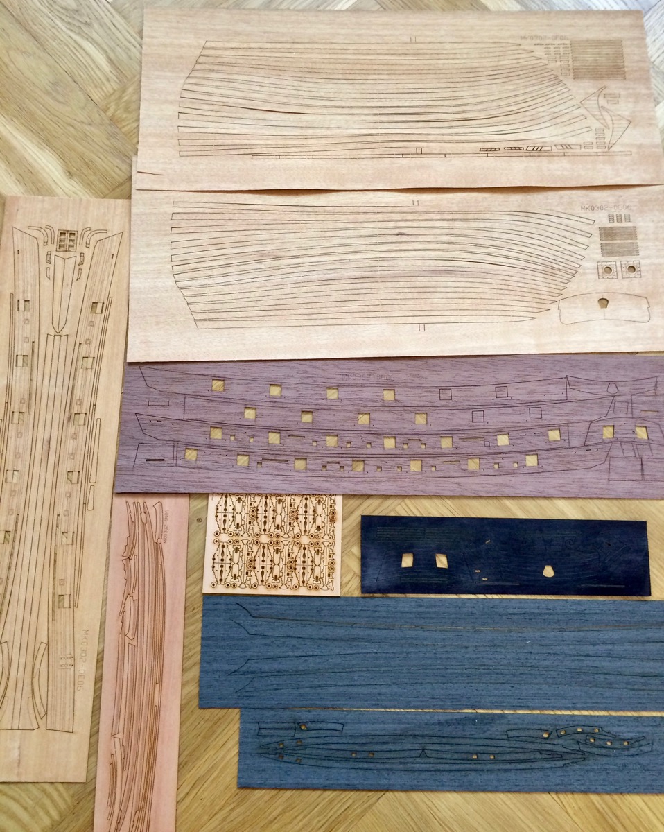
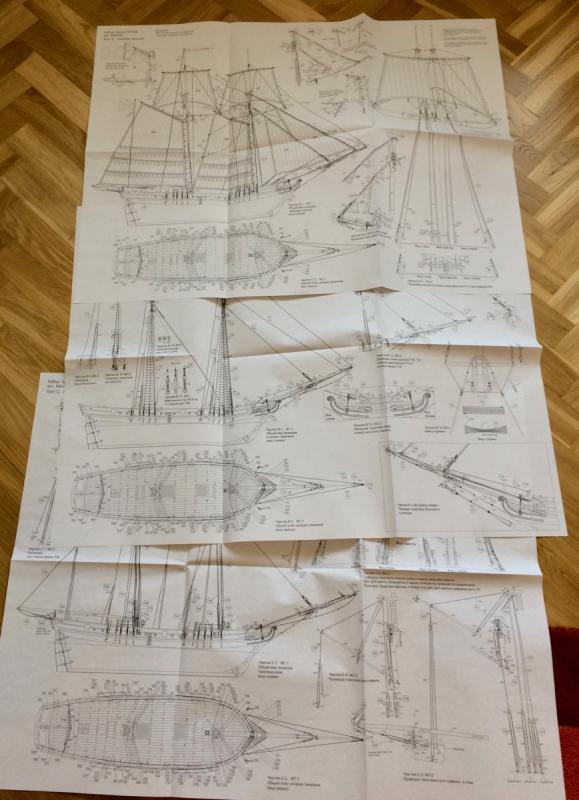
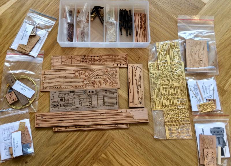
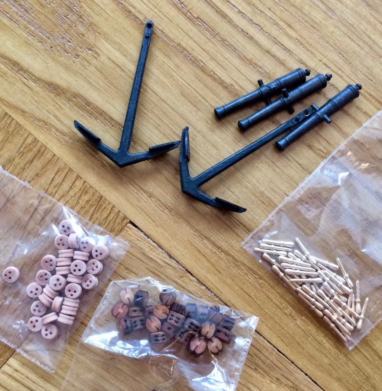
The kit: Super detailed plans: Fine parts: Castings: Laser cut parts: Laser cut finish level of planking and transom and other parts: Building jig:

-
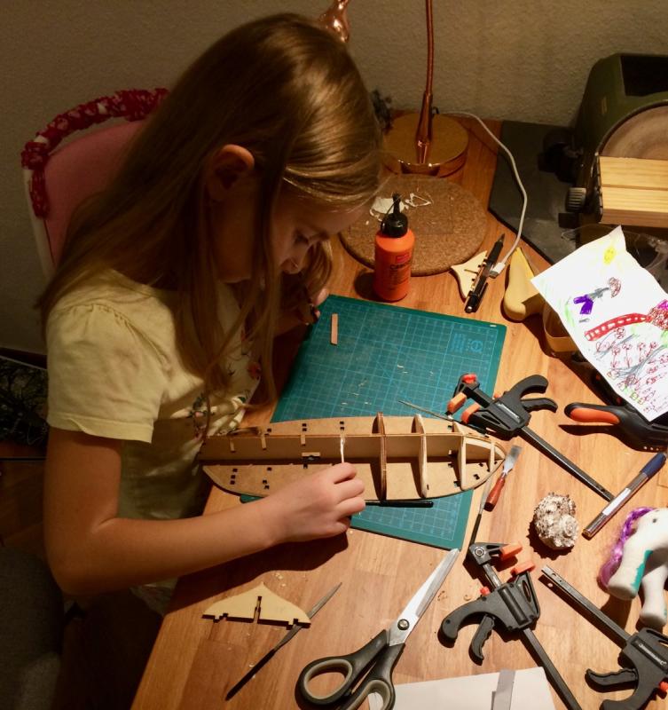
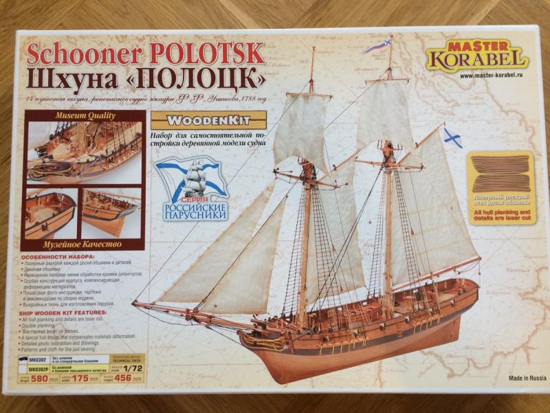
I am going to build this kit with my daughter. She was really insisting on building her own wooden ship, like daddy's. Seems to even be ready that it will take a year. Will see, will see, she seems to be really interested The kit is a 1777 schooner in 1:72 scale made by russian manufacturer Master Korabel (translated as "Master Shipwright"). Laser cut planking, nice wood, seems to be very well thought through! Includes few PE sheets, very nice castings (anchors and cannons), all fittings have a good quality. The laser cutting is top notch and plywood is high quality as well. Best part - the price is $95! Despite having english text on the box, all instructions are in russian. But maybe photo manual would be enough? Here is the link to the manual, it answers most of questions about this kit construction: http://forum.master-korabel.com/mk0302f.pdf Some build logs for the ones who are curious: http://forum.modelsworld.ru/topic13151.html http://serikoffshipmodels.com/forum/6-576-1 Got a few questions "where to buy the kit". My friend bought it in Russia and gave it to me, it is a cheapest option. I also found it on ebay, the seller has a 100% rating and looks like a producer of the kit. So maybe buying it directly from the producer via ebay is better. ebay.co.uk: http://www.ebay.co.uk/itm/mk0302p-Schooner-Polotsk-Wooden-Kit-wood-ship-1-72-model-master-korabel-/112015347120 ebay.com: http://www.ebay.com/itm/mk0302p-Schooner-Polotsk-Wooden-Kit-wood-ship-1-72-model-master-korabel-/112015347120 It is a "plus" version, so a bit more expensive. The kit I bought is a regular one - no boat and the blocks are simpler. The main goal is to enjoy the process together, learn the handcraft and generally have fun. In the end, I would be super proud of her if she will have enough stamina to finish the hull and plank it. That would be quite an achievement for 6 years old. I will try to show that kit in details, please pardon for the build quality - I am letting her to do as much as possible, not focusing too much on quality and accuracy. Step by step
-
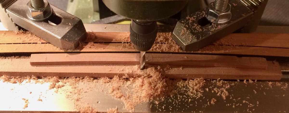
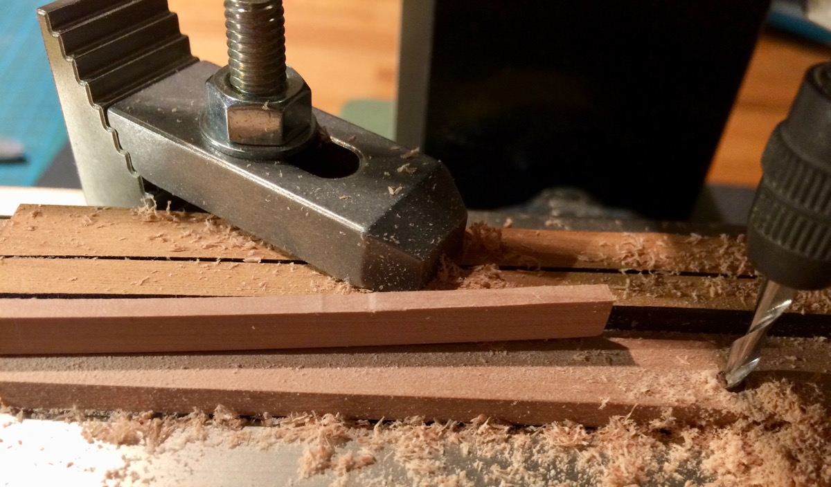
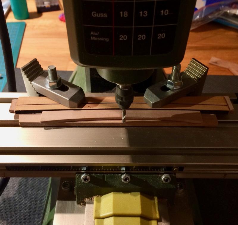
Experimenting with different ways to make a smooth arc-shaped curves, like for deck beams. Right now I need it for the transom, but the methods are the same, and should be used later for beams. Luckily I have a "template" of a proper curve - laser cut beams from the timbering set. Clamped that template to the mill, shaped the outside curve on a disk sander, and the inside curve - by slowly feeding the wood against the mill cut. Shallow passes.. It sort of works, but the main problem is making sure the wood is sliding along the template without twisting. Right now I do it with the fingers, one finger to the left of the cutter, one to the right of the cutter. Does not work very good - the chance of mistake or a wrong move is quite high, and the risk of injury is high. I got some nicks and dents: Nicks could be removed by sanding later on, but that kills the idea of precision milling. So I need some sort of tension that will allow to slide the wood against the template. Or maybe I just use the wrong approach. Will try a method described in TFFM (also on a mill, but the template shape is different). Would appreciate some advices!


- 969 replies
-
- 8
-
-
- hahn
- oliver cromwell
- (and 1 more)
-
Great idea with the "glue pockets"!
-
La Santisima Trinidad 1769 by Liberto - 1805
Mike Y replied to Liberto's topic in - Build logs for subjects built 1751 - 1800
Incredible accuracy and precision! Everything is so clearly marked up... Will use it is a reference, a good reminder that precise model requires careful measurements, markups and reference lines. Planking lines are soo smooth! I can go on and on and on please keep the pictures coming! -
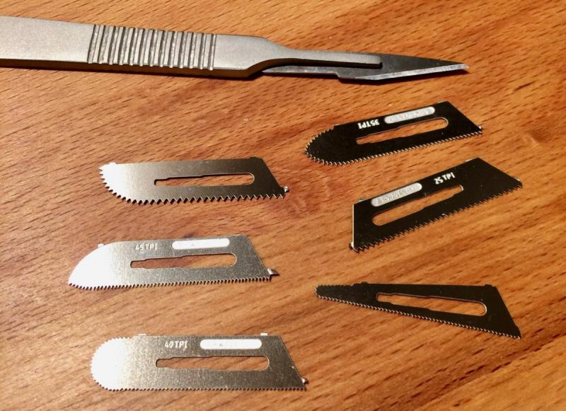
Carl, you can try googling "model craft saw set", plenty of shops in Europe that have it. Even amazon: https://www.amazon.co.uk/Modelcraft-1-Piece-Precision-Saw-Set/dp/B001JJXE9A/ref=pd_bxgy_201_img_2?_encoding=UTF8&psc=1&refRID=0MN1DH0GSEF1Q8CSJK38 They are compatible with stabdard scalpel handle.
- 969 replies
-
- 2
-
-
- hahn
- oliver cromwell
- (and 1 more)
-
Druxey, thanks! It is sold under a brand of a swedish company Model Craft AB. Unclear what is the original manufacturer... I quickly googled that you can find that in US, for example, here: http://www.modelcrafttoolsusa.com/saws-sawblades/862-replacement-saws-for-pkn0008-k.html http://www.modelcrafttoolsusa.com/saws-sawblades/864-replacement-saws-for-pkn0009-k.html
- 969 replies
-
- 3
-
-
- hahn
- oliver cromwell
- (and 1 more)
-
HMS Naiad 1797 by albert - FINISHED - 1/48
Mike Y replied to albert's topic in - Build logs for subjects built 1751 - 1800
Super! Every time you update the log, I want to write that - but need to stop myself to avoid polluting it too much Your build quality (and speed) is hard to match! -
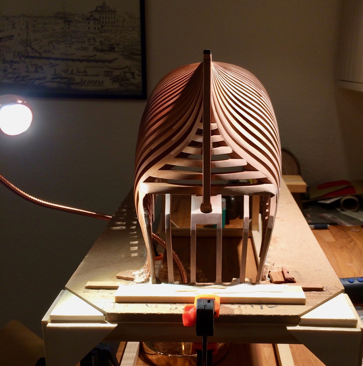
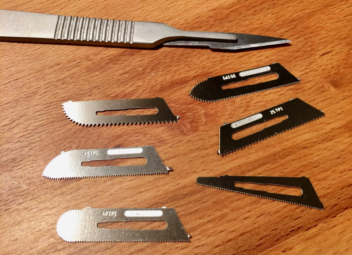
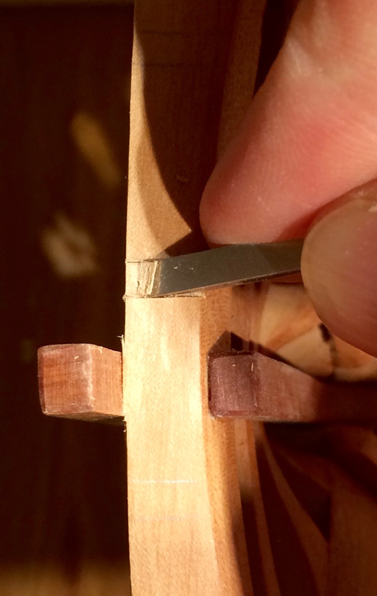
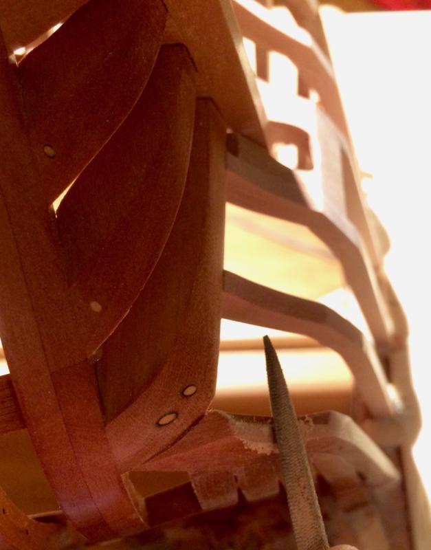
Progress is very slow, spent just an hour in the workshop Installed remaining counter timbers. Transom is quite skewed, so impossible to achieve a proper symmetry - but I hope I will hide most of it when planking one side of it. The goal is to align windows on planked side with the counter timbers on the unplanked one. Now fairing the timbers, the outermost counter timbers had a wrong angle. File is good enough for it: Btw, found a very nice scalper saw blades in the local hobby shop, was positively surprised! They could be found by "model craft saw set" query, and exist in two types.

- 969 replies
-
- 32
-
-
- hahn
- oliver cromwell
- (and 1 more)
-
Love reading your log, feels like building it myself these "inline" comments on the photos are very handy!
- 132 replies
-
- 4
-
-
- triton cross-section
- cross-section
- (and 1 more)
-
Galley Washington by Mike40 - 1:48 - POF
Mike Y replied to Mike40's topic in - Build logs for subjects built 1751 - 1800
Please do not use that scary looking hammer on your model! It looks good -
Erik, sorry to hear it, hope you will overcome it and will be back on your feet soon! Best wishes
-
Proxxon Micro Planer DH40 - owner feedback??
Mike Y replied to rtropp's topic in Modeling tools and Workshop Equipment
Mauricio, sorry, I haven't changed or adjusted the blades in my planer yet, they are good enough so far. -
Should look great in wood!
-
Finally, a Le Fleuron update! The middle photo looks the best
- 728 replies
-
- 4
-
-
- le fleuron
- 64 gun
- (and 1 more)
-
It sort of kills the purpose then? There are lots of cheaper thickness sanders in the market. Dust collection would be a big issue, this planer is designed to produce shavings and do not have any dust protection or collection. It will just clog all mechanisms including feeder belts and gears. Not even mentioning the amount of dust in the room. I never needed much sanding after using that planer, it produces a nice smooth finish, few passes with scraper or xacto blade over the ready-made part - and the finish is perfect.
-
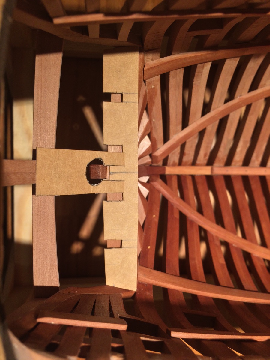
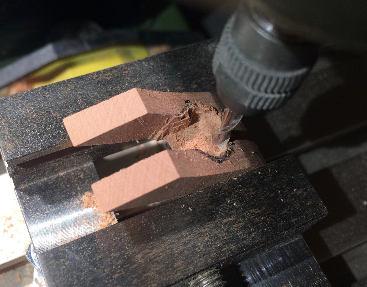
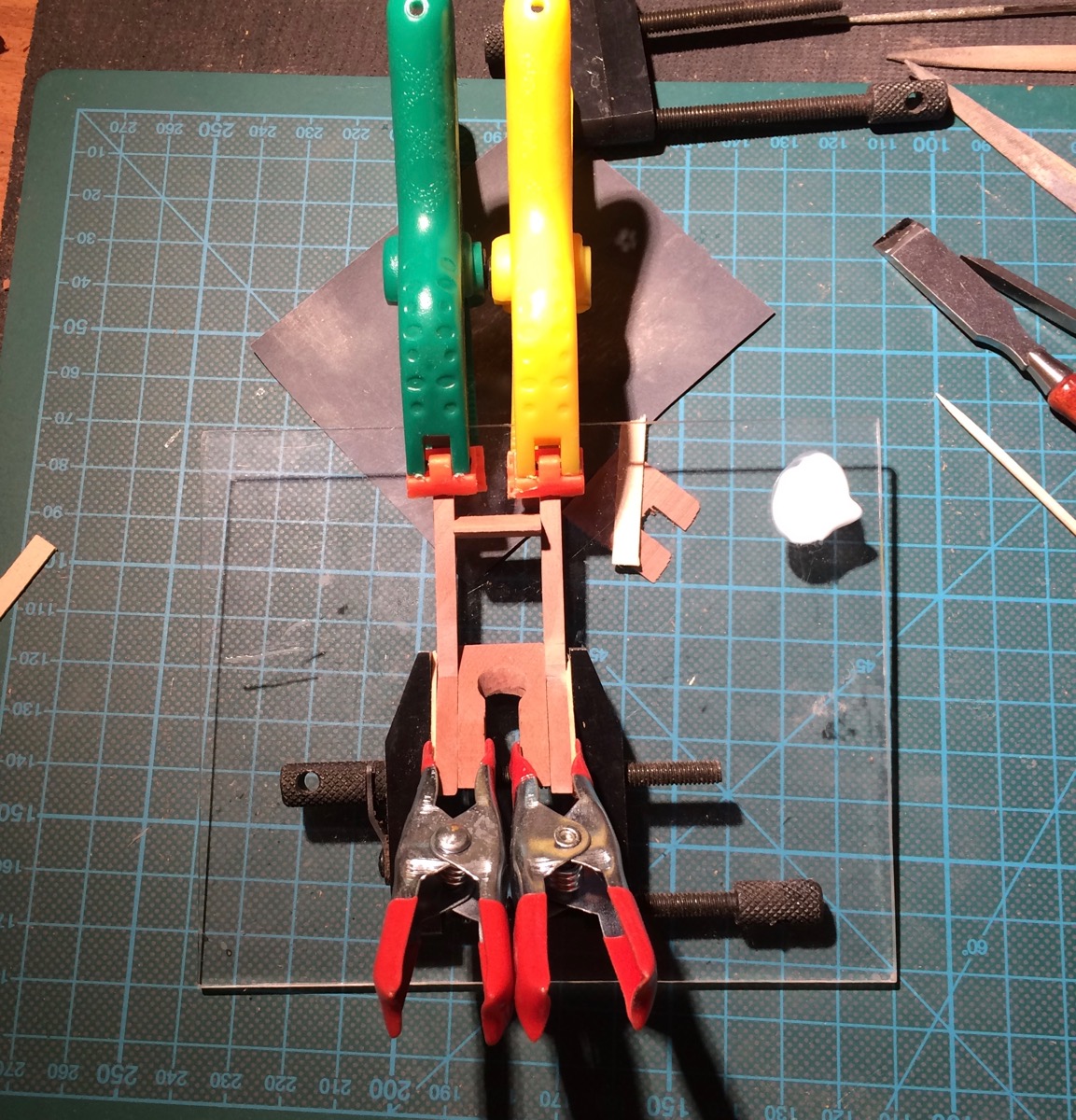
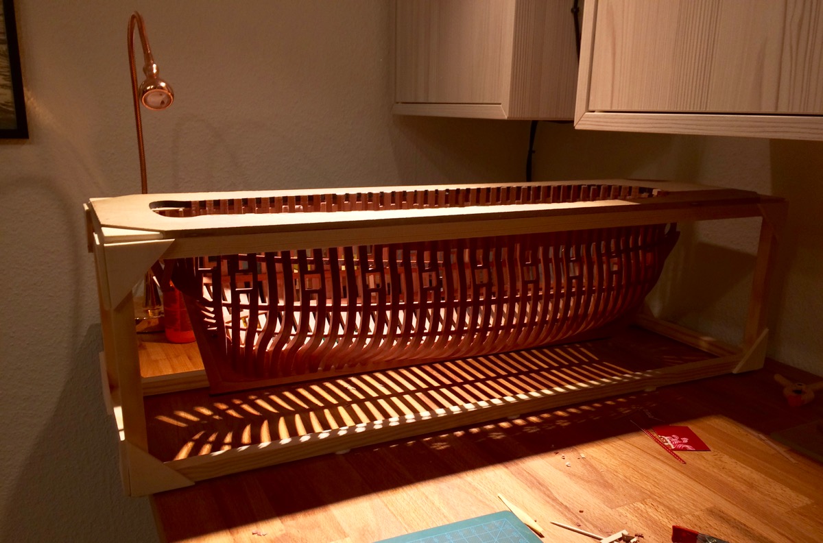
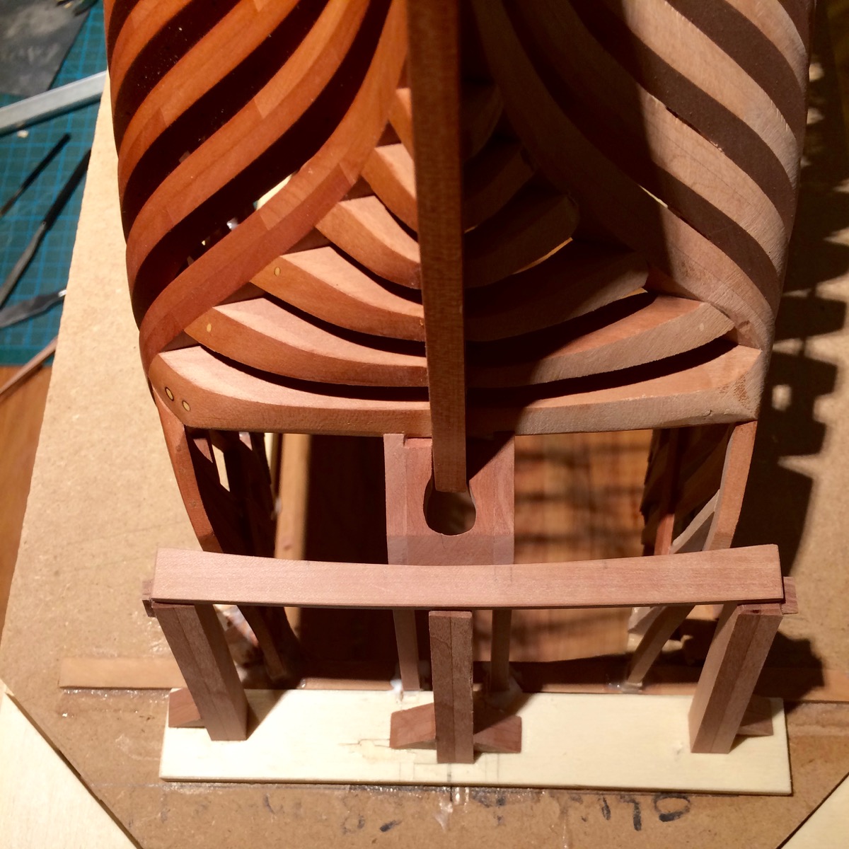
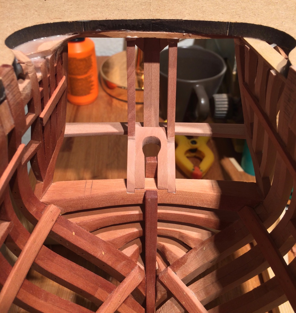
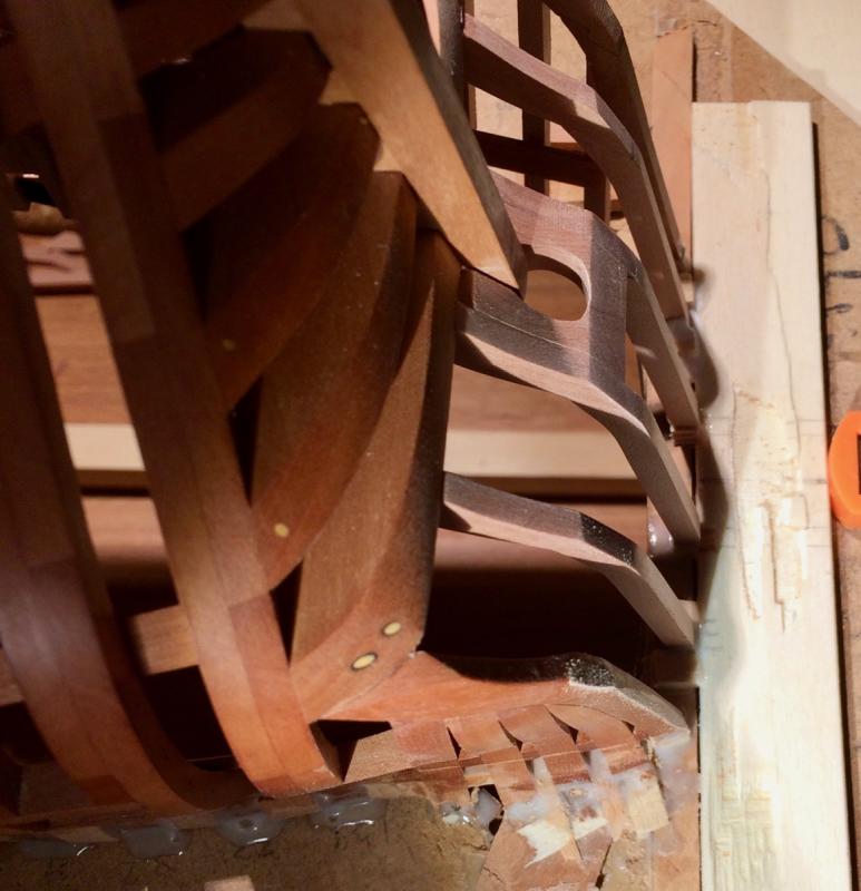
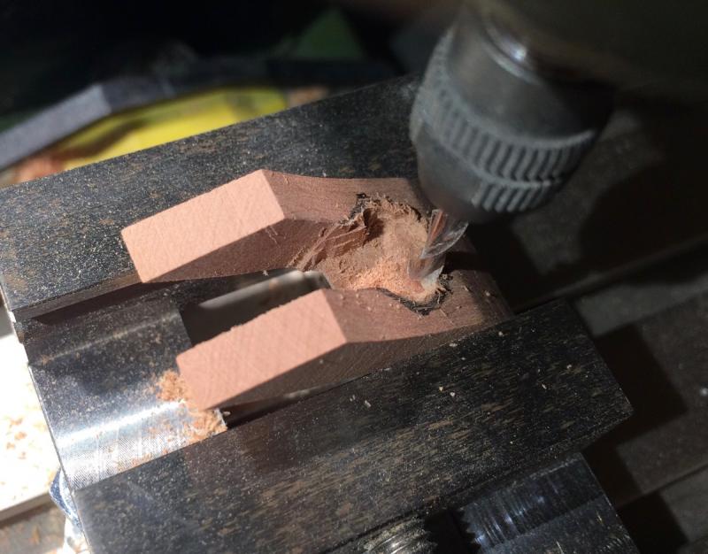
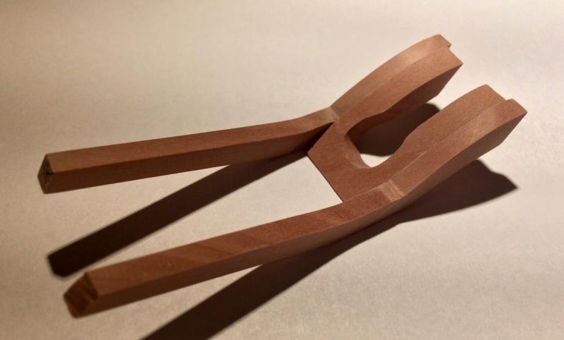
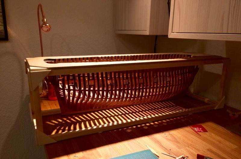
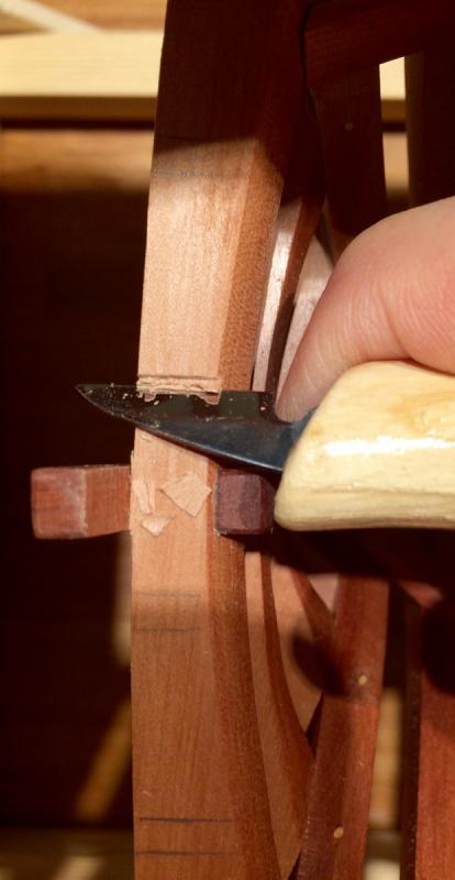
Thanks Glenn, Cap'n Poison and Mike! Worked on those pesky counter timbers and helm port. Lots of meaurements, doubts and re-measurments involved! Step 1: carefullty mark counter timbers location. I should admit that my transom is not very symmetrical - few mm here and there. Nothing really big, and one should have a really sharp eye to see it in person, but the ruler does not lie Will measure better next time! So a lot of time was spent trying to find a right balance to ensure symmetry in the scope of a single side. Asymmetric planking (one side planked, one side exposed) will help as well. Cardboard templates ftw! Careful viewer will note a mistake #1 here - helm port is for the rudder, not for the sternpost. Luckily I spotted it next morning. Lesson learned - do not do marking and measuring of such difficult areas at night, being tired. It is a recipe for disaster. Helm port piece was cut on a bandsaw and the weirdly angled hole was first cut in the mill, and then fine shaped with files: Then the whole assembly glued together: Mistake #2 - the assembly is too weak, there is only one thin "bridge" keeping two sides together. Combine it with the grain following the stress line, plus counter timbers providing leverage - expected result - it snapped into two parts right in the middle. Ouch! Glued them back together, and it not very visible. It snapped before final sanding, so it was possible to use lots of glue and sand away any traces of it from the surface. Hope it will not become apparent after applying the finish. Assembly ready for installation: Mistake #3 - I have not pre-cut notches in the wing transom, doing it in place. Hull sides make it impossible to properly use chisel, the angle is too square. So used a tiny one plus knife: End result is so-so, I am not happy with the fit, there are small gaps in the glue joints, but I did not to spend few weeks doing that part again... It would not be too visible below quarterdeck. I hope! At least the counter timbers ended up square and in line with already installed timbers. Phew! Obligatory "light and shade" shot:


- 969 replies
-
- 38
-
-
- hahn
- oliver cromwell
- (and 1 more)
-
What is your preferred work height?
Mike Y replied to Nirvana's topic in Modeling tools and Workshop Equipment
They exist in two versions - 120cm and 160cm. But you can buy a frame only and attach any table top to it, which gives you a better flexibility in terms of size. The frame is quite stable and done well, so bigger table top will not be a problem. -
What is your preferred work height?
Mike Y replied to Nirvana's topic in Modeling tools and Workshop Equipment
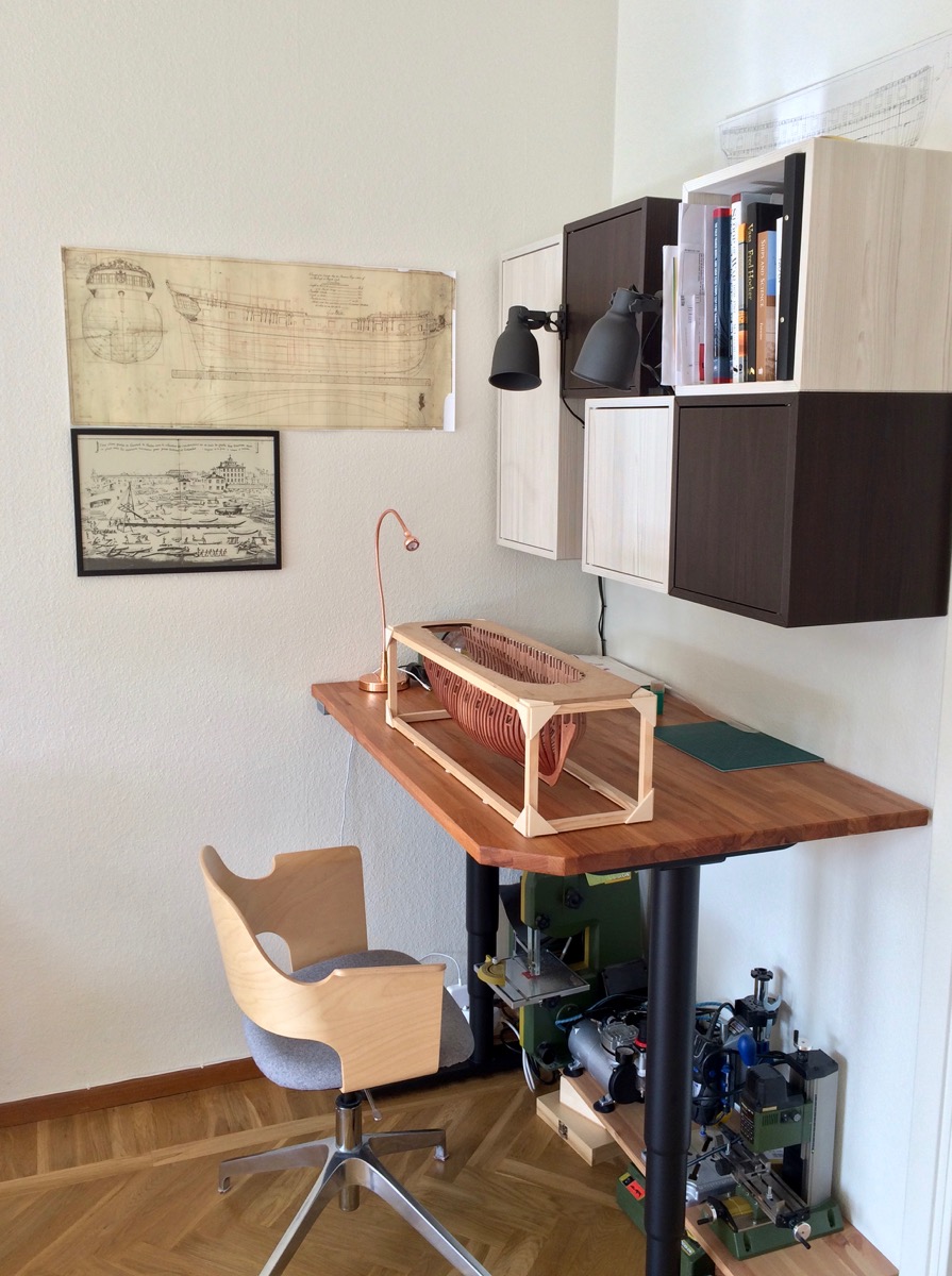
I switched to the adjustable one (just $400 in ikea, http://www.ikea.com/us/en/catalog/products/00263218/)and am really happy ever since. No more head or neck pain, bending in a weird pose, etc. I move it a lot when working, depending on the type of the operation. It is heavy and stable. That is how it looks. Max height is 1cm below the drawers level.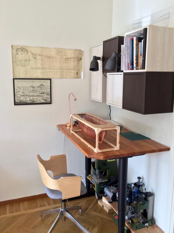
-
Galley Washington by Mike40 - 1:48 - POF
Mike Y replied to Mike40's topic in - Build logs for subjects built 1751 - 1800
Looks neat! Hope the wood is not too soft, but at least fairing should be easy! Will grab a char, if you do not mind