Mike Y
-
Posts
1,557 -
Joined
-
Last visited
Content Type
Profiles
Forums
Gallery
Events
Everything posted by Mike Y
-
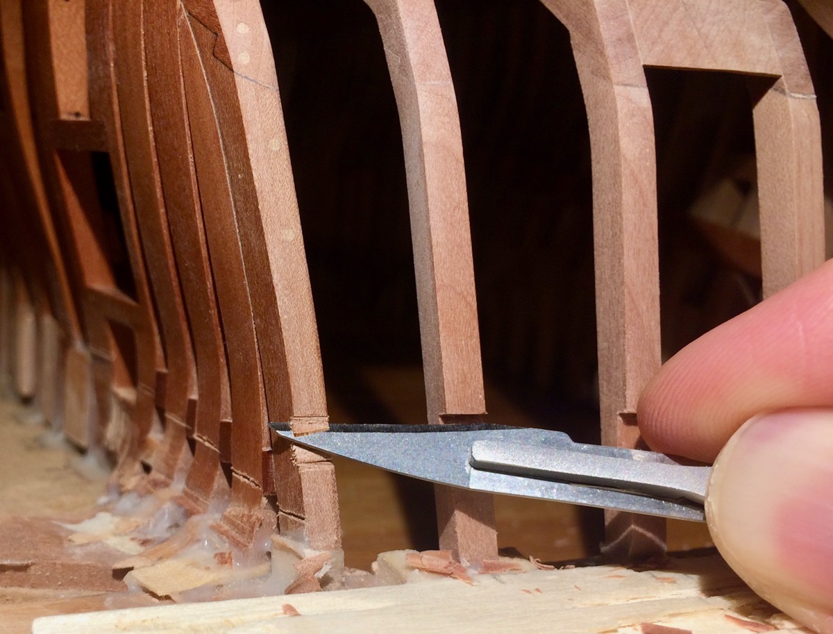
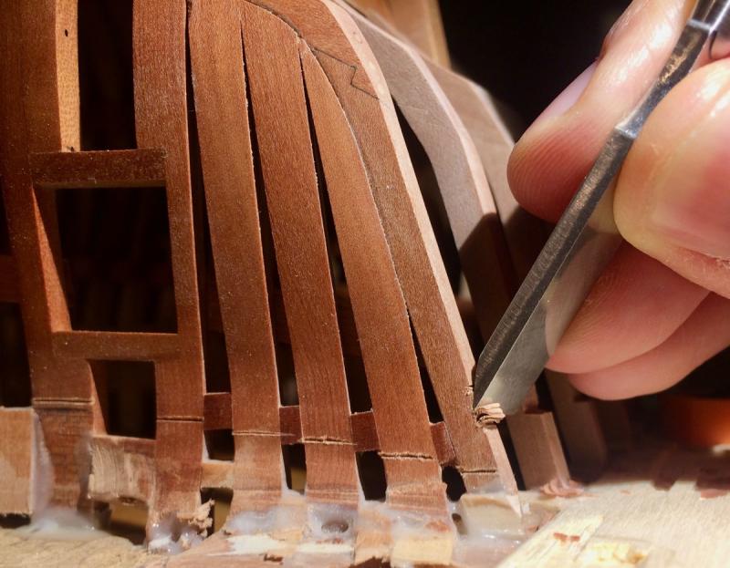
 Finally got an hour to work on a model - light up some candles, prepare tea, nice music, relax.. Still fine-tuning that pesky notches. Sorry for receptiveness of the photos, but want to share because this turned out to be a tricky task. I should have made the transom assembly in advance, probably... Broke the scalpel handle to make it easier to bend it - that is the only way I found to make this cut:
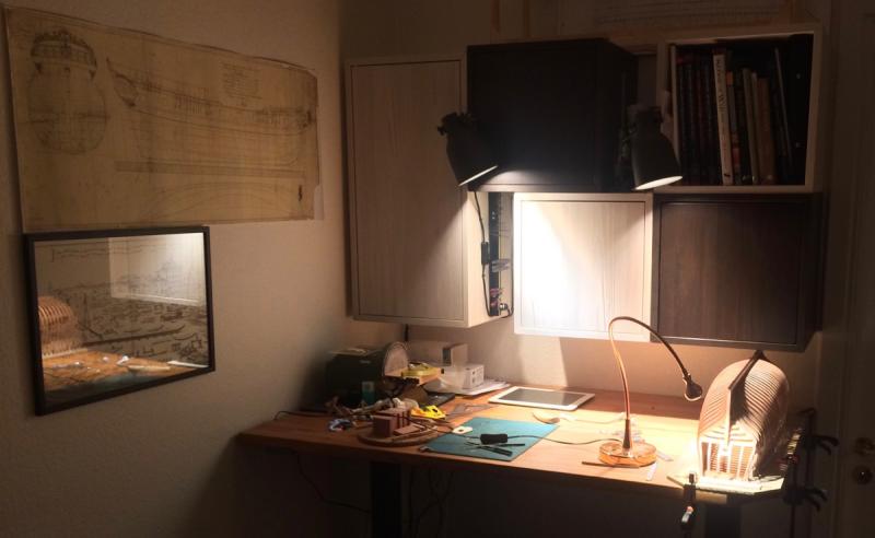

- 969 replies
-
- 23
-

-
- hahn
- oliver cromwell
- (and 1 more)
-
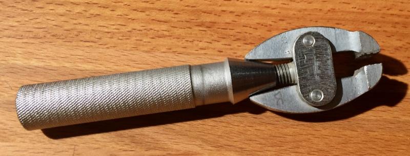
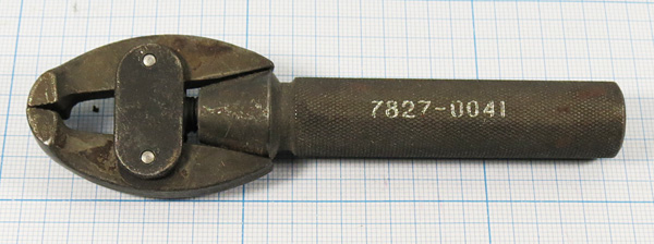
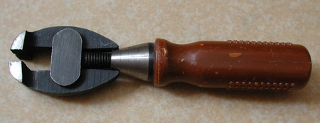
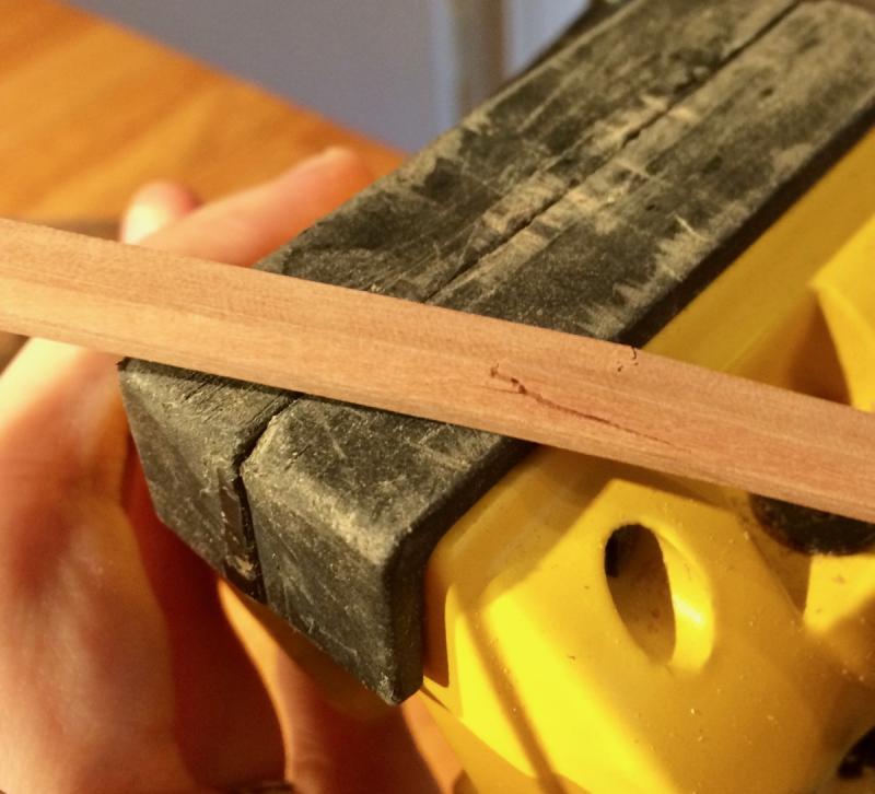
Hi Michael, Here is a close-up: For the context: my grandfather was a radio research engineer in USSR. He was working on the technologies similar to first cellular networks. He was a total radio geek (in a good way), and had an engineering mindset applied to any part of life. His apartment was full of various electronic elements, catalogues and reference books. Pity that he is not with us anymore, he would really appreciate my hobby and line of work, so much to share... The vice does not have any name or logo on it, and looks really well made (especially by soviet standards). There is a first letter of his last name hand-engraved on it - to prevent his co-workers from "borrowing" that hand vice. That hints that this tool was not widely available, and was valuable enough to be protected this way (nobody will "borrow" a tool that everybody has). Doubt that the tool is made by him personally (he was definitely not into making tools, metal working or woodworking), but it could easily be something custom-made. Any sort of factory-produced tool in USSR had an identification number and a price tag stamped on it. This one has nothing similar, so probably not produced on a large scale. Here are similar hand vices of a factory-produced kind (not mine, pictures from the internet). Note a different handle and an identification number: Old tools are an interesting angle to learn about history, work culture, industry of the time...
- 969 replies
-
- 7
-
-
- hahn
- oliver cromwell
- (and 1 more)
-
Pandora by marsalv - FINISHED - 1:52
Mike Y replied to marsalv's topic in - Build logs for subjects built 1751 - 1800
Somehow I missed this log previously... Had a lot of a great catch-up today! The quality and precision is excellent, planking is great, everything is a pleasure to read.. Thank you, this log is a pure joy -
Looks very interesting! Please keep the pictures coming!
-
HMS Alert 1777 by Jaekon Lee - 1/64
Mike Y replied to Jaekon Lee's topic in - Build logs for subjects built 1751 - 1800
Dear Lee, Hope you are ok, and looking forward for new updates! This build made me seriously think about small scale for the next model, there is a certain charm in it! Your model is a real piece of art, and it looks close to completion! -
The new gear is super neat! Love the joints and their shapes. It is a piece of a pretty precision engineering!
- 525 replies
-
- 3
-
-
- anchor hoy
- hoy
- (and 1 more)
-
Toni, thanks for the idea! Will try that as well. Wonder how artists are not going insane from all that variety of paints, brushes and application techniques Hi John,See http://modelshipworld.com/index.php/topic/7297-oliver-cromwell-by-mike-y-148-1777-pof-hahn-style/page-25#entry454181 and https://www.amazon.co.uk/Modelcraft-1-Piece-Precision-Saw-Set/dp/B001JJXE9A/ref=pd_bxgy_201_img_2?_encoding=UTF8&psc=1&refRID=0MN1DH0GSEF1Q8CSJK38 Or just google "modelcraft saw set", it is available in a number of shops. Note that there are two different sets - one with smaller saws, another with a bit larger saws.
- 969 replies
-
- 5
-
-
- hahn
- oliver cromwell
- (and 1 more)
-
That is another way to do it, but I am worried about sanding through the thin layer of ebony. It is always better to have a big margin for fairing/sanding Plus it implies I still need to have ebony dust in my living room, which I would like to avoid...
- 969 replies
-
- 5
-
-
- hahn
- oliver cromwell
- (and 1 more)
-
Thanks everybody for the nice words! She was quite pleased Hope the enthusiasm from her side will remain. It is an good opportunity for her to learn that some things are not done overnight...
-
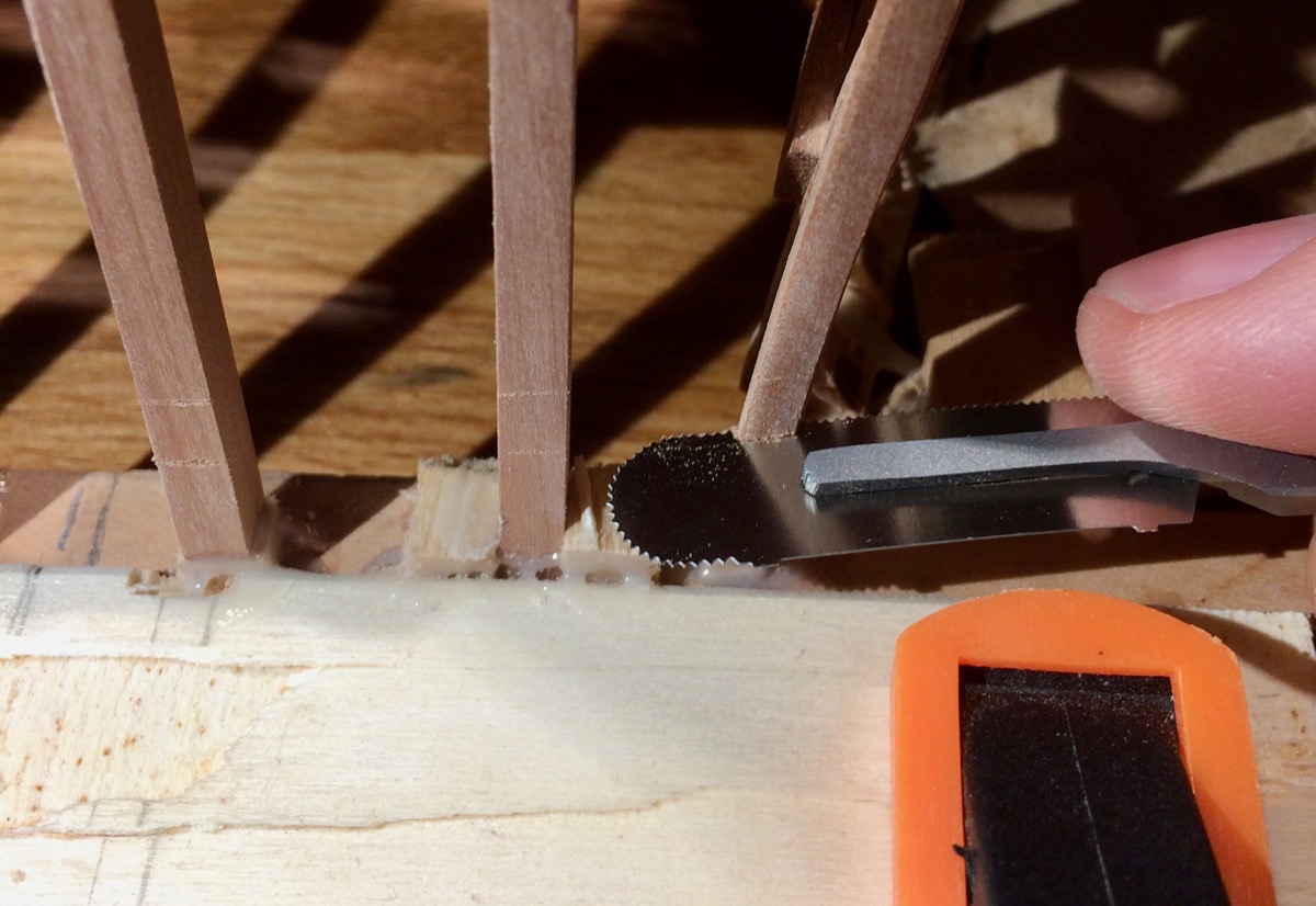
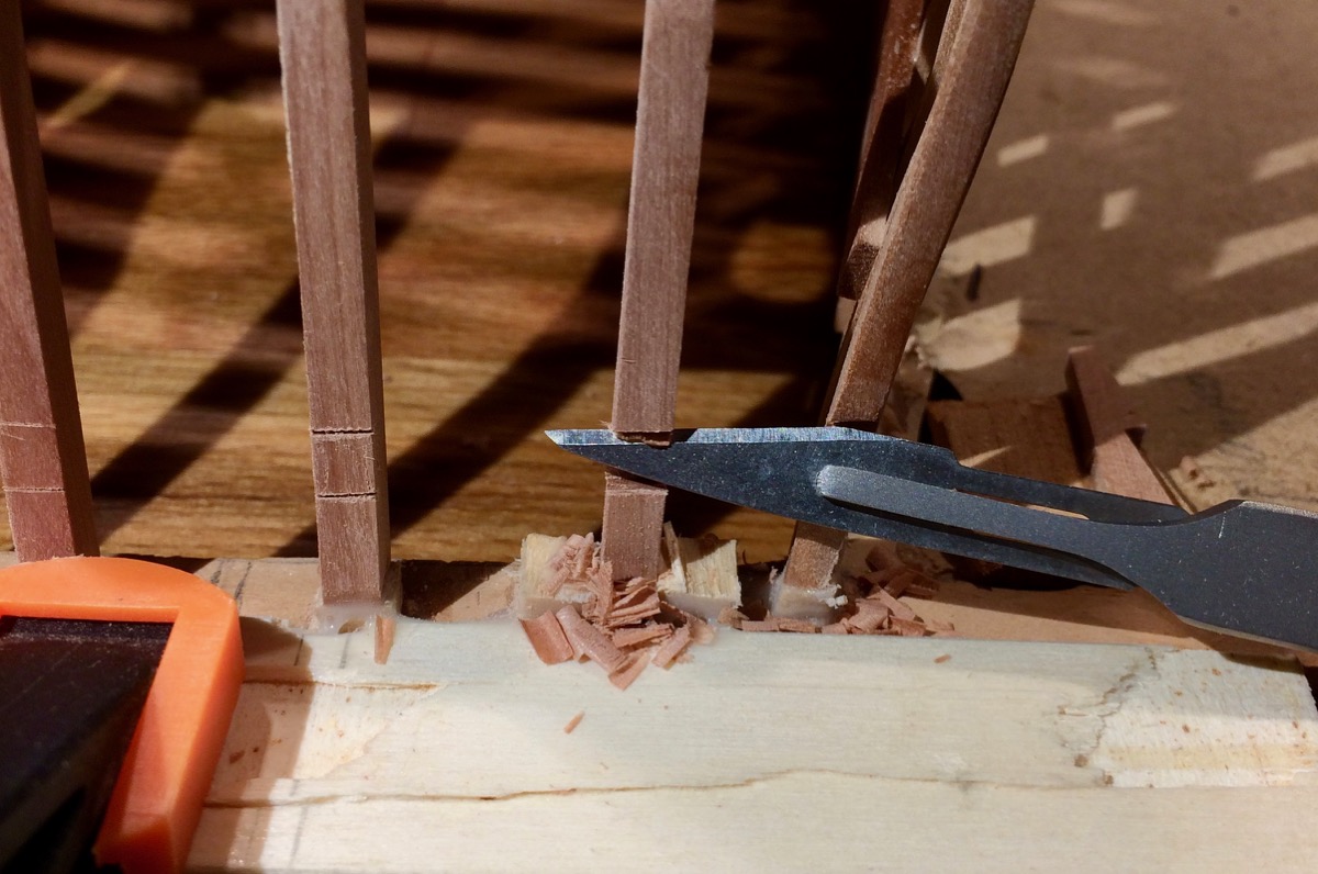
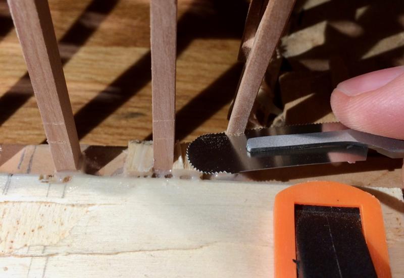
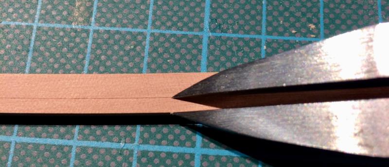
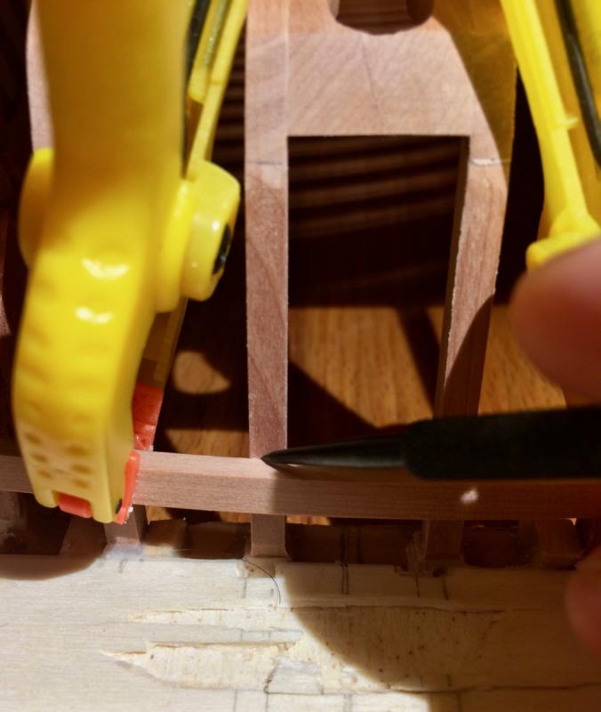
Making notches. New micro saws were handy to start them accurately without slippage: And scalpel is really handy to remove the wood further. Very little force required, hence a good control of the cut. They flex much more than xacto blades, which makes it convenient for such application. Super happy with them, thanks Gaetan for making me try scalpels!

- 969 replies
-
- 17
-
-
- hahn
- oliver cromwell
- (and 1 more)
-
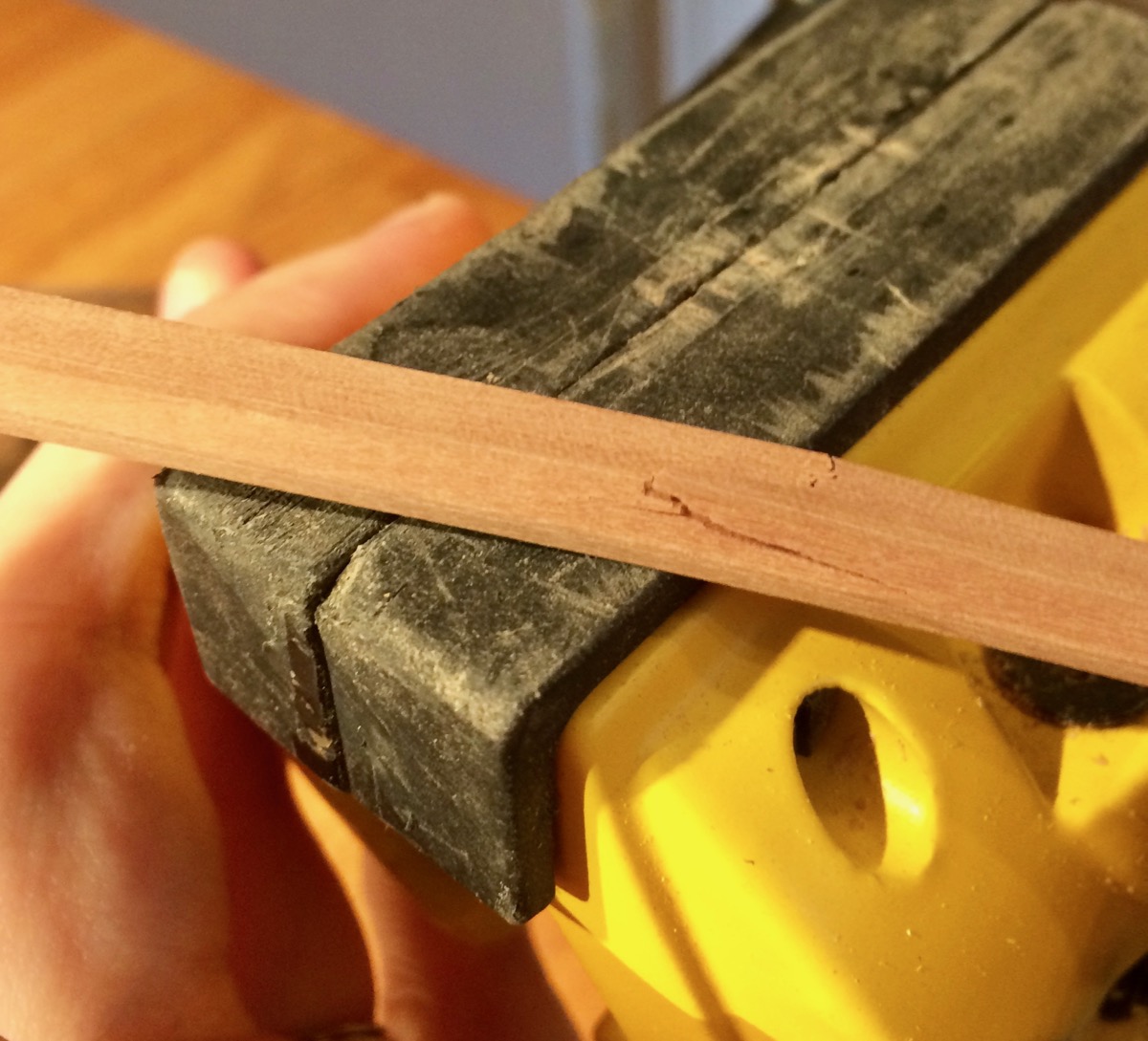
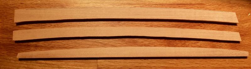
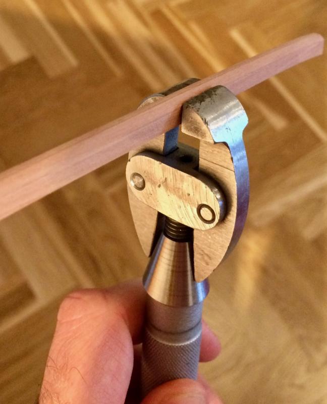
Finally got a few hours to work on the model Tried a better method of cutting the inner lines of the slightly curved pieces, using a mill. It is described in TFFM, and with a very slight improvements it works really well! The blanks are cut on the bandsaw, and outer curve is shaped on a disk sander: After milling - smooth inner curve, super consistent width, and no nicks! One of the timbers has a bevel, dividers are really handy to properly mark it up: Result: That timbers are curved in two dimensions, and another curve I made by dry-bending with heat. Finally used my granddad hand vice that I have no opportunity to use previously Seems like my hair dryer is too gentle and is not hot enough So two timbers cracked when I was gently bending them around a large cooking pot. Will try some cheap chinese hair dryer that does not care about your hair and can produce really hot air Or just go back to the steam/boiling method, it worked pretty well. Careful alignment and markup: Now need to cut the notches and make everything flush!

- 969 replies
-
- 16
-
-
- hahn
- oliver cromwell
- (and 1 more)
-
Thanks for sharing! I truly appreciate the advices from the experts! Yes, it is hard to control penetration, so I was planning on dyeing off-model only. Except wales, I want to sand/scrape them first to make sure they are even and smooth. Meaning I will need to dye a small part of the plank that fits the stem, and the rest would be dyed on model after fairing. All remaining planking would be done after wales, so no risk of dye sipping into the other planks. I want to use some finish to seal the surface - to avoid marring with fat fingers. But want to keep it matte. Danish oil is too shiny indeed, but tung looks good and matte enough. Poly would be too shiny. So water-based stain with two coats of tung oil looks really close to what I want, now I need to see how it changes over time. Will also try Holly and a shoe dye for comparison.
- 969 replies
-
- 6
-
-
- hahn
- oliver cromwell
- (and 1 more)
-
Carl: super, sent a PM! Lou: yes, followed Chris' log with an awe, but I was under impression that he used Fiebing's shoe dye... Will re-read again Druxey: to be honest, after reading Remco's blog, I am a bit worried about using the shoe dye. I know many used it without any problems, but his experience is a serious reason to avoid that dye... Or I am overthinking it? There are so many combinations of the wood + dye + finish, I may soon run out of test pieces!
- 969 replies
-
- 4
-
-
- hahn
- oliver cromwell
- (and 1 more)
-
Hmm! I was following the common sense that "it is better to use wood dye for wood, not the shoe dye". Probably I was wrong.. Will test the shoe dye as well! Although I am pretty happy with the look of the water-based wood dye. Soft, monotone, even, a little bit grainy, exactly what I need for wales. But might be too fluffy for small parts.
- 969 replies
-
- 4
-
-
- hahn
- oliver cromwell
- (and 1 more)
-
druxey, thanks for the advice! Will try it as well. Hope it would not be too far away from pear, because getting holly in Europe is reeeeally expensive (ordering in US + intercontinental shipping + import tax + customs fees). I bought a bit for boats (yes, like the one on your picture, dreaming of making something similar)
- 969 replies
-
- 3
-
-
- hahn
- oliver cromwell
- (and 1 more)
-
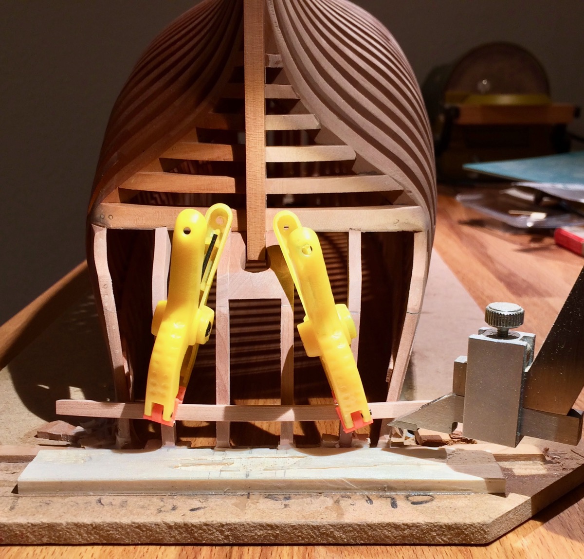
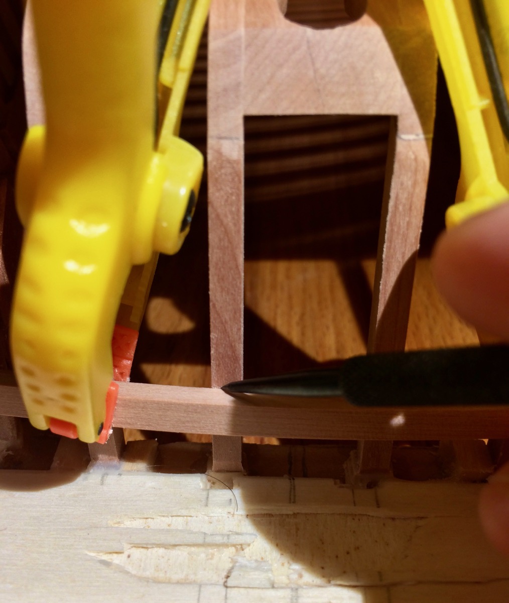
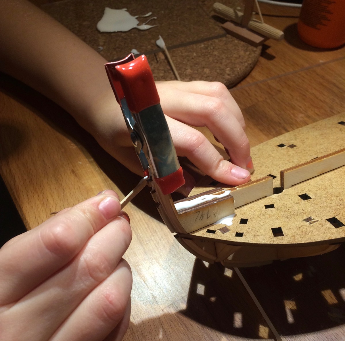
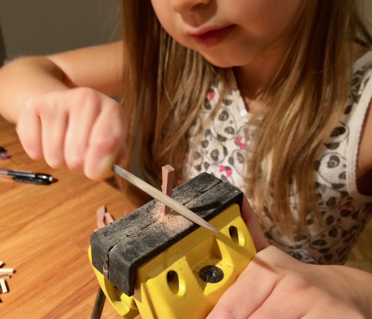
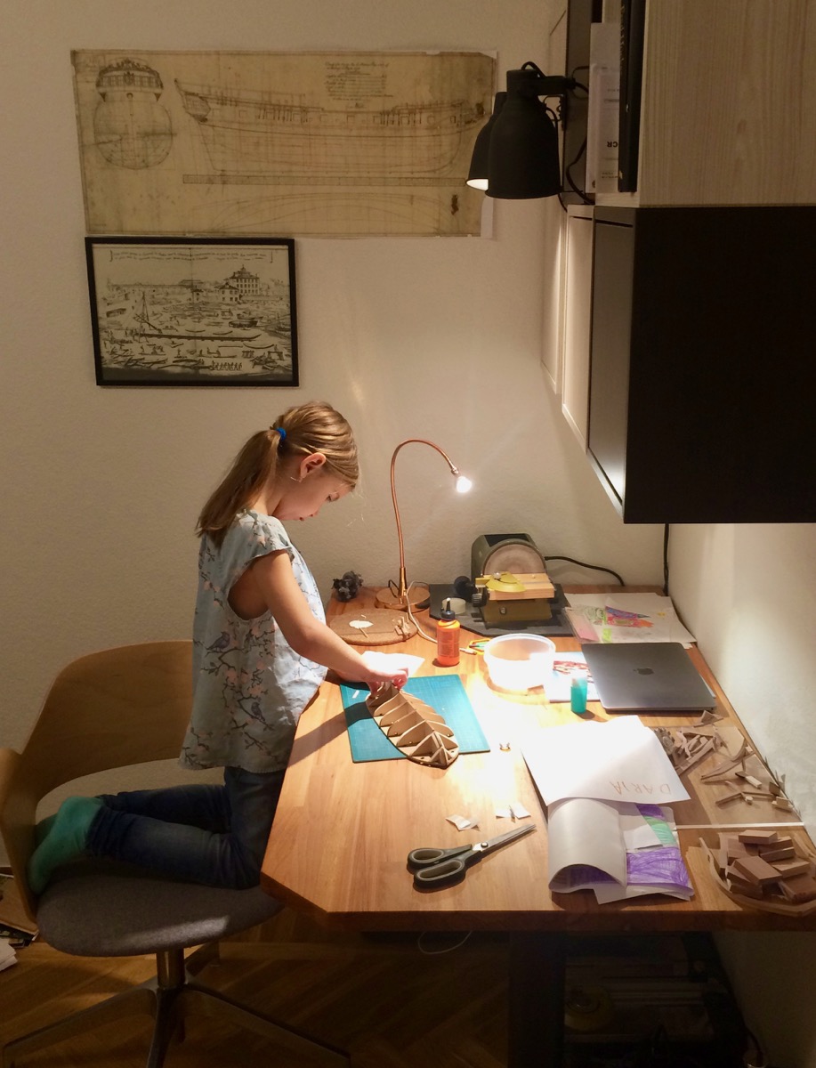
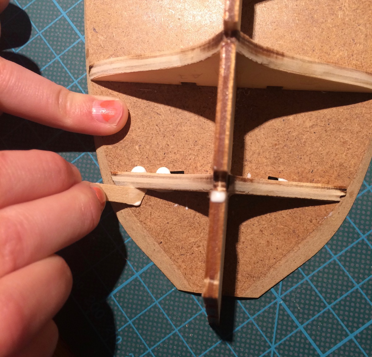
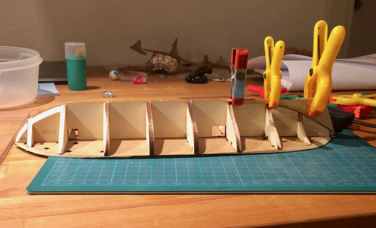
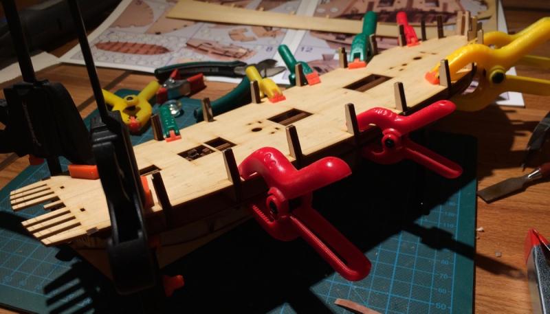
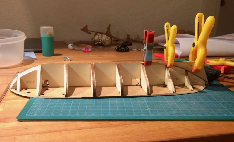
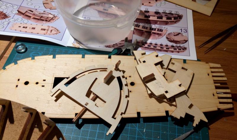
Thanks Karl! Yes, I am also quite surprised with her passion to building stuff, and trying to feed this passion by showing her different techniques, materials, doing it together, encouraging, etc. No matter what career path she will choose, an engineering mindset will never hurt! This time she also dictated her first post in the build log. I just translated it to english with minimal syntax corrections: I am building this ship with my dad. He helps me, but I build it myself. I am a Daughter Daria. We are making a ship body (hull). I am gluing the parts: This is the center of the ship, I insert the parts here: And remove an extra glue with a stick: We used clamps to help the glue stick parts together: I also made some wooden things with a file. These things are now inside the ship. Here we glued the deck. It was hard to fit all that parts at the same time! Our ship will be big! With a long masts and big sails. We will ship some things, food, paintings and curtains on it, as well as toys and doll stuff.


-
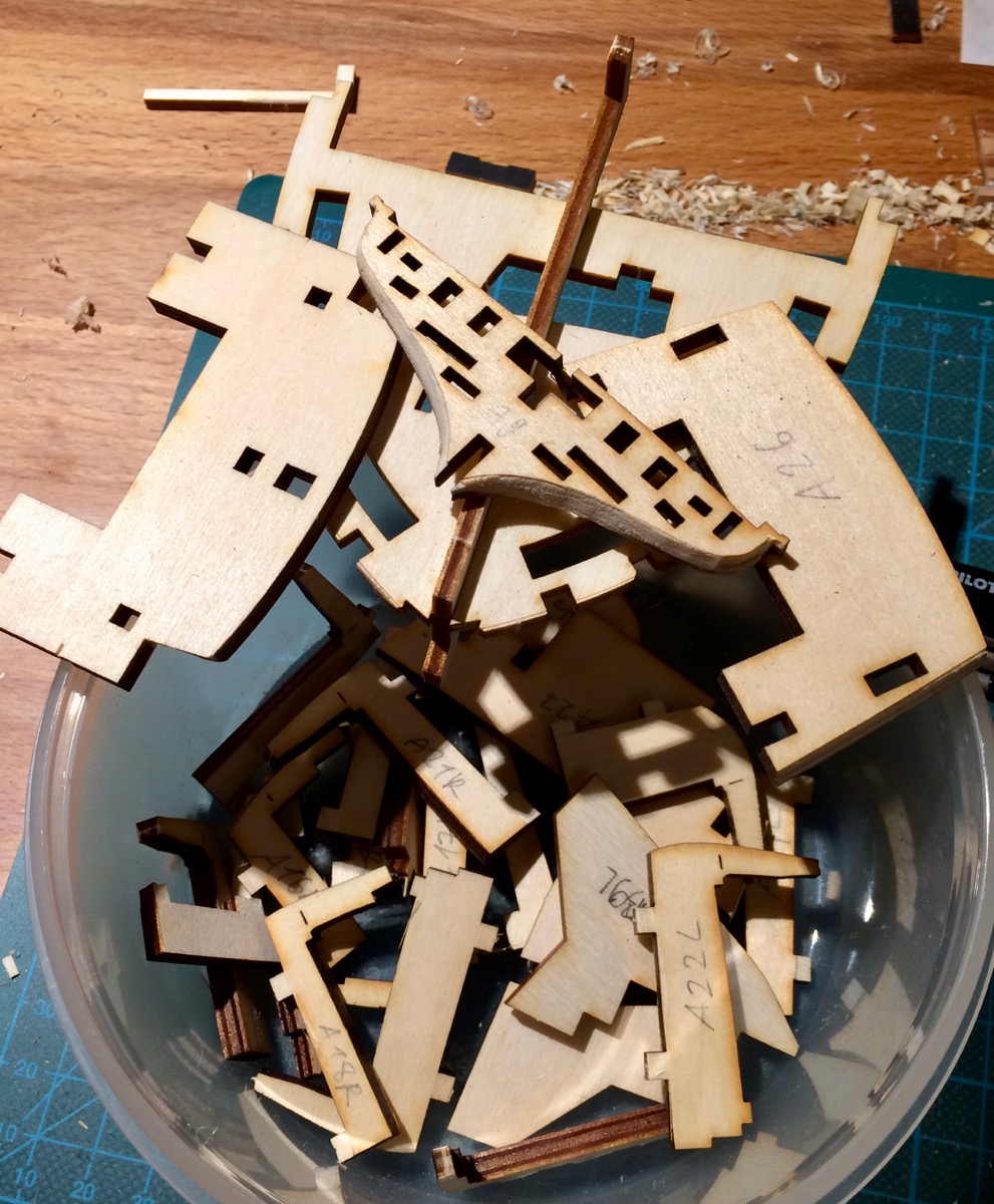
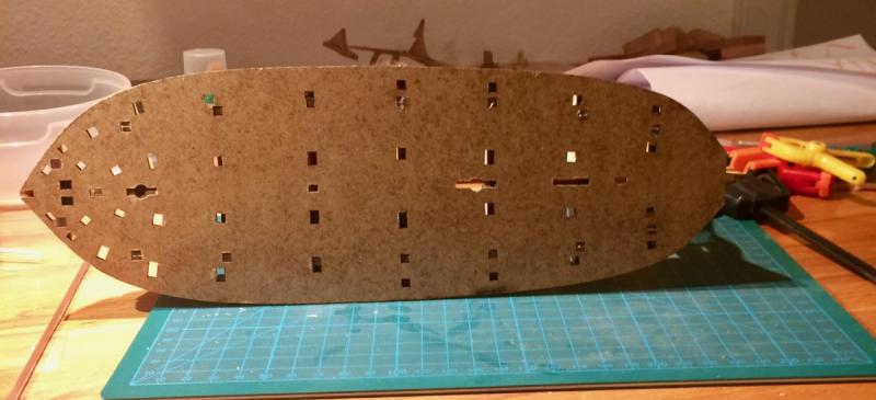
Proper photo update is coming soon, but in a meanwhile - a little bit about the kit. It sure has a lot of notches and parts connected by inserting them into that notches. The problem is that all that connections are too tight. Nothing could be inserted without filing it first. Using the brute force can lead to cracks and broken parts, and I hate doing it this way. Fine fitting connections + wood glue are better than brute force So before she can build the next step - I spend some time with a file, knife and chisel, making sure everything fits. Frankly, that is quite tedious and boring. As you can see, the kit has hell lot of notches! And every single one should be enlarged with a file.

-
Peter, thanks a lot for the suggestion, I truly appreciate it! I have some ebony as well (used it for the false keel), but would try to avoid it because of the nasty dust, its hardness and a massive cleaning required after any operation with ebony. (I do not have a workshop or a dust collection system). Looks like dyed pear is a good substitute...
- 969 replies
-
- 5
-
-
- hahn
- oliver cromwell
- (and 1 more)
-
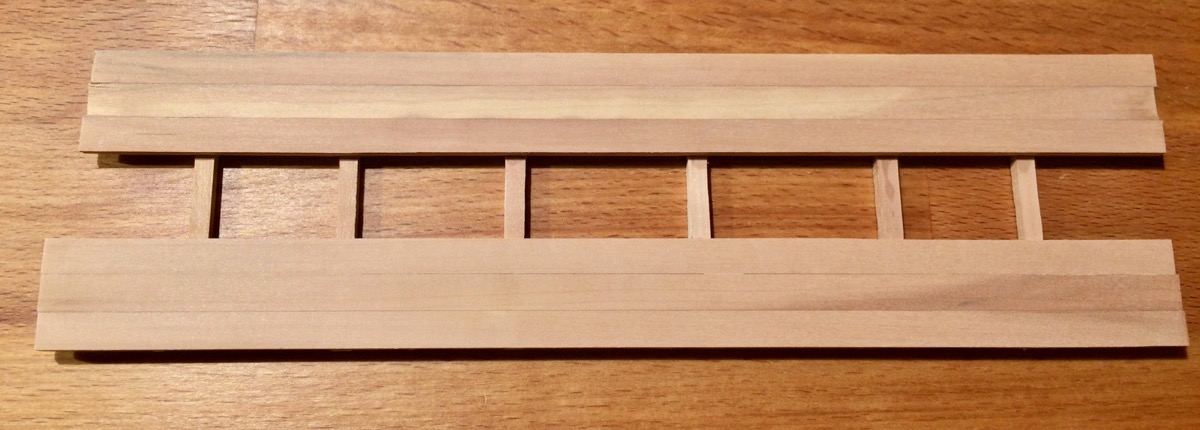
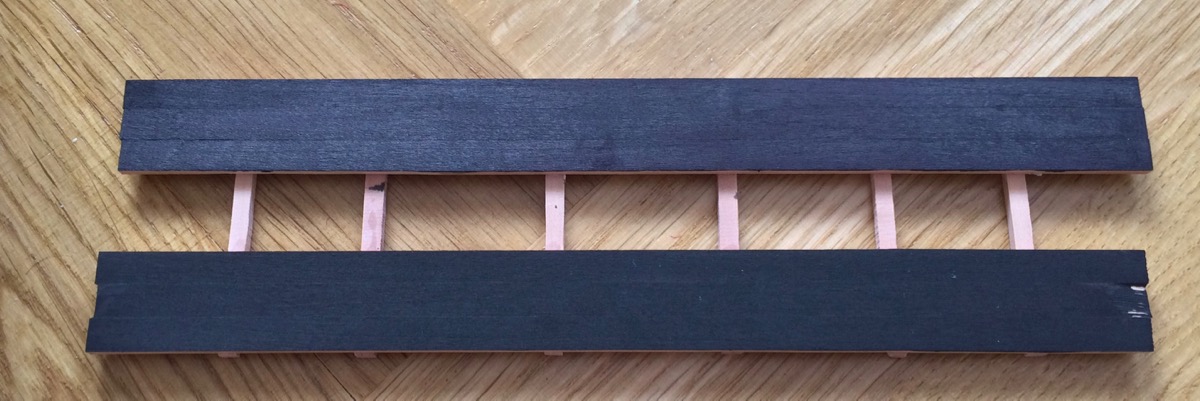
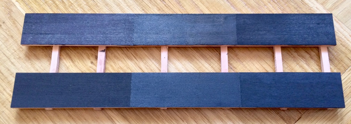
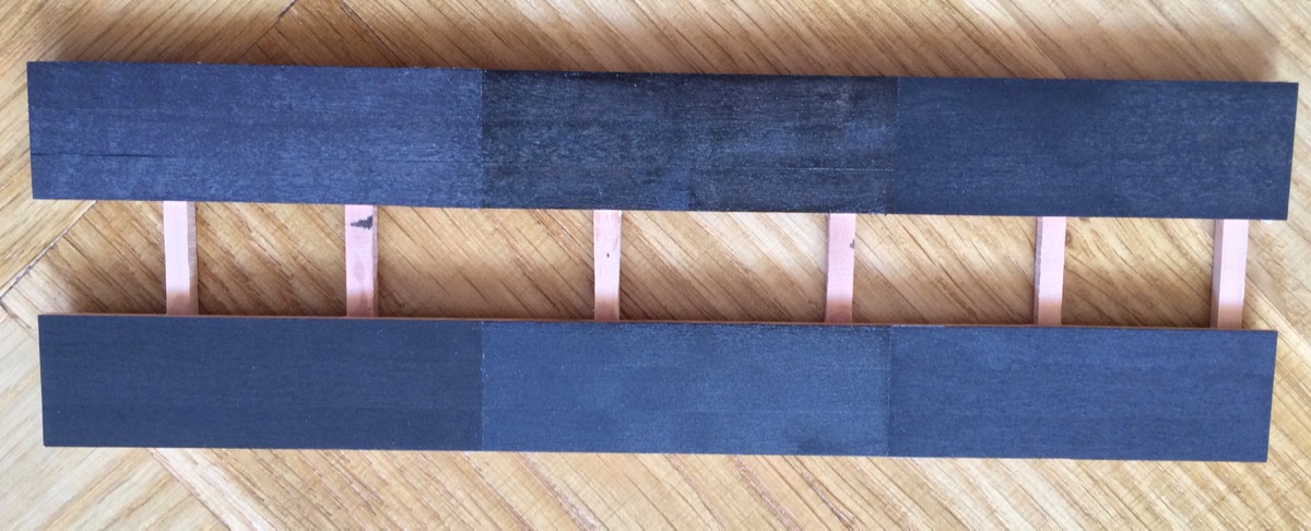
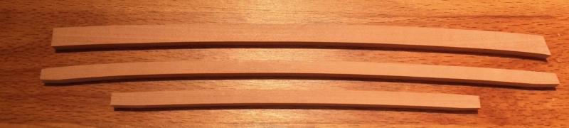
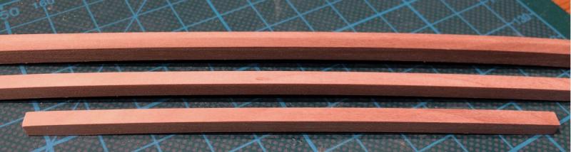
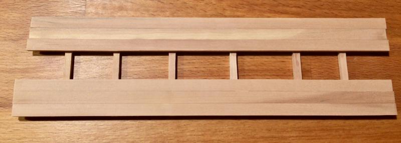
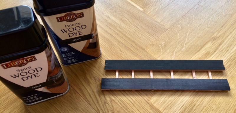
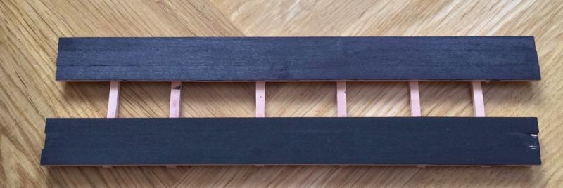
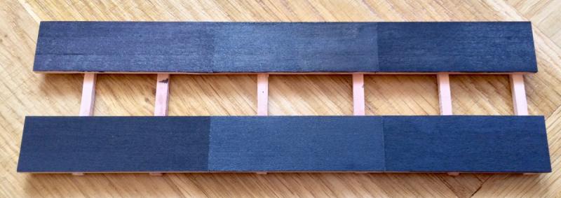
In a meanwhile, tested different ebony dyes on pear. This is a lighter pear, the one that was included into the timbering set from Lumberyard. Should be perfect for the purpose, colour deviation makes no difference if you put a dye on it Found two dyes available, both from Liberon, one is water-based, another is spirit-based. Water-based works as I expected, but does not penetrate the wood deep enough. The spirit one is very weird, not a uniform structure, looks dirty and does not give a consistent colour. You can't apply multiple coats of it, the instruction says "second coat can tear out the first coat". But penetrates the wood better than the water-based (cut off a few slices to check that). Okay... On this photo, spirit-based dye is in the bottom, and water-based is on top, near the corresponding can: Close-up (sorry, on this photo and all other photos - water-based is in the bottom, spirit-based is on top): Then applied different finishes on them. Again, water-based dye is in the bottom, spirit-based dye is on top. Left side - no finish applied at all. Center - three coats of danish oil Right side - two coats of tung oil. Now I will cover half of each section with the paper, and put this test piece into direct sunlight for a while, until it would be a time to install wales. So I probably have a year The idea is to see how a certain finish will change over time, exposed to UV. Will follow up!

- 969 replies
-
- 16
-
-
- hahn
- oliver cromwell
- (and 1 more)
-
I got a few questions "where to buy the kit". My friend bought it in Russia and gave it to me, it is a cheapest option. I also found it on ebay, the seller has a 100% rating and looks like a producer of the kit. So maybe buying it directly from the producer via ebay is better. ebay.co.uk: http://www.ebay.co.uk/itm/mk0302p-Schooner-Polotsk-Wooden-Kit-wood-ship-1-72-model-master-korabel-/112015347120 ebay.com: http://www.ebay.com/itm/mk0302p-Schooner-Polotsk-Wooden-Kit-wood-ship-1-72-model-master-korabel-/112015347120 It is a "plus" version (with a boat kit included, and a better block quality), so a bit more expensive. The kit I bought is a regular one - no boat and the blocks are simpler.
-
That is a very pedantic wood sorting! Does not look like an accident that planks with a bit darker tone and perfectly symmetrical!
-
Thanks everybody for the encouragement! Yes, we are talking about what the online communities are, what the build log is, and she is going to make the photos (and maybe a comment) for the next post It is good to know that our community is really the best when it comes to kindness and sharing!
-
This collective modelling brainstorm is a true joy to read! Thank you for sharing with that level of details!
- 749 replies
-
- 5
-
-
- albertic
- ocean liner
- (and 2 more)