HOLIDAY DONATION DRIVE - SUPPORT MSW - DO YOUR PART TO KEEP THIS GREAT FORUM GOING! (Only 27 donations so far out of 49,000 members - C'mon guys!)
×


EdT
-
Posts
2,214 -
Joined
-
Last visited
Content Type
Profiles
Forums
Gallery
Events
Everything posted by EdT
-
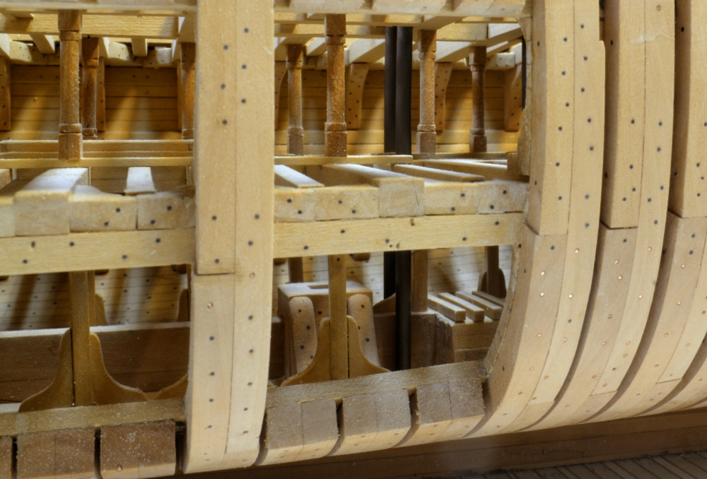
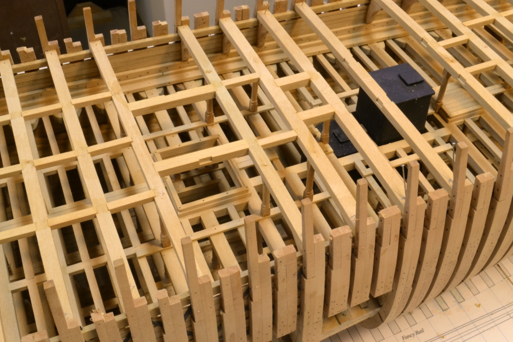
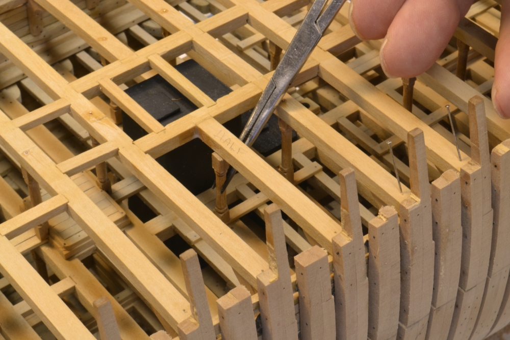
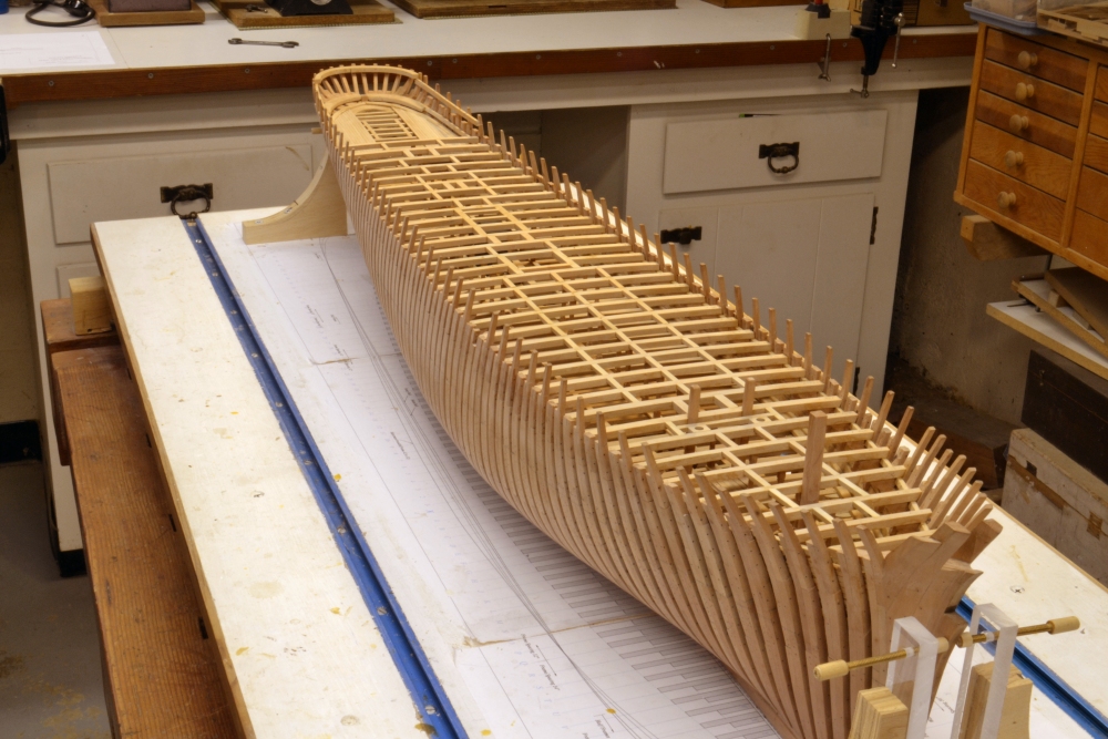
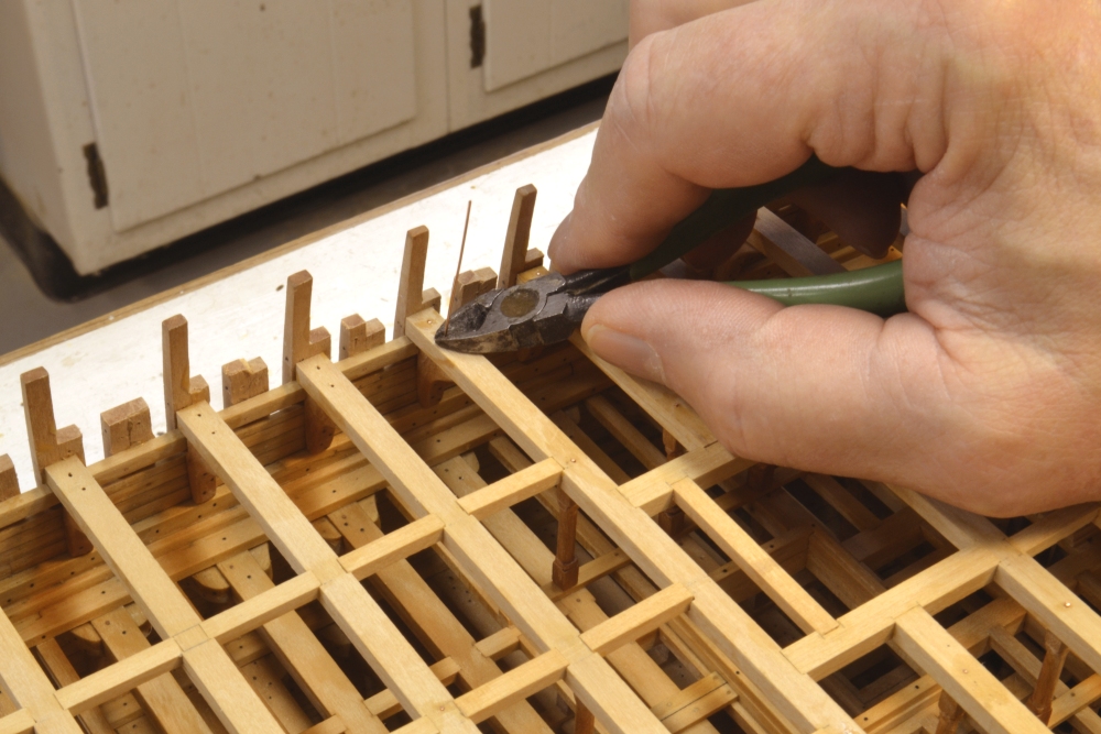
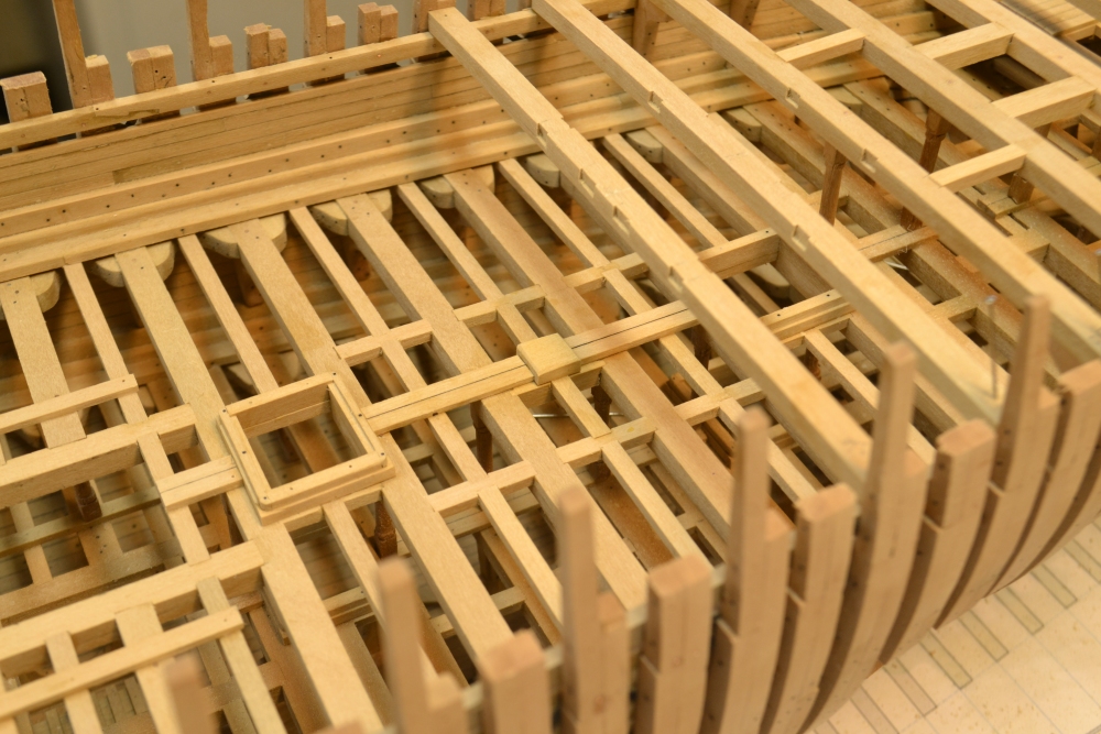
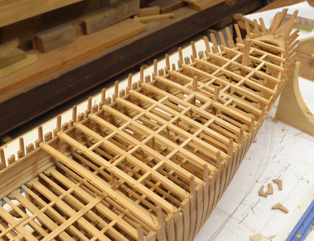
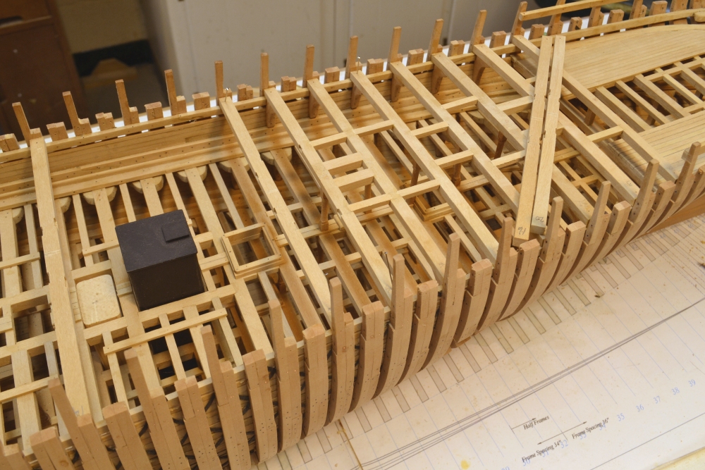
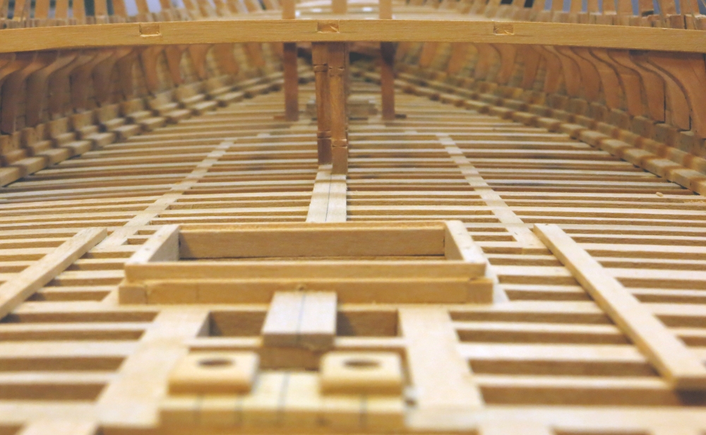
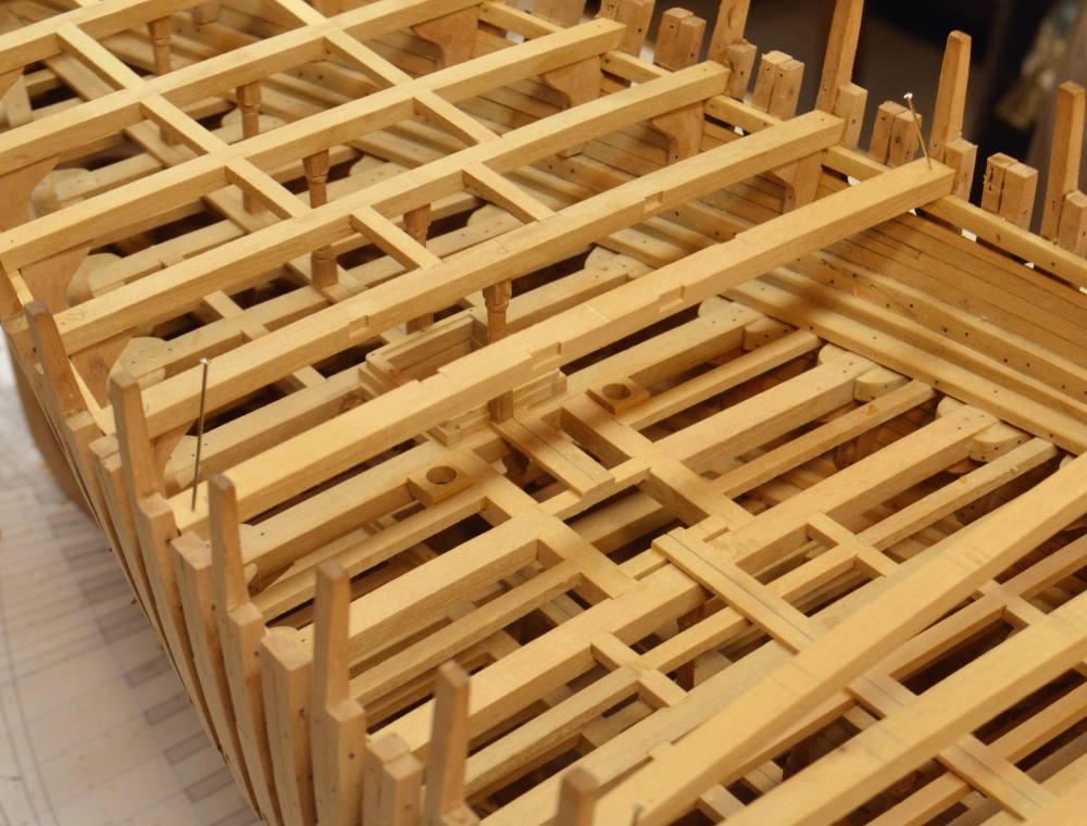
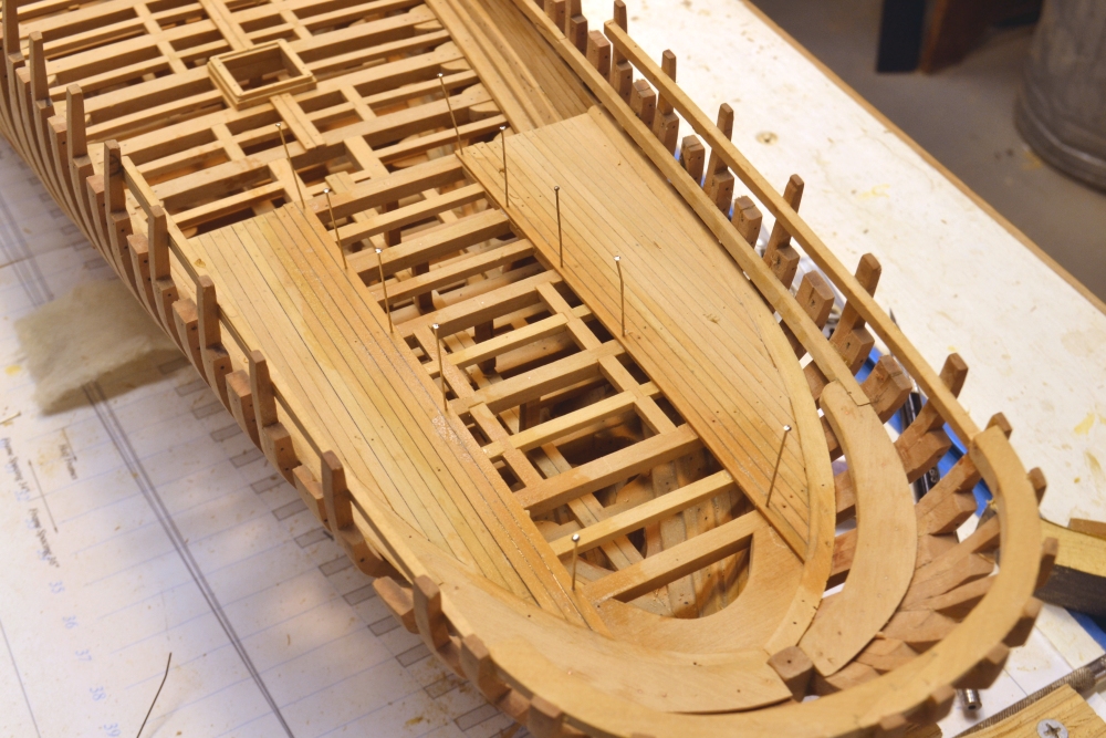
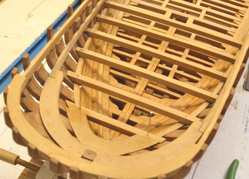
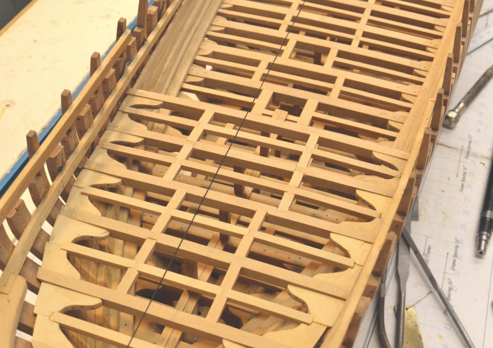
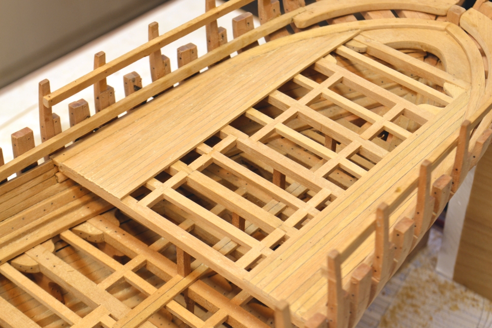
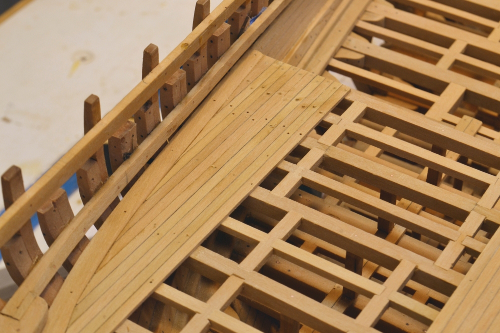
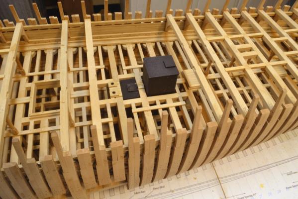
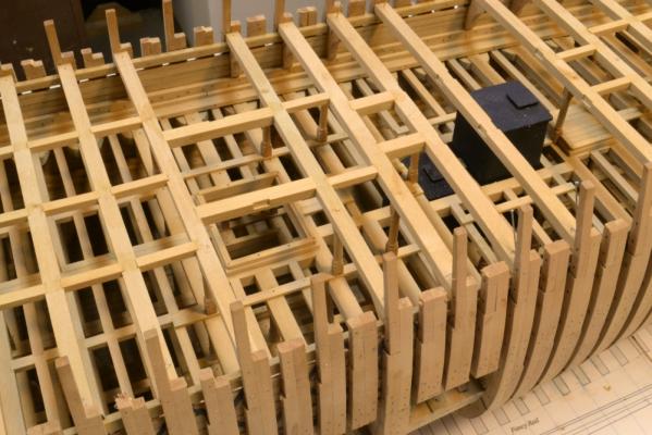
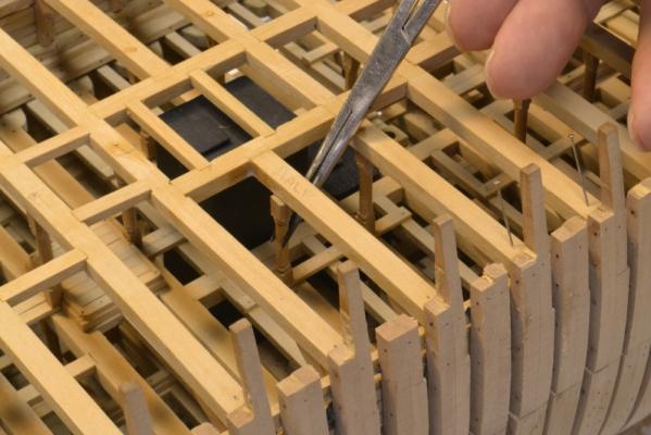
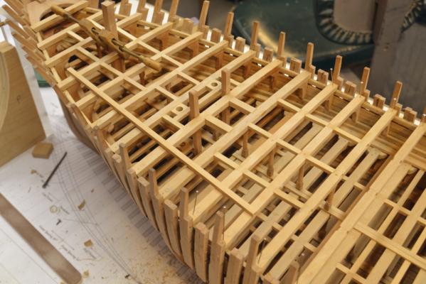
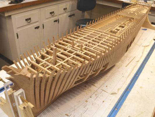
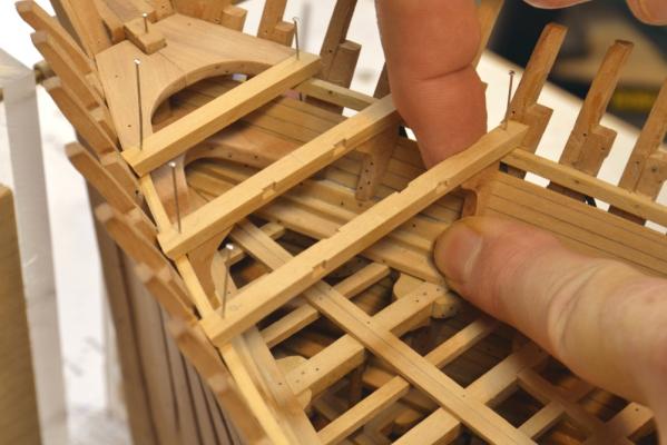
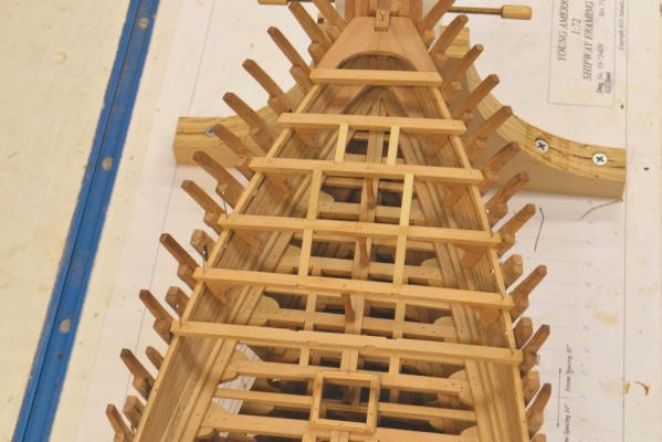
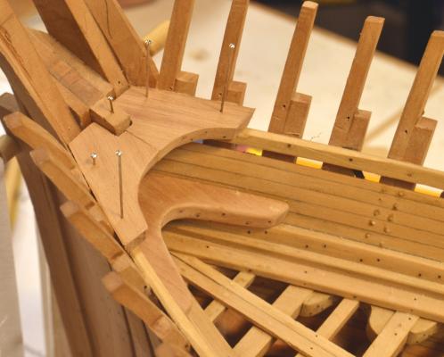
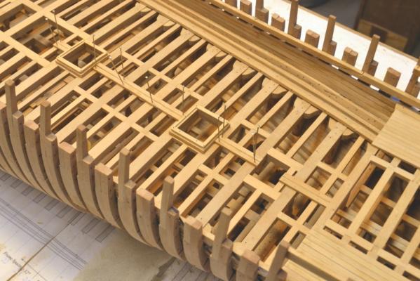
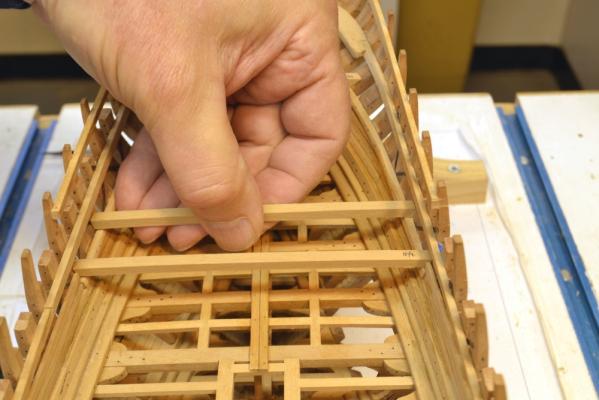
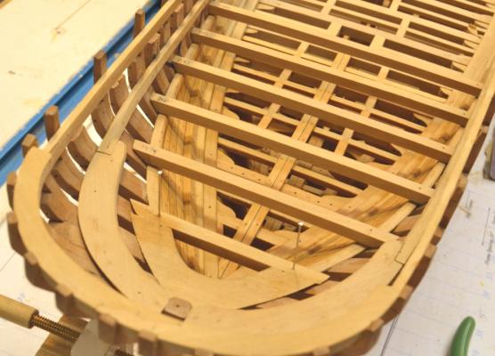
Young America - extreme clipper 1853 Part 93 – Main Deck Framing 4 The two large fresh water tanks needed to be permanently installed before the main deck framing could be completed. The first photo shows these two tanks in place. The tanks were iron and rest on heavy wood bases in the hold over the keelson. These bases were shown in earlier posts. The tanks were made from cardstock glued on to wood blocks. The picture also shows tops of the lower sections of the bilge pump suction piping just forward of the tanks. The next picture shows the run of these pipes down to the limber channel. The pipes are copper tube. The upper sections between these pipes and the pumps on the main deck will be installed later. The 4”x4” dunnage timbers on the base for the forward tank can be seen in this picture – taken before setting the tanks - just aft of the pipes. The main mast step can be seen just forward of the pipes. (This was shot at an aperture of F32 and very slow shutter – much better field depth vs. the pictures in last post.) In the next picture the framing in the midship area is approaching completion. All of the full beams have been installed in this picture including their hanging knees and pillars. In the picture the headers for the main hatch - with scores cut for the half beams - have been fit as well as the main mast partner carlings. In the next picture the framing over the tanks has been completed and the last pillar under one of the half-beams is being test fit. All of the pillars are pinned with copper wire bolts top and bottom. The fitting of this last pillar finishes the deck beam setting. The next picture shows the hull with the main deck framing at this stage. Next will come the lodging knees for all these beams and the ledges – but first a few housekeeping items needed to be taken care of. One of these was literally a housecleaning of the workshop that might be partially noticeable in the above picture. This tidying up also included installing 10 dozen or so functional copper wire bolts with epoxy to further secure the main deck beams and knees. One of these is being installed in the next picture. There are two at the end of each beam – one through the beam into the clamp and one through the beam into the hanging knee. The other task was to apply wax finish to all of the structure from the middle deck up to just below the main deck beams. This cannot be done easily after the ledges are installed. The deck framing has not been sanded at this stage as might be noticed. This will be done once after all of the ledges are installed. Ed

- 3,618 replies
-
- 49
-

-
- young america
- clipper
- (and 1 more)
-
Neat work, Danny. Love the step blocks onn the fore tack. Ed
-
Thank you both - and again the 34 "likes." Not to worry, Allan. There will be plenty of the ship left unplanked. This is a good idea for more than one reason. The planking on these ships was generally only about 6" wide - double the work. Ed
- 3,618 replies
-
- 4
-
-
- young america
- clipper
- (and 1 more)
-
Juergen, I have not looked at your Triton build yet but I wll. There are so many that it is hard to keep up. Cheers, Ed
-
Thanks so much for all these comments and "likes" - and thanks, Andy, for your assistance with my vocabulary. I had not heard that term before and wonder if it was in use in the 1850's - something else to check. Those interior photos seem to be popular. Maybe I'll try some at F36 for more depth of field. Don't know about the light for that though. Thanks again, Ed
- 3,618 replies
-
- 3
-
-
- young america
- clipper
- (and 1 more)
-
Just catching up with your build, Juergen. Lovely work. Great work on the wale planks. Ed
-
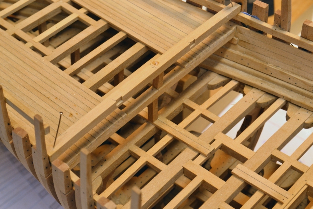
Young America - extreme clipper 1853 Part 92 – Main Deck Framing 3 Framing of the main deck continues from forward and aft. Additional operational features are also being installed. In the first picture the topsail sheet bits and two round openings for the anchor chain chutes are installed. The samson post is being glued in place toward the bow. This very large timber extends up above the forecastle deck. It will support the lever arms for the anchor chain winch located on the main deck just below the forecastle break. The levers were operated from the forecastle. Working just one step behind the drafting sometimes causes problems. The next picture shows the step for the main capstan, which I neglected to install when framing the middle deck. The decking between the two hatches and the middle bay of framing had to be removed and reworked to include support carlings and the square step itself. The next picture shows the extent of the main deck framing at that time – a few days ago. The next picture is a different view. The three rows of carling under the deck cabin can be clearly seen in this picture. The cabin will extend some distance further aft than the beams installed here. The next picture shows some additional progress on the aft part of the main deck. The members that will support the capstan on the main deck have been installed including two large support carlings. The design of these supports and the step is speculative. It will soon be time to make the smaller forward water tank and install both iron tanks while there is still access. The bilge suction pipes will also need to be installed soon. The next picture was taken while I could still place a smaller camera on the middle deck. The view is forward along the middle deck In the foreground is the main hatch and the bilge pipe openings. The dark areas along the waterways are shadows of the deck beams. The last picture is one of those scary close-ups taken through one of the view ports. This was taken at F8 – the smallest aperture on the smaller camera - so the foreground is out of focus, but the detail of the knees on the middle deck framing can be clearly seen – also a scarph jint in the deck clamp. Ed


- 3,618 replies
-
- 52
-
-
- young america
- clipper
- (and 1 more)
-
Mark, if only we could remember everything we were taught, we would be truly dangerous. Ed
- 3,618 replies
-
- 2
-
-
- young america
- clipper
- (and 1 more)
-
Again, thanks everyone for the comments and "likes." Mark, thank you for the question. It is an interesting one - as are most of those that compare Naiad with Young America. There were so many factors influencing the differences in these ships - their mission, difference in time, design preferences - and even attitude - between British and American builders, forest resource availability and of course the basic design parameters - length, width, rig, etc. To answer your question, Young America was comparable in breadth to Naiad being only a few feet broader (43' vs 39'). However YA was almost 100' longer (243' vs 147') - so the L/D difference is striking. It is easy to see why hogging was such a major issue in the clippers. Naiad's model deck framing was based on Steel - number of carling tiers, sizes of members, etc. I based Young America's framing on practices of the time and on Challenge - Webb's well documented clipper of similar size launched a year or so before YA. In general - for YA - I applied the rule that ledges would be less than one third of maximum deck breadth - usually less. I think deck loading on clippers could be quite high, even considering the ordnance weight on 18C RN ships. Considering the breadth similarities, members on YA were much larger. Here are some comparisons of YA's middle and lower decks vs. Naiad's upper (gun deck). Naiad: Beams: 13"wx11"deep. Carlings: 7 1/2"w x 6 1/2" deep. Ledges: 4" w x 3 1/2" deep. Young America: Beams 17w" x 14" deep. Carlings: 10"w x 7" deep. Ledges: 9"w x 7" deep. These differences are pretty striking - especially beams and ledges. Looking at ledge length at midship: Naiad: 7 rows, avg 5' 5" long. YA: 3 rows, avg ~12' long. Deck thickness: Naiad: 3". YA: 3 1/2". We could probably speculate endlessly on the reasons for these differences. They are quite interesting to be sure. Thanks for the question. It gave me a chance to make a comparison I never seemed to find time for. Ed
- 3,618 replies
-
- 5
-
-
- young america
- clipper
- (and 1 more)
-
Toni, Sorry if my comment was confusing. What attracted my attention and what seemed incorrect to me was that the bottom planking extended up past the wing transom, instead of ending on that member with the crosswise counter planking filling the area above (below in the picture of the inverted hull). (I do note that I carelessly said upper plank of the wale in line 3 instead of lower plank.) I understand that the wing transom lies between the lower and upper lines of the wale on this class. I checked that on (a very small) image of the as-built sheer draft for Fly. Depending on how the wale on your model was planked that may well require a triangular filler. I cannot comment on that, but would assume that filler to be part of the wale. I would also expect all of the wale planking to extend just past the last cant frame (after fashion piece) so the ends of the counter planking butt into that excess length. In the picture you posted it looks like the lower strake of your wale beds on or slightly above the wing transom, but with the black paint it is hard to tell. In any event my comment was primarily concerned with the overextension of the bottom planking below the wale beyond the wing transom. Sorry if this was not clear. Ed
-
Toni, I may be off base here but something doesn't look quite right. Aside from the need for a triangular filler between the wale and the first plank, shouldn't the planks end on the wing transom with the lower counter fully planked cross wise down to the wing transom? With the fore and aft planking terminated at the wing transom, I believe the first plank can be made to follow the upper plank of the wale to bed neatly on the wing transom without difficulty. I do not have the Swan drawings but I believe what I described was normal practice - probably to avoid the extreme bends necessary to wrap around the butt ends of the wale. Ed
-
AP, I like the correctness and precision in your drawing the arcs of the hull profile. Well done. On the stem joints, I would agree with Druxey on staggering the joints. Sometimes I think we take the draftsman's construction detials like joint lines shown on the drafts too seriously. I would think the shipwrights had their own ideas as well as standard practices and applied them to the work. I also think actual timber available may have affected these "shop floor" - or should I say "mould loft" - decisions. Ed
-
Thanks, everyone. E&T, the use of iron developed more slowly in America with its huge forest resources and its then small iron industry. Long practiced and available woodworking skills probably prolonged the use of wood especially in the smaller towns in New England where many of these were built. I do not know if there was a shift from wood to iron knees or if complete iron framing emerged to replace the wood structures. I have seen no evidence of iron knees used on American wooden clipper hulls, but I have not specifically looked for it. In the 1850's - when most of the American clippers were built - I believe it was all wood - except of course for the tons of iron bolts. Ed
- 3,618 replies
-
- 1
-
-
- young america
- clipper
- (and 1 more)
-
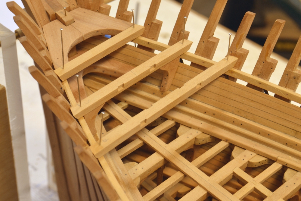
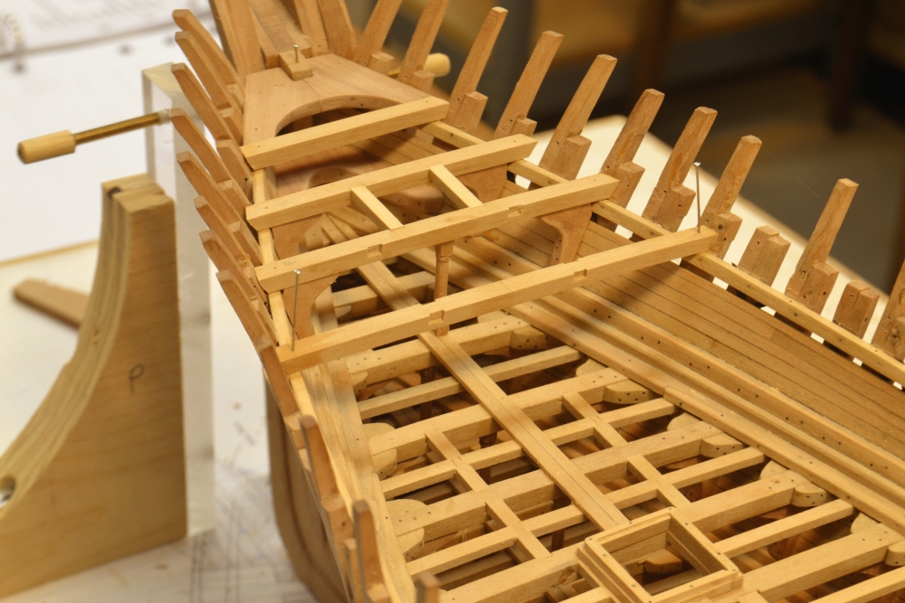
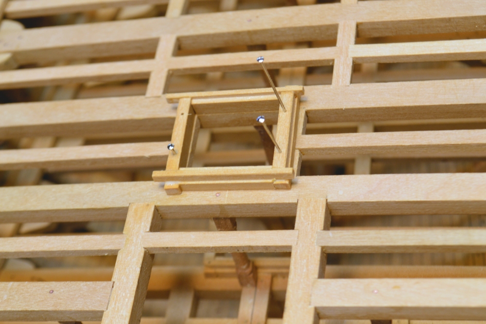
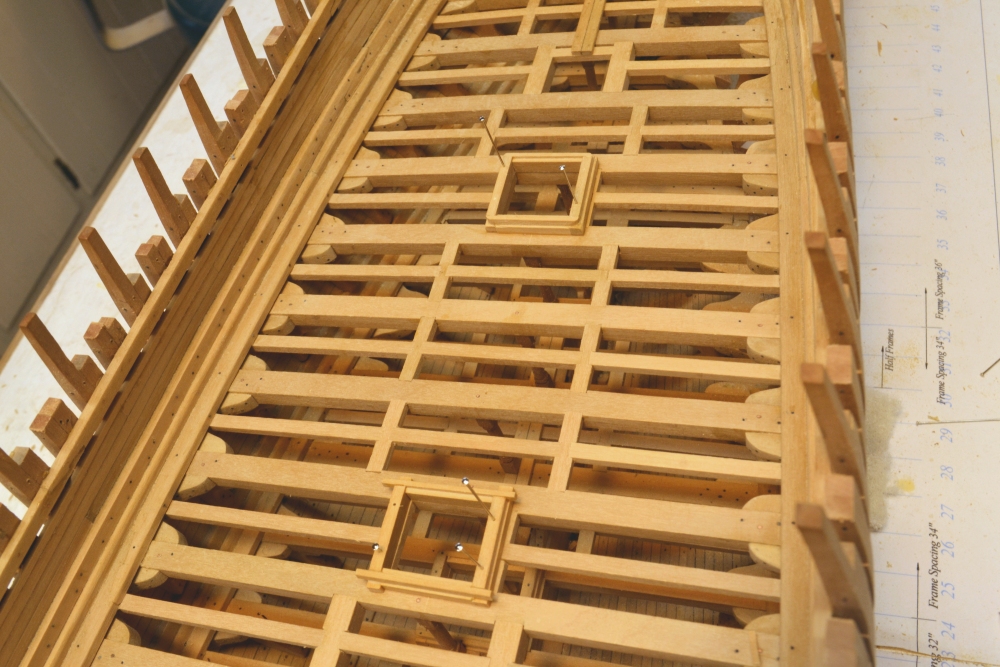
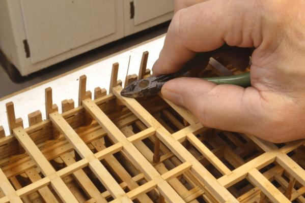
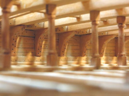
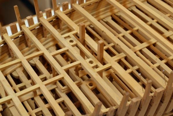
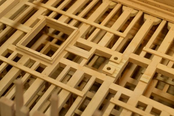
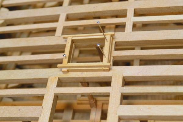
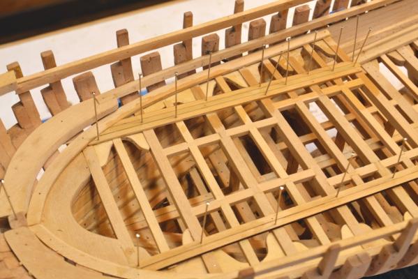
Young America - extreme clipper 1853 Part 91 – Main Deck Framing 2 The first picture shows the most time consuming step in framing the deck – fitting the hanging knees under the beams. I have been doing a lot of this lately. After fitting the knee its bolts are installed at the workbench, it is sanded smooth and then glued in place. Later it will be further secured with two functional copper wire bolts – one down through the beam and another through the frames. The next picture shows a few more beams installed with their carlings. The next picture shows the aftermost beam on the main deck – at frame 36. There will be a few steps down to the cabin deck and a few steps up to the poop at this location. A transverse bulkhead will be installed from the main deck to the poop deck. The cabin deck will also be closed off from the hold with internal partitions. The next picture shows some other work being done as the beams are installed. Chocks with circular holes have been installed just aft of the fore hatch. The anchor chain tubes will fit into these holes and extend from the main deck into the chain storage area in the hold. The next picture shows more main deck beams fitted and some additional details installed. The two bored chocks at the main deck have now been installed – also the topsail sheet bits. Finally in the next picture - aft of the main hatch - framed, bored openings for the two bilge pump suction pipes have been made and installed. These pipes will extend down to the outer planking in the limber channel just aft of the main mast step. The plank strakes outside of these openings are for the pillars under the main deck. Ed


- 3,618 replies
-
- 28
-
-
- young america
- clipper
- (and 1 more)
-
Sounds like you are being challenged, Mark. Sharpen up those gouges. Very interesting geometry, by the way. Ed
-
Thank you, Druxey. You're very kind. Thanks Sherry. Good to see you back. And thank you, Allan. There are two answers to your question. Part 1: The beams start out at the same size because of the process. I start with a chunk of Castello about 2" thick (actual) and long enough for the longest beam, then slice off 2" (actual) wide blanks and finish each at a thickness equal to the sidings of the beams - for YA main deck 12", 17" and 15" depending on location. Each blank is then clamped in a template/fixture and one edge faced off on a router table to the round up - i.e. 6" in this case - to produce the rounded top of beam. The depth of the beam is marked out from this upper curve, the beam is parted off on a scroll saw and then finished to final depth by passing (upside down) through the thickness sander. This produces a finished beam except for length. All this is repeated until the blank is used up. I used this process on Naiad and described it fully in Vol 2, including alternate methods for those without a router table. I believe there is a picture of the template/clamp in an earlier post. The method is fast and almost fool proof. Part 2: The beams in the picture are way too long because rather than cut another (smaller) chunk of 2 x 8 Castelo, I decided to to use a piece already cut, but somewhat longer than needed. A few of the beams shown will actually serve for two smaller beams and some for half-beams - but there is still waste. You can't do a lot with these curved cutoffs. Cheers, Ed
- 3,618 replies
-
- 1
-
-
- young america
- clipper
- (and 1 more)
-
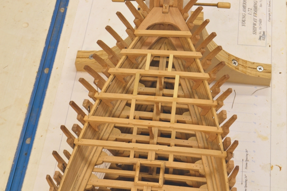
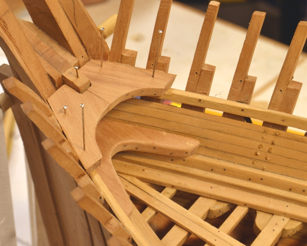
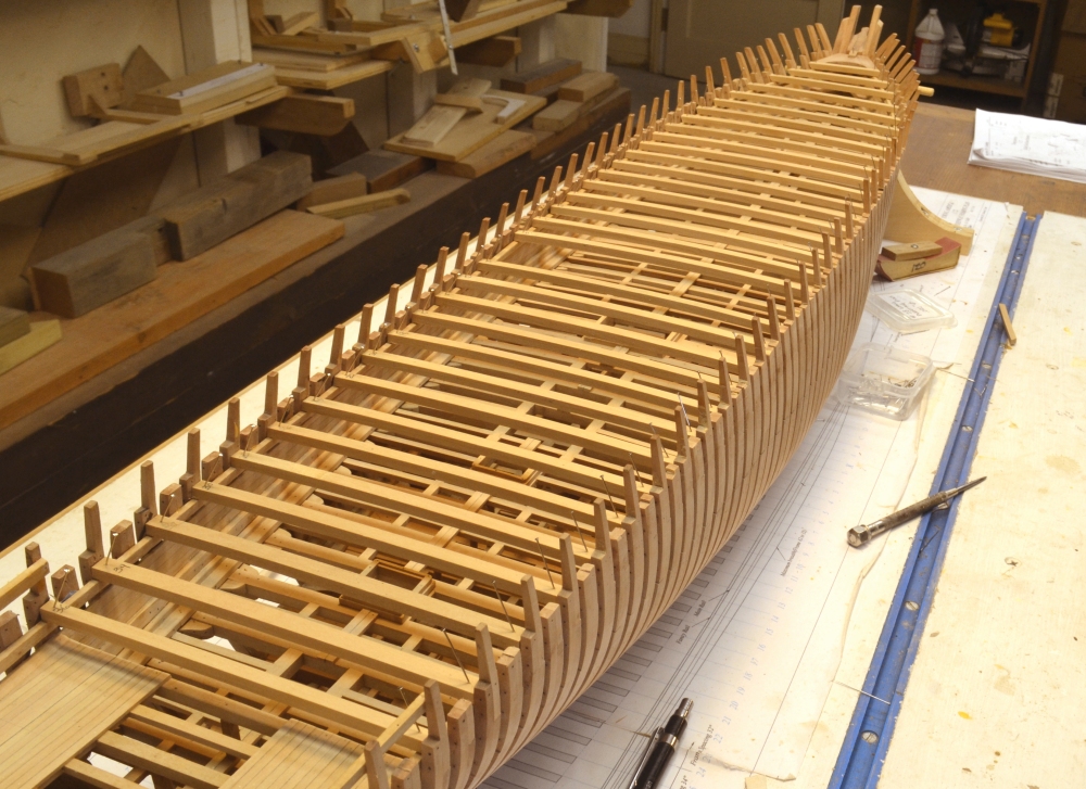
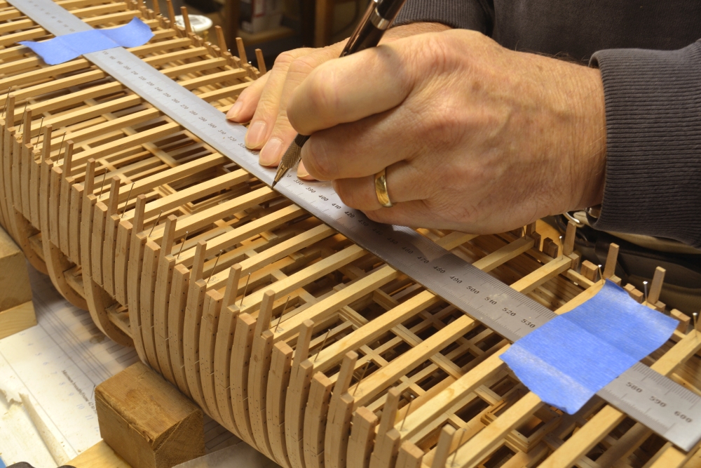
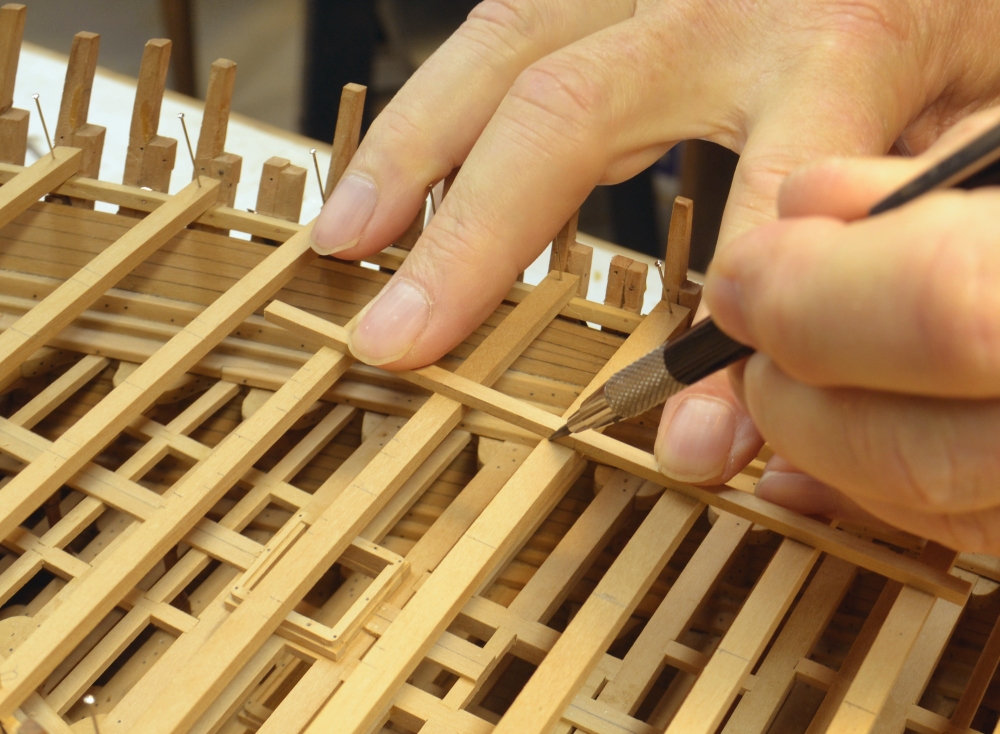
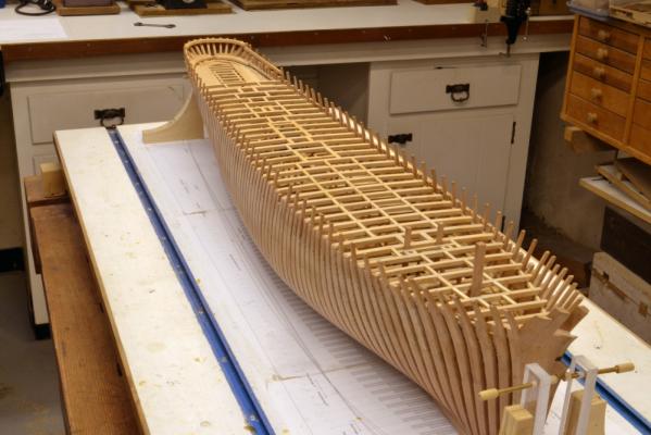
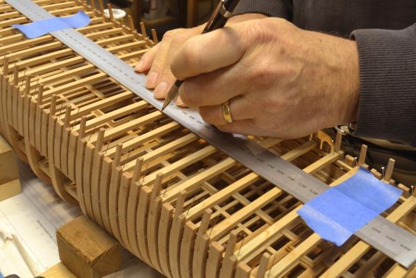
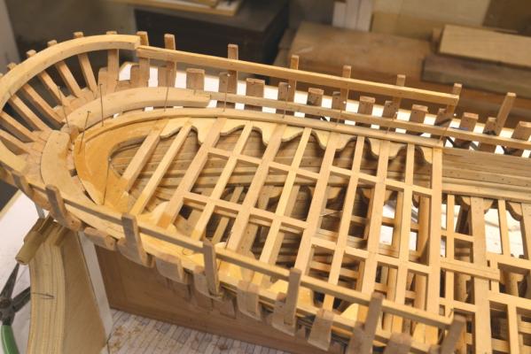
Young America - extreme clipper 1853 Part 90 – Main Deck Framing 1 Again, many thanks for all the nice comments and "likes." In the first picture, the breast hook between the middle and main decks has been installed and the main deck hook is being fitted. The main deck is the weather deck aft to the break at the beginning of the poop. The forward section is covered by the forecastle. I made the deck hook in two pieces to save on wood and was not too particular about the way the pieces are joined since this will all be covered by decking and the forecastle. The side planking treenails in the picture have not been sanded off yet. The first major task on the main deck framing was to make the beams. The full set is shown in the next picture. I have described the method for cutting out these rounded up beams in previous posts. It is very fast and very accurate. The set shown were made in less than two hours starting with a 2” thick block of Castelo. The process, including tools and fixtures, was fully described in Naiad, Vol II. In the next picture the beams have been cut to size, fitted and pinned in place. Most of these beams are 15” wide except for those at the mast partners (17”) and those nears the ends (12”). All are 12” deep. On the original ship they were hard pine – as were all the beams and much else. Frames were white oak and most of the knees and hooks white or live oak. The next step was to mark the centerline on each beam. The next picture shows the last and easiest step in the process that begins with a string line between pins on the stem and sternpost. Although this process was done for every deck so far, I was a bit tense about the string line falling equidistant between the outside of the frames at each point. It is getting a bit late in the day to fix any problems with this. Misalignments would be very visible on this deck and could create a nightmare when the masts are installed. The mast partners on the main deck must be plumb with the mast steps on the keel and also come through the center of the deck. Fortunately, the centerline was well centered with only very minor remediation, so I am now in a more relaxed state. After a substantial amount of checking, the pencil line drawn above was converted into a permanent scribed line on each beam. In the next picture the locations of all the carling and header scores are being marked out while the beams are still pinned in place. The distances were marked out from the centerline with dividers. In the picture a piece of carling stock is being used to mark both sides of the scores. In the next picture the setting of beams has begun at the bow. The first very short beam will be secured only with lodging knees. The hanging knees with their simulated bolts have been installed on the second beam. The third beam has been glued and pinned to the clamps. In the last picture the third beam - with its hanging knees and pillar - has been installed. The next beam has been glued to the clamps and frames. All of the scores in the beams are cut at the bench by hand before the beams are set – from the marks made previously. Carlings are installed progressively after the knees and pillar on each beam. A period of repetitive work will follow. Most of the time doing this is spent making the hanging knees and fitting them under the beams. Fortunately, some preparation work in this framing for main deck facilities will break some of the routine. So, three down, thirty-one to go. Ed


- 3,618 replies
-
- 32
-
-
- young america
- clipper
- (and 1 more)
-
Addendum 5 - The Naiad Frigate Volume I There is an error on the notes sheet PDF for Drawing 1, The sheer Draft. On that sheet the height of the lower deck at the AP is given as 22’ 4”. The correct height is 18’ 4”. The drawing is correct. Sorry for any inconvenience. Ed
-
Nice to hear from you, Robin. Yes,she is slim and sleek - just 3+ feet broader than Naiad but 100 feet longer. Ed
- 3,618 replies
-
- 1
-
-
- young america
- clipper
- (and 1 more)
-
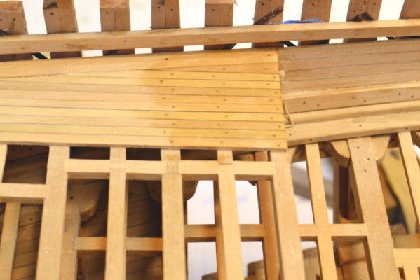
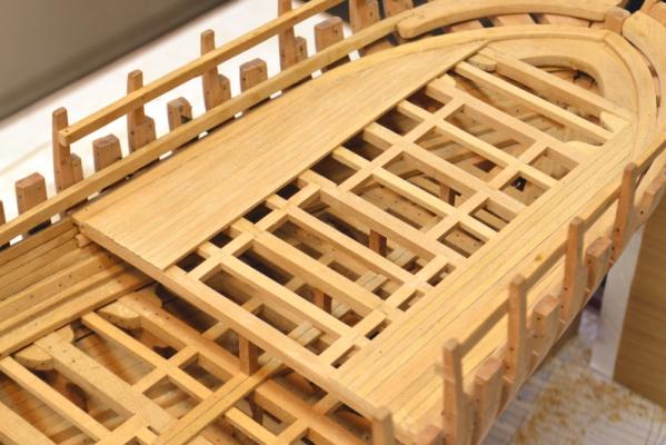
Young America - extreme clipper 1853 Part 89 – Middle Deck Hatches/Cabin Deck The first picture shows some of the treenailing on the cabin deck. These planks are 7” wide. At this width the standard fastening spec was one per beam / ledge. The treenails are about 1 ½” in diameter and are Castelo as mentioned in the last post. The next picture shows a typical hatch being framed. At this scale and on this deck, simple lap joints are used. The head ledges are on top to secure the coamings. These will be bolted at the pin locations, in each corner and in the center of the beam. The next picture shows a coaming completed and being glued down and one still being fabricated. In the next picture the central planks are being installed between the openings for the hatches, masts and water tanks. These planks are needed to support the pillars under the main deck. As with the deck below, no further planking will be done on this deck. The next picture shows some additional planks being installed on the cabin deck. After having completed the drawing for arrangement of cabins, etc. on this deck the final amount of necessary planking can be set so those details can be constructed. I don’t mind covering some of the structural detail in this area because some of it is based on assumptions and its authenticity cannot be verified. The members – clamps, transoms - along the line of the main deck in this area will also be hidden by the cabins and related details as will the ends of the planking that are simply butted against the margin planks. Cabin detail will be discussed later. Ed


- 3,618 replies
-
- 36
-
-
- young america
- clipper
- (and 1 more)
-
I love looking at pictures of your shop, Micheal. It makes me feel right at home - power tools crammed into every space and fitted with homemade accessories, benches littered with delicious clutter, lots of sawdust, etc. Isn't it great to be able to walk away at the end of a session and not have to clean up and restore neatness? Tying frames to the ribbands sounds like a good idea. All the best with the project. Ed
-
Fascinating project,beautiful workmanship. Should keep you busy for quite awhile. Look forward to your progress. Ed
-
Thanks,Karl - and thanks everyone for the"likes". Frank, I'd bet it is the wood species. I have used Boxwood, Bamboo and Castelo successfully using the Brynes/ModelMachines drawplate. I am not pamiliar with African pear. Ed
-
Is there another way, Frank? I ripped off a thin blank from a 2"x2"x24" piece of Castelo, then drew it down to the .021" diameter. Ed
-
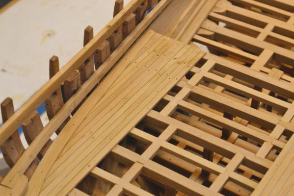
Young America - extreme clipper 1853 Part 88 – Cabin Deck Framing/Planking The cabin deck provided accommodation for senior officers and passengers. In elevation, it was midway between the middle and poop decks – to provide increased headroom. The deck occupies the area aft of frame 36. It is just under 45’ in length on the centerline. The first picture shows beams being fitted. No details are known about the structure of the deck. I have assumed scantlings equal to the main deck – beams 12” x 12”. Also, since the structure is lighter and close to the deck below, I have omitted hanging knees. The next picture shows all six beams installed and awaiting the lodging knees. In the next picture, lodging knees, plain square pillars, carlings and ledges have been installed. In the next picture 12” wide by 6” thick margin planks are being installed around the sides – again no details known, but a reasonable guess. Because the main deck beam at frame 36 will be directly aligned with the beam for the cabin deck and because it is only a few feet above, the deck planking was installed next, while there was still access for drilling. This work has begun in the next picture. I use .021” diameter pins forced into tight holes to secure the planking for gluing. The holes are then enlarged slightly for treenails. I have yet to decide on the full extent of planking on this deck beyond the area of the cabins along the sides. I expect to construct the partitions and built-in furniture for these. More on this later. The aft end of the main cabin between these rows of sleeping quarters will also likely be decked. The next picture shows the completed planking in the cabin areas. The planks are 3½” thick and 7” wide. I did not take the trouble to cut these into the margin plank because bedsteads will cover the margin plank and the first few strakes of decking. In the next picture, treenailing of decking on the port side has begun. The first two rows have been nailed. The third row has been drilled. The treenails are 1½” (.021”) diameter Castello. This has become the de facto standard size on the model. Treenailing of the inboard side planking continues. Ed

- 3,618 replies
-
- 27
-
-
- young america
- clipper
- (and 1 more)