


gkharrin
-
Posts
91 -
Joined
-
Last visited
Content Type
Profiles
Forums
Gallery
Events
Posts posted by gkharrin
-
-
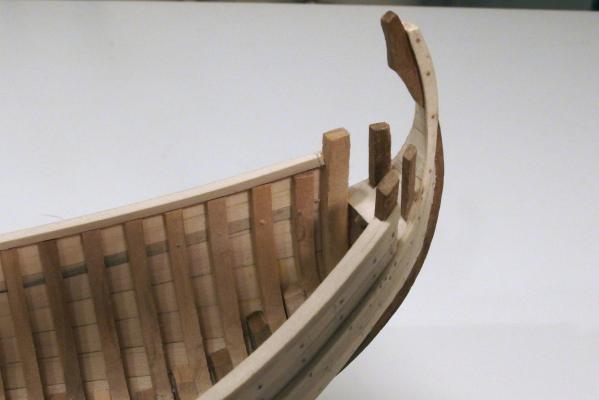
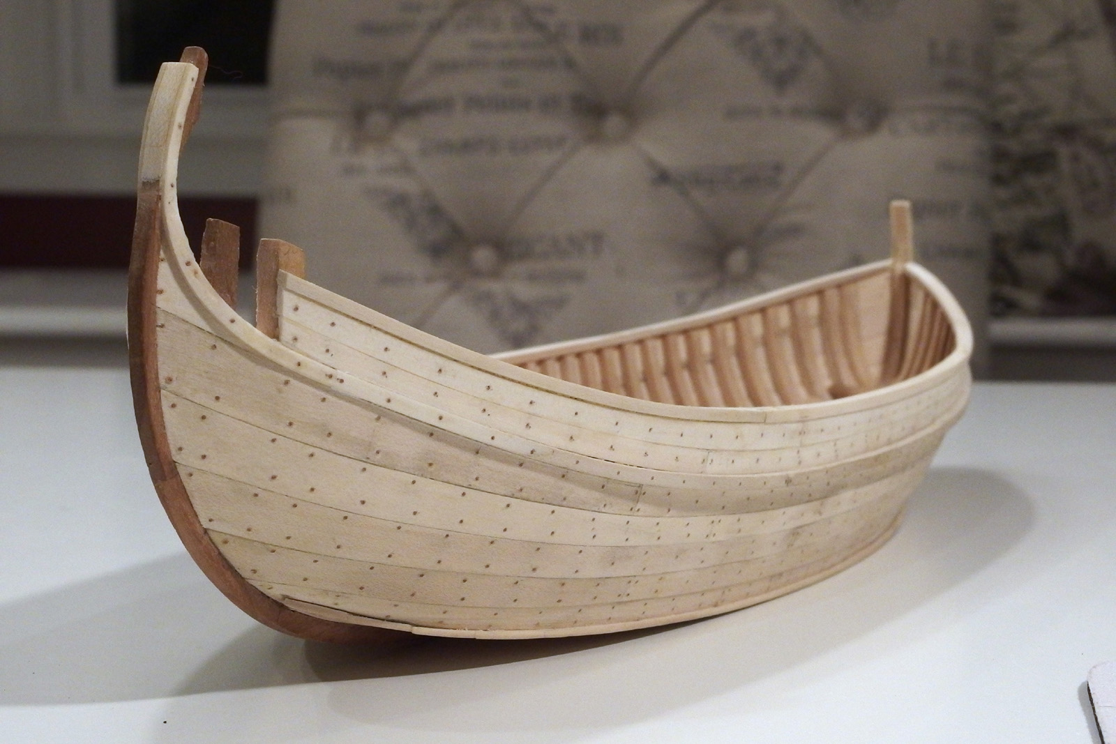
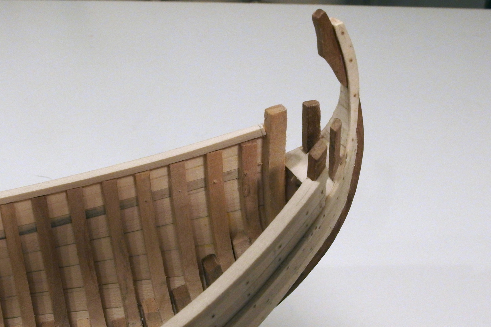
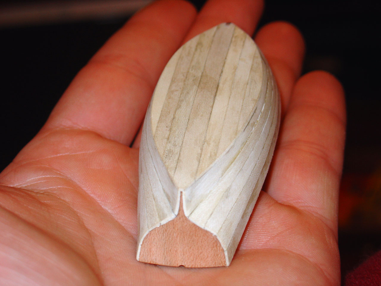
The keel
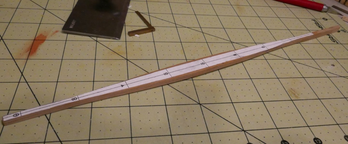
I made use of a knot to have the stem follow the grain a little better
- Paul Le Wol, mtaylor, bruce d and 2 others
-
 5
5
-
With no small amount of extra work on top of the Google results, I have translated two papers about these vessels and one of their builders.
https://www.hrsms.org/Content/dan-viktoria-two-eel-drifters-by-morten-gothche-a-rough-translation/
-
-
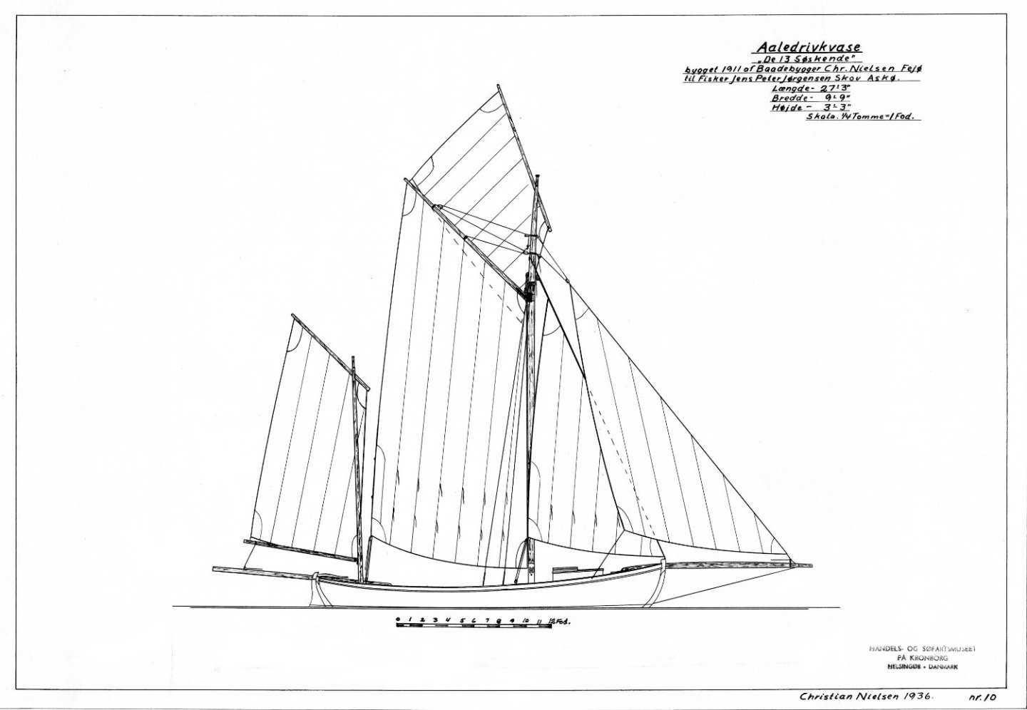
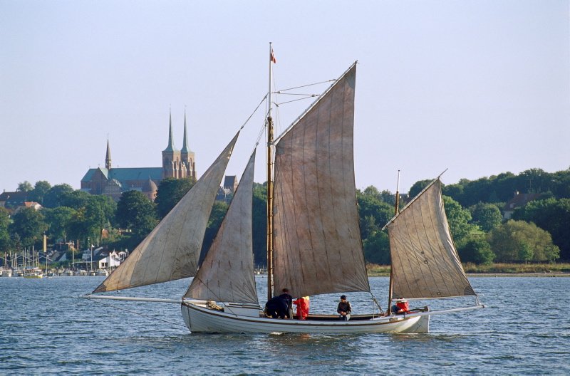
This is a Danish fishing smack built specifically for the eel fishery. She dragged a seine net on the starboard side, the net being attached to the ends of the two spars.
There are a lot more details on the research and construction on my club page, but I will copy some of them to this thread.
- GrandpaPhil, ccoyle, yvesvidal and 3 others
-
6
-
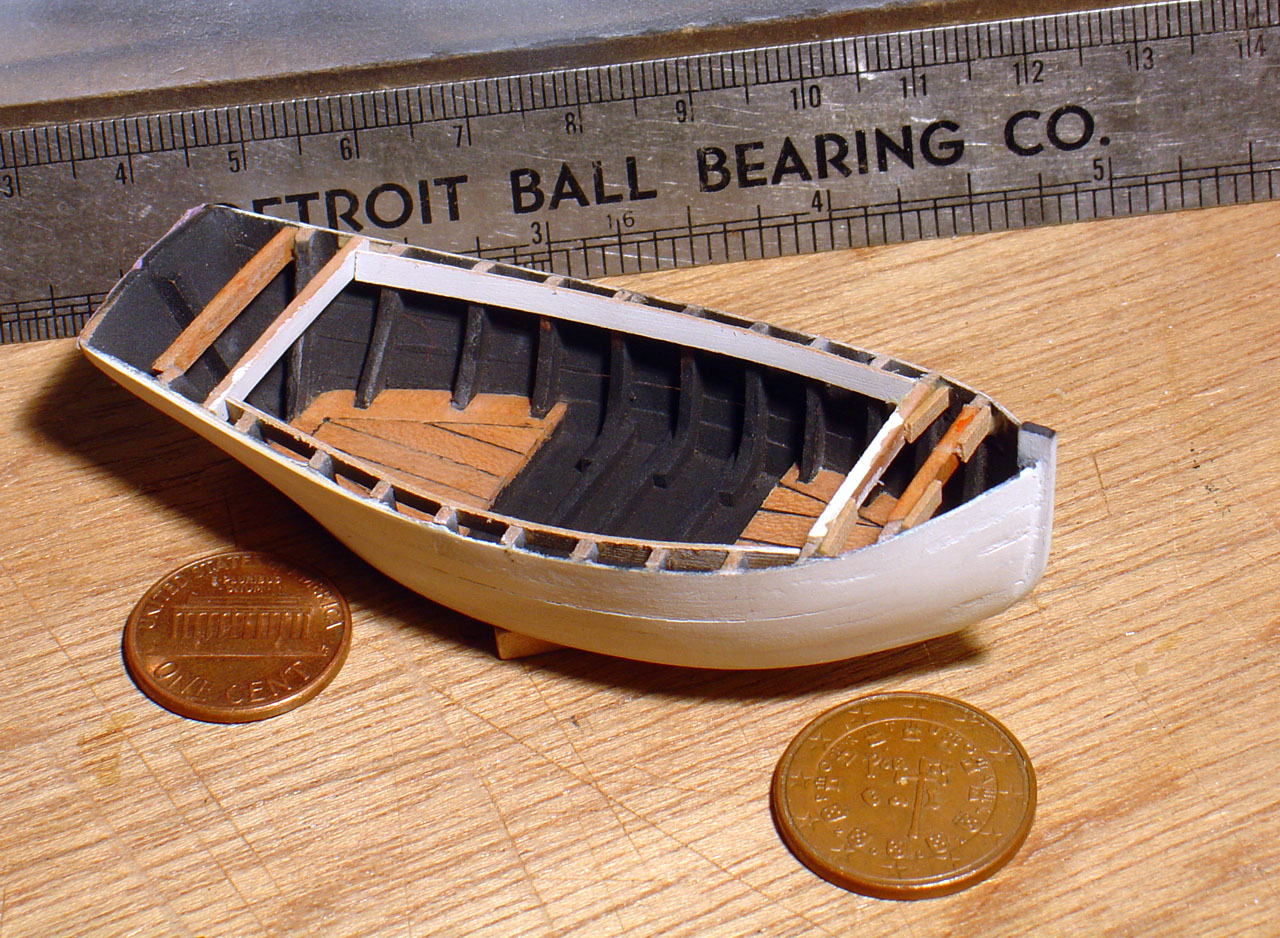
Here are some of the early results on my model.

- mtaylor, Paul Le Wol, ccoyle and 1 other
-
4
-
On 2/20/2021 at 1:02 PM, RobinB87 said:
You can always make them by yourself, i think its a good workout to test you're patience 😅
Its only a suggestion 😉
Thank you for the excellent suggestion, @RobinB87. I've settled on this solution and it is working well. To get the proper diameters, I am doing this separately for both the roves (inside the hull) and nail heads (outside the hull). For easier installation, I am adding them before affixing the planks to the model. I have 2 planks (out of 10) installed on each side. I'll add a build log sometime soon.
-
8 hours ago, wefalck said:
I would dare say that it also depends on how rounded the boat ends are. Don't have access to it at the moment, but didn't Eric McKee say something about this in: MCKEE, E. (1980): Clenched Lap or Clinker.- 30 p., Greenwich (National Maritime Museum).
Thanks for the post and the reference. I looked up "Clenched Lap or Clinker", and it is intriguing. I investigated getting a copy, but the best price is $35 and it is only 30 pages. I may wait for another opportunity.
The stern on this boat is very rounded. But the difference in overall bend is just half the thickness of the plank (if using half laps), so I'm not sure how much a factor the shape is.
I forgot about some photos online of a replica being built. I may be able to scale off an approximate length, but it is hard to determine where the taper really begins. I'll post again later. Now back to my real job....
-
-
Does anyone have references documenting one or more ways the length of the gains for a lapstrake hull is determined?
I found the forum post below that states it is only the last foot. General web searches show various instances between 18" and 30", but nothing as short as 12". I also have a reasonably strong recollection of reading "20 x the plank thickness", but I cannot locate that reference now. The planking is 7/8", so 20 times this would be ~18", putting it in the ballpark of what I found online.If it makes a difference, the subject of my boat is late 19th-century Danish.
Thanks,
Greg -
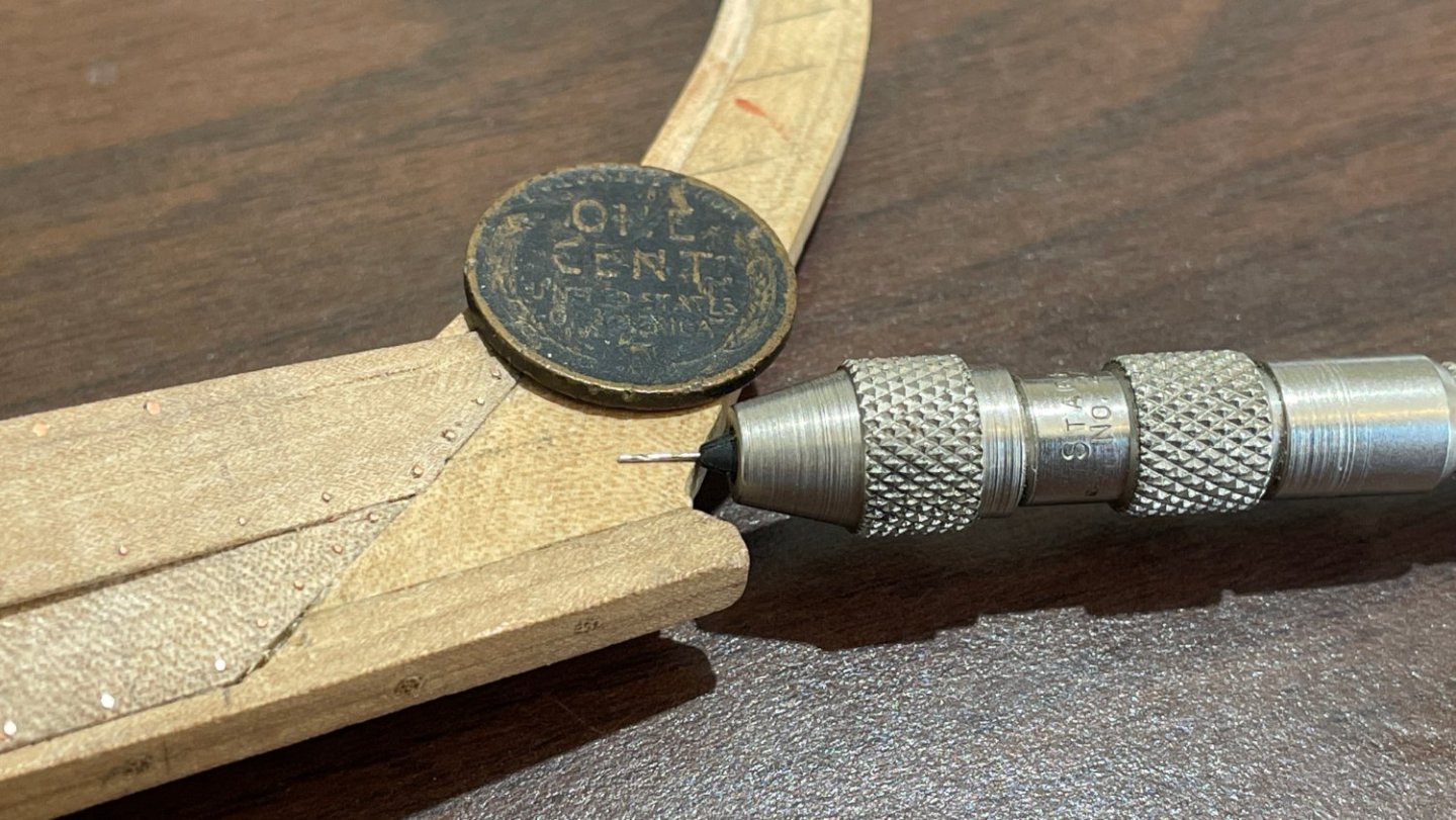
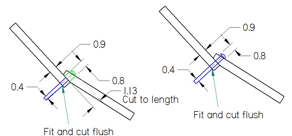
Thanks for the replies. I could use a cup burr or Alexey's method if I were to use two pieces, one to simulate the rove on the inside, and another to simulate the nail head on the outside. These are different diameters (at scale, 0.8 mm and 0.4 mm). The head on the outside will be flush with the planking, so I can simply stick the end of a wire half-way and snip it off. On the inside, I'd have to drill a larger hole just part way through and cut the wire with the rounded end to the final length (~1 mm) before fitting it. That would be pretty tedious.
If I can find the proper sized nail or pin, it will be much easier. As noted above, I have found a proper sized pin, but I'm looking for a less expensive option. I'll need over 1200 pins. At $8 per 50, the ones from Model Motorcars will add up quickly. If I must, I must...
- mtaylor, Archi and EricWilliamMarshall
-
3
-
2 hours ago, druxey said:
That is the source I listed in my original email for the 0.8mm rivets, but thank for the reply anyway.
-
-
13 minutes ago, vaddoc said:
I presume the shank is 0.6 mm, and I need 0.4 mm, but thank you anyway.
-
14 minutes ago, allanyed said:
Model railroad parts suppliers should also be a help
Thanks, Allan. I saw railroad track pins suggested elsewhere, but what I found was too large and made of steel. I'd prefer brass. I appreciate the suggestion all the same, and I'll check the dragger build.
-
Hello,
I am seeking sources for very small nails or pins. I am modelling a lapstrake hull at 1:24.
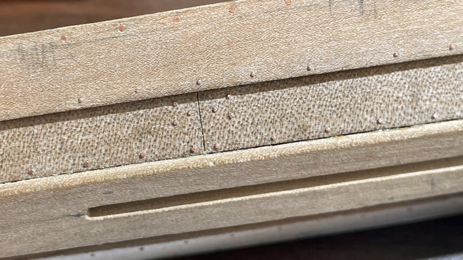
The nail heads @1:1 are 10 mm and the roves on the interior of the hull 19 mm (~0.75" / ~3/8").
At 1:24 these would be 0.79 mm and 0.42 mm, respectively (0.031" / 0.016").
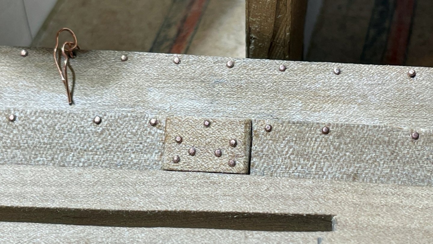
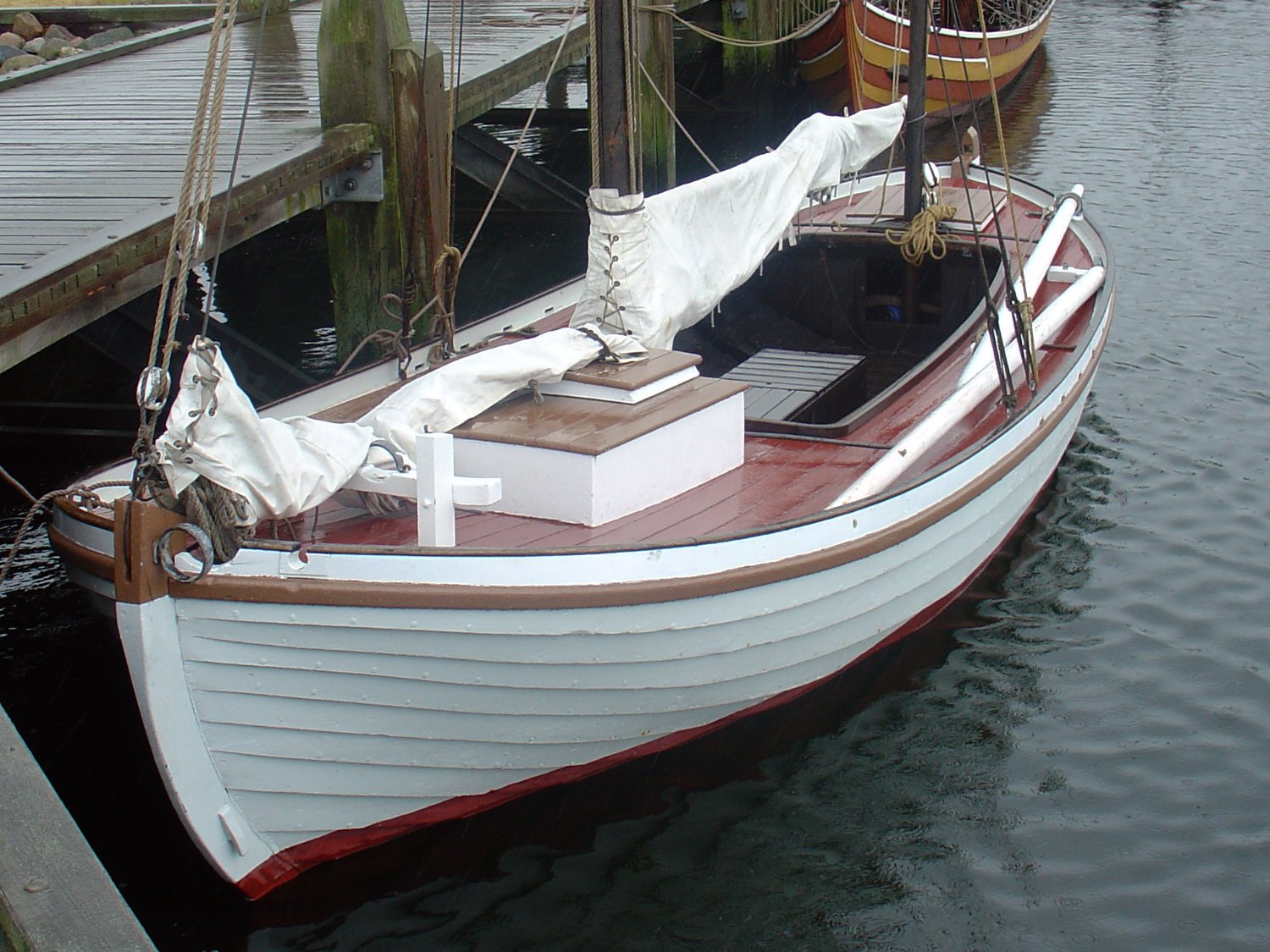
My intention is to use a nail or pin head to simulate the rove and cut/sand the shank flush with the hull to simulate the nail head. I'm confident the simulated roves will add proper detail to the interior of the model. On the outside surface of the hull, I hope that with paint applied lightly enough, the simulated nail heads will still be barely visible - a slight texture variation, not out-of-scale, and more realistic than a perfectly smooth surface. [edit 16 Feb 2022 - I've noticed that on two extent vessels, Viktoria and Dan, the nail heads appear rounded and flush, respectively. Either more or less visible nail heads are equally appropriate.]
I have some small pins that came in a box of stuff bought at an auction. The head diameter is 0.028" and the shank 0.014". This would be a scale error of -10% and -15%, respectively. Reasonable. But I do not have enough to complete the model.
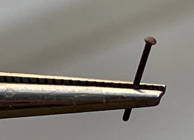
I found a source of scale rivets where the head diameter is 0.034" and the shank 0.016" - scale errors of +7% and -4%, respectively. Closer to scale than the pins I have on hand
However:
a) The heads are more spherical, and roves are shallow cones. These might appear to rise above the surface too much. I could chuck each pin into a rotary tool and sand the hemispheres into cones, but I'd have to do that 1200 times. I might be crazy enough to do it, but I won't mind avoiding it. [edit 16 Feb 2022 - using Michael Bezverhny's technique (YouTube video mentioned below) the nail heads sometimes appear too rounded. I found that just lightly sanding the tops after installation gives the proper impression, and that even with magnification it is difficult to tell the surfaces are flat and not shallow spherical sections]
b) They are $8 for a pack of 50 and $10 for shipping. The total for what I need would be $210. I'd prefer a less expensive option.
To make use of what I have on hand, or to reduce the cost of the rivets, I could only model the roves where they would be visible on the final model - the boat is not completely open. Where the roves are not visible, I can simulate the nail heads with simple 26ga brass wire. However, I like to take detailed photos of the entire process, and though it might sound foolish to you, I'd like each stage to look as realistic as possible. I'm also thinking of future models. I am very likely to build another lapstrake hull to the same scale, and will eventually need more.
So far I have found lots of nails, but none with a shank less than 0.7mm and heads over 1mm. If you know of a source, I'd be grateful for the information.
Thanks for reading!
-
An updated link to Bob Comet's models.
I did my last model this way as well (painted one side, not the other). Zero paint was not an option, since the original was so colorful.
You can also see pictures on our club's website.
Notes:
The MSW link above does not yet have any photos of the unpainted side. I'll add some later. But it shows that the model can be viewed as fully-painted from many angles. For this reason, I would paint a flat transom and any tumblehome on the (mostly) unpainted side.The link to our website is not yet active. I hope to finish it soon.
- Canute, Ryland Craze and mtaylor
-
3
-
I stopped posting in-progress photos because I was frantically working to finish for our club's exhibit at the Mariners' Museum.
I've posted some poor-quality pictures taken in a rush, with inadequate light and cameras that were not up to the job. They're a little grainy if you zoom in, and the depth of field is poor. I hope you enjoy them anyway. I cannot take any more until next year when I get it back.- mtaylor and Ryland Craze
-
2
-
On 4/23/2017 at 5:43 PM, gkharrin said:
I have some questions about the rigging, if there is anyone willing and able to answer.
A friend on a Portuguese forum suggested that this is to control the tip of the yard when lowering it. I was originally thinking the block was attached to the yard. But if what he suggests is correct, it must be on the mast, and this makes more sense.
As the yard is dropped, the line is no longer running parallel to the yard, and it has more leverage.
There is only a line to one side, which implies the center of gravity is farther up the yard than where the halyard is attached. Consequently, as the yard is lowered and the tackle at the foot of the yard is slackened, the top will drop down. The line in question is used (presumably) to keep the yard level. The tackle at the foot of the yard could do the same job initially, but (similar to my original concern at the top of the yard) it looses leverage the more the yard is lowered.
-
Click and you'll see full size and right-side-up
- Mirabell61, G.L., mtaylor and 1 other
-
4
-
-
I have some questions about the rigging, if there is anyone willing and able to answer.
1) I cannot figure out the purpose of the line marked with the red and green arrows.
http://www.hrsms.org/home/dl1288?display

It is not labeled as, and does not appear to be, one of the brails (Carregadeiras da vela, #8). My only guess is that it is intended to bow the yard by pulling on the tip of it, in order to change the shape of the sail (put some "belly" into it). But once drawn tight, it will run right along the bottom of the yard, and a great deal of tension would be required to bend it. I'm not sure that makes sense, but it would play a part in my next theory...
I am also wondering about the purpose of the block indicated by the blue arrow. It seems to be pointless, since the line is attached to the top of the yard, and (according to the green arrow) runs toward the bottom of the yard, though it does not indicate where it terminates. The line does not change directions at the block, and it would therefore only serve to keep it along the yard on the bottom half, while the top half could hang loose, as shown in the image. Why?
My suspicion is that it actually terminates at the blocks indicated by the green arrow in the second image (link below). These blocks are not shown on the plans. It would mean the green arrow in the first image is wrong, and the line travels along the mast instead of the yard. The block (blue arrow, first image) would then serve the purpose of changing direction from along the mast to along the yard. The blocks (green arrow, second image) at the bottom of the mast might then provide the tension necessary to bend the top of the yard. It would be easier to bend if the line did not run along the yard (for instance, toward the stern), but then it would put more tension on the "Talhas do carro da verga" (#3).
http://www.hrsms.org/home/dl1287?display
2) In the second image, there is a line (indicated by a red arrow) attached to the bottom of the yard. It is not under tension, and appears to be attached to a frame on the port side. This appears to be a "preventer". It would prevent the top of the yard from swinging down toward the stern if the "Talhas do carro da verga" (#3) were to fail. Do you agree?
3) This appears to be where the brails ((Carregadeiras da vela, #8) are cleated (blue arrow, second image ). Do you agree? Could all of that sail be lifted without any mechanical advantage from blocks? I guess we've gotten weak in our modern age.
4) The large blocks indicated by the purple arrow appear to be the winding tackle (Estralheira para serviço de cargahere, #6), secured to a different position than is shown in the plans. Here it is at the base of the mast, and in the plans it is to the starboard side somewhat abaft the mast. Do you agree?
Thank you all very much for your time and assistance.
- Greg
-
Not much has changed in 7 months. I spent most of that time repairing and then sailing a small sailing dinghy (a Force 5). Hopefully I will get more modeling done over the winter. More @ http://www.hrsms.org/home/Cule+and+Chata
- Mirabell61, GrandpaPhil, Siegfried and 5 others
-
8
-
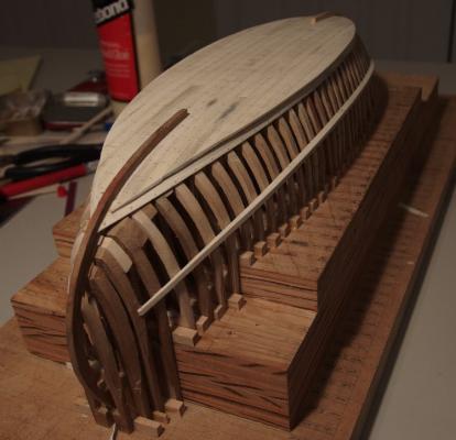
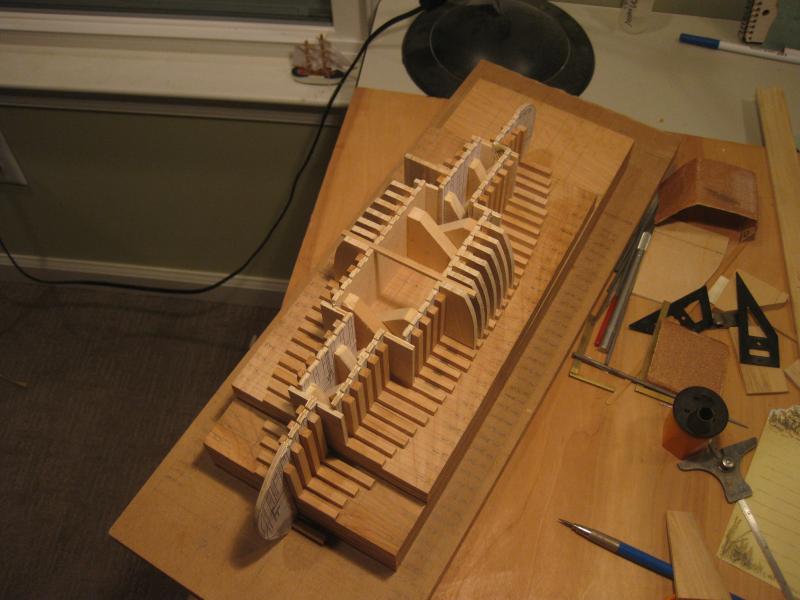
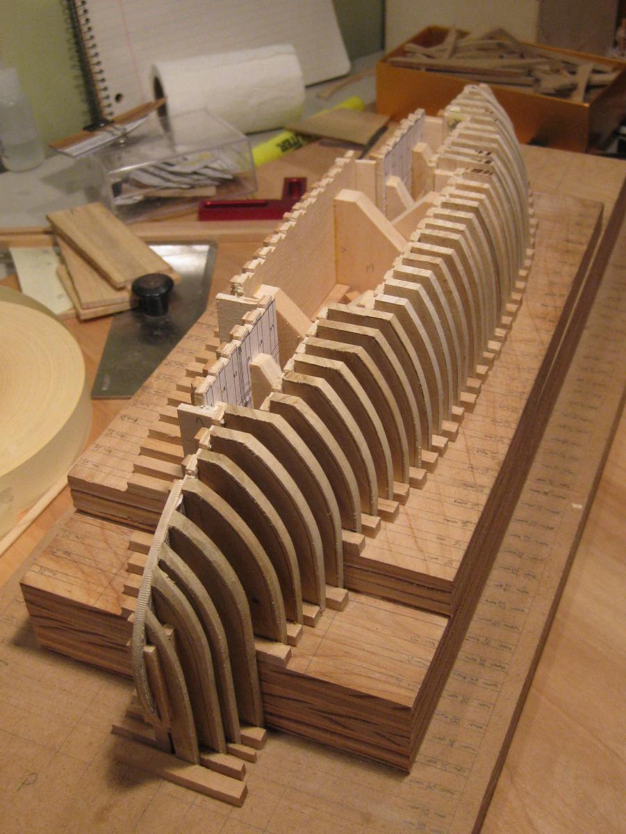
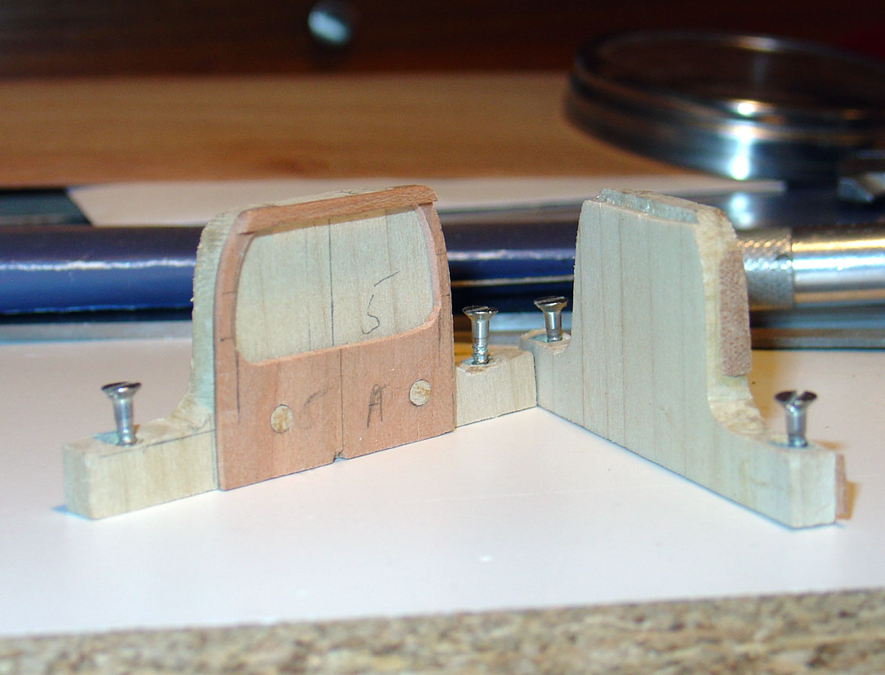
Culé Hull Construction
As with the chata, I was not confident in my templates, and resolved to do final shaping on the building board, remove the side fames, cut away the inside shape, and then attach the floors.
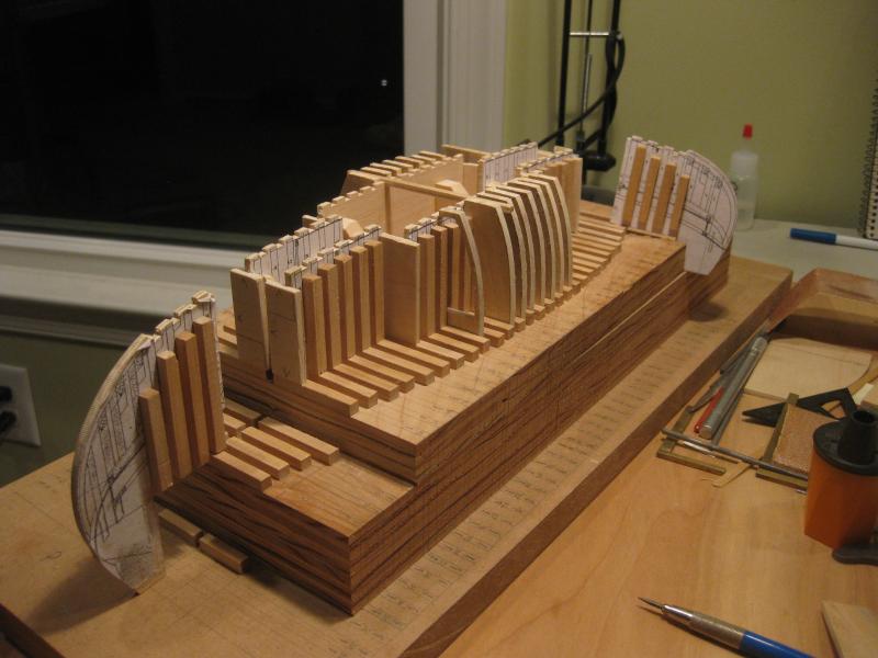
There is too much rocker to easily build it right-side up, and too much sheer to build it upsidedown on a flat board. So I created a wedding-cake (layered) board to add stability and minimize wasted material.
Given the larger scale, I did not need solid spacers and full-width blanks, as with the chata. So I created an interior framework, wider toward midship. The pieces at the ends needed to be removable so that they could be replaced with the stem and stern pieces. To the outside of the framework were added vertical and horizontal spaces to keep the individual side-frame blanks in place.


The blanks were a friction fit between the spacers. With humidity changes it was sometimes necessary to do a little sanding or add paper shims. When I made a mistake I was able to toss a side frame and replace it. This picture shows the side frames with the outer shaping mostly complete.

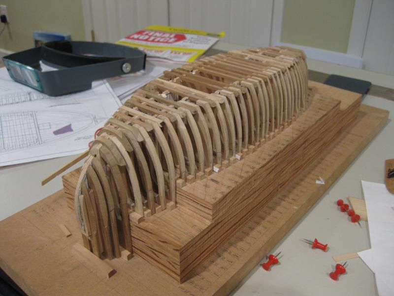
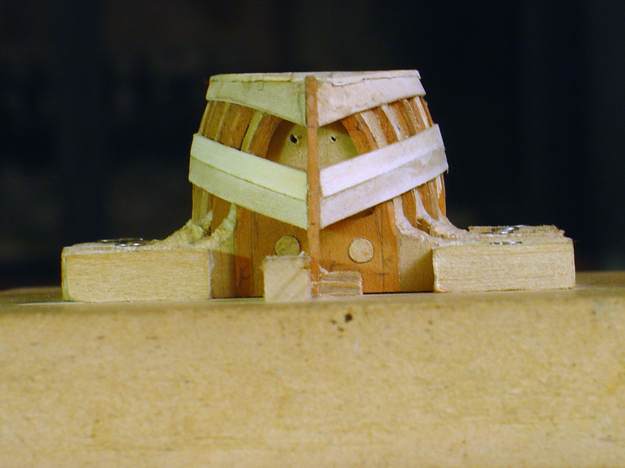
Once the outer shaping was done, I could cut the inside to shape and add the floors. Each entire frame assembly was removable, and I had to replace a few poorly done ones.

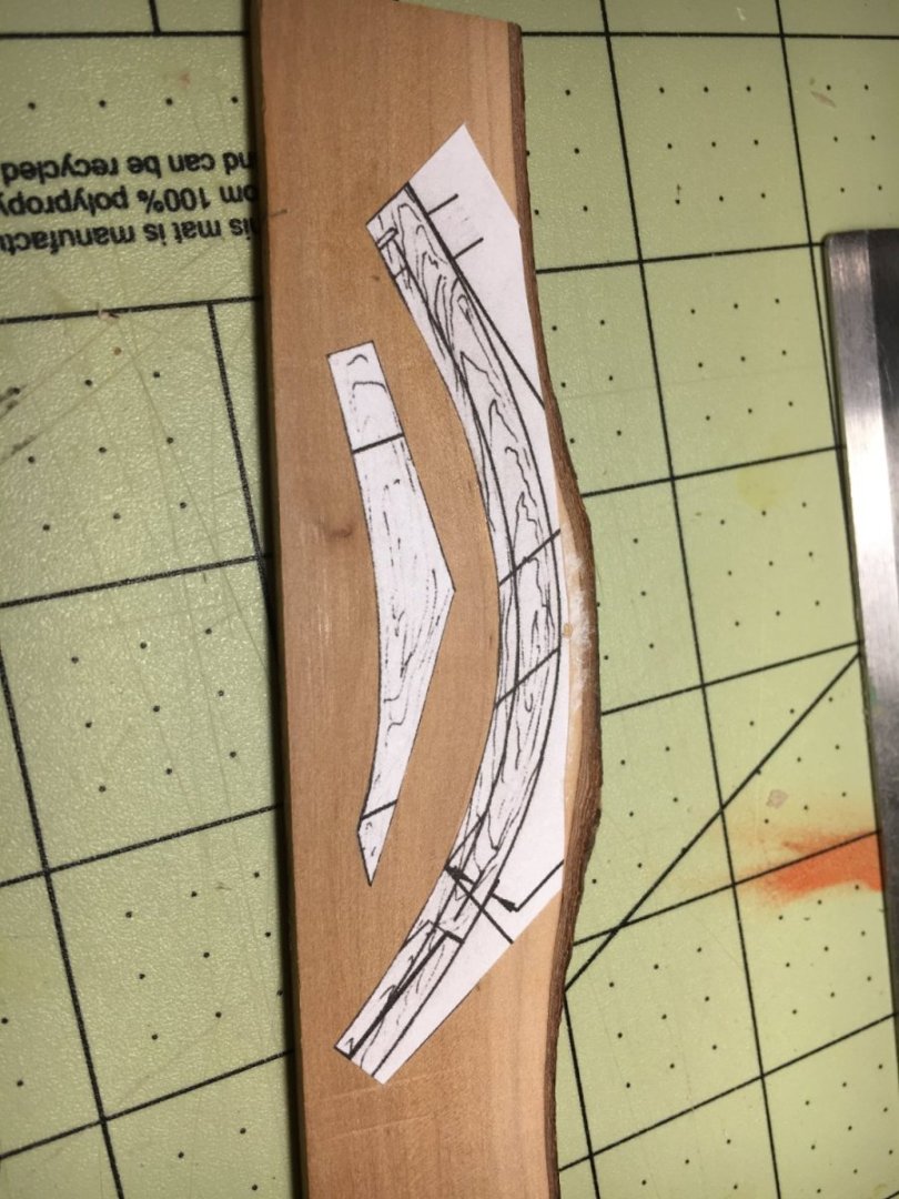
Here is a frame toward the bow being assembled.
And here is the planking underway.
More pictures and text can be found on my model club page for this build.
- qwerty2008, Tadeusz43, Michel and 7 others
-
10
-
Construction of the chata
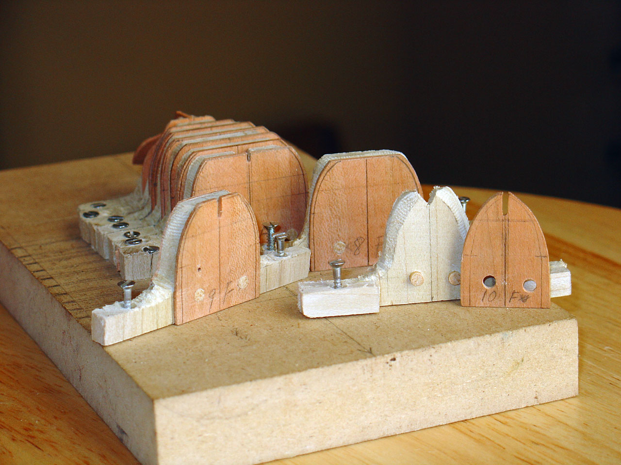
The ribs were created from 0.05" (1.25mm) blanks of cherry. I was not confident in the accuracy of the drawings nor the templates I created from them, so I planned to do final shaping after assembly on a building jig. This required the ability to remove the blanks after shaping so that the inside could be cut away.
Since there is no keel, temporary spacers held the frames in position and provided support while shaping the delicate pieces. The spacers could be removed, and pegs allowed each blank to be removed from its spacer, the inside cut to shape, and then returned to the same position.
Once all the frames and spacers were attached to the building board, the stem and stern pieces were added (being necessary to properly fair the frames).
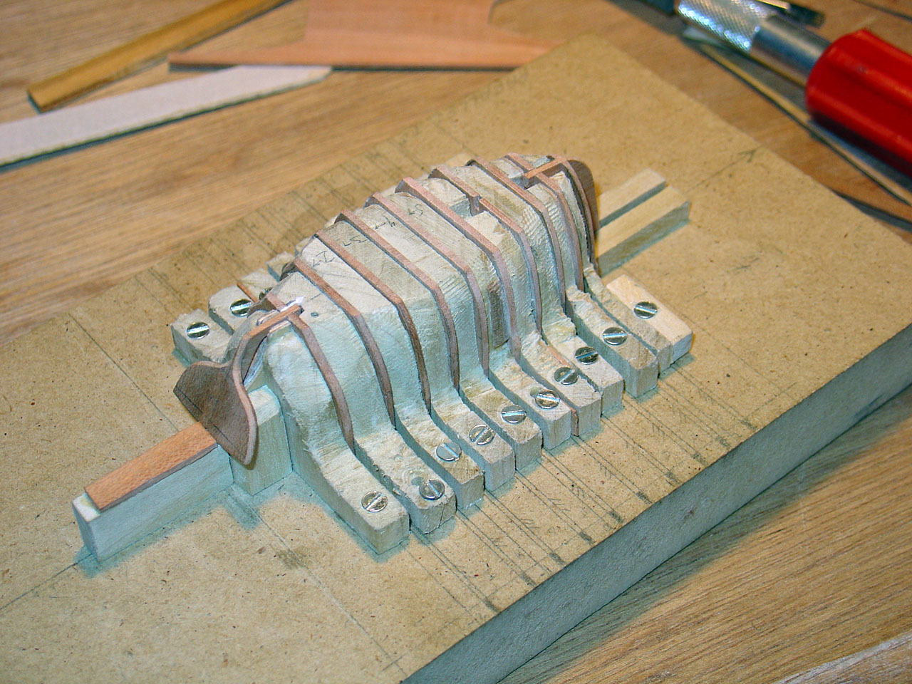
The inside cut creates separate port and starboard side-frames. These are connected by a floor lapped to the side of the frame closest to centerline. Once the floors were added, the frame assemblies and spacers (now notched for the floors) were reattached to the building board.
Side and bottom planking underway, and complete. The planks are 0.02" (.5mm) holly.
Interior details being added
More pictures and text can be found on my model club page for this build.


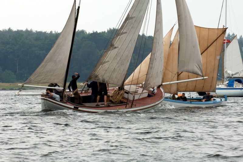
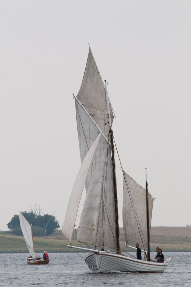


De 13 Søskende 1911 (The 13 Siblings) by gkharrin - Scale 1:24 - Danish fishing smack
in - Build logs for subjects built 1901 - Present Day
Posted
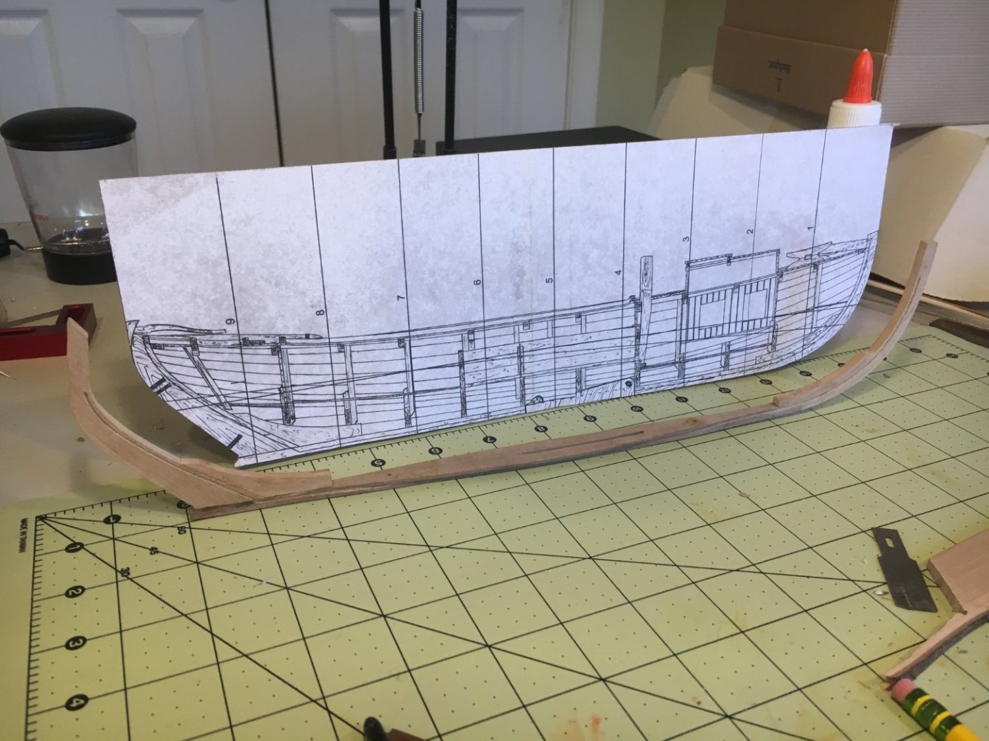
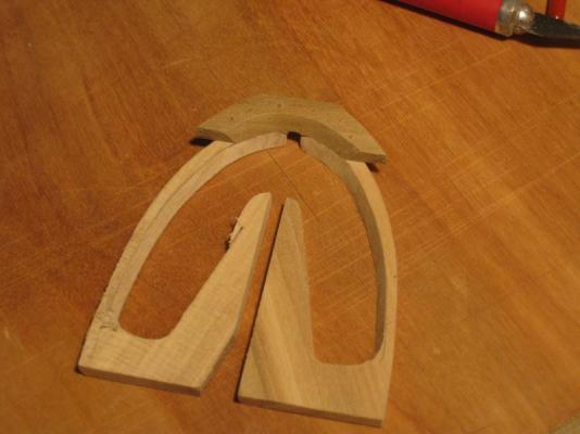
The building jig
Transferring shape of stern from port to starboard