

paul carruthers
-
Posts
129 -
Joined
-
Last visited
Content Type
Profiles
Forums
Gallery
Events
Posts posted by paul carruthers
-
-
-
-
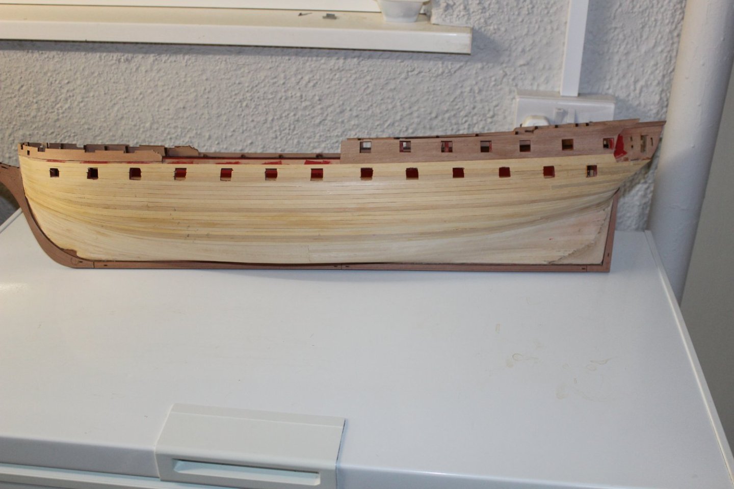
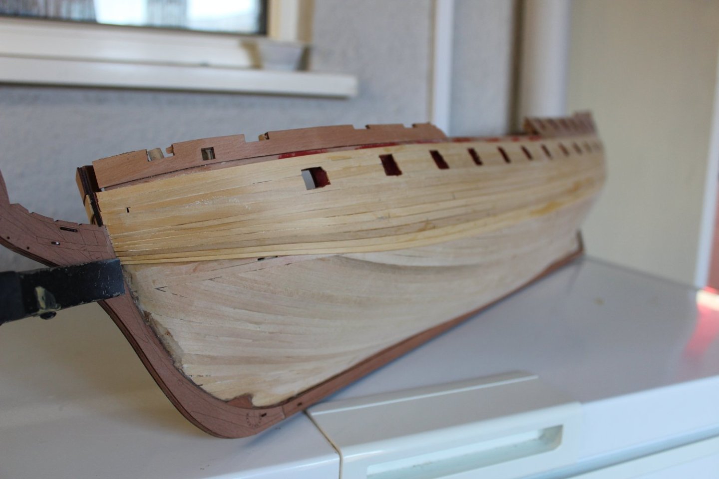
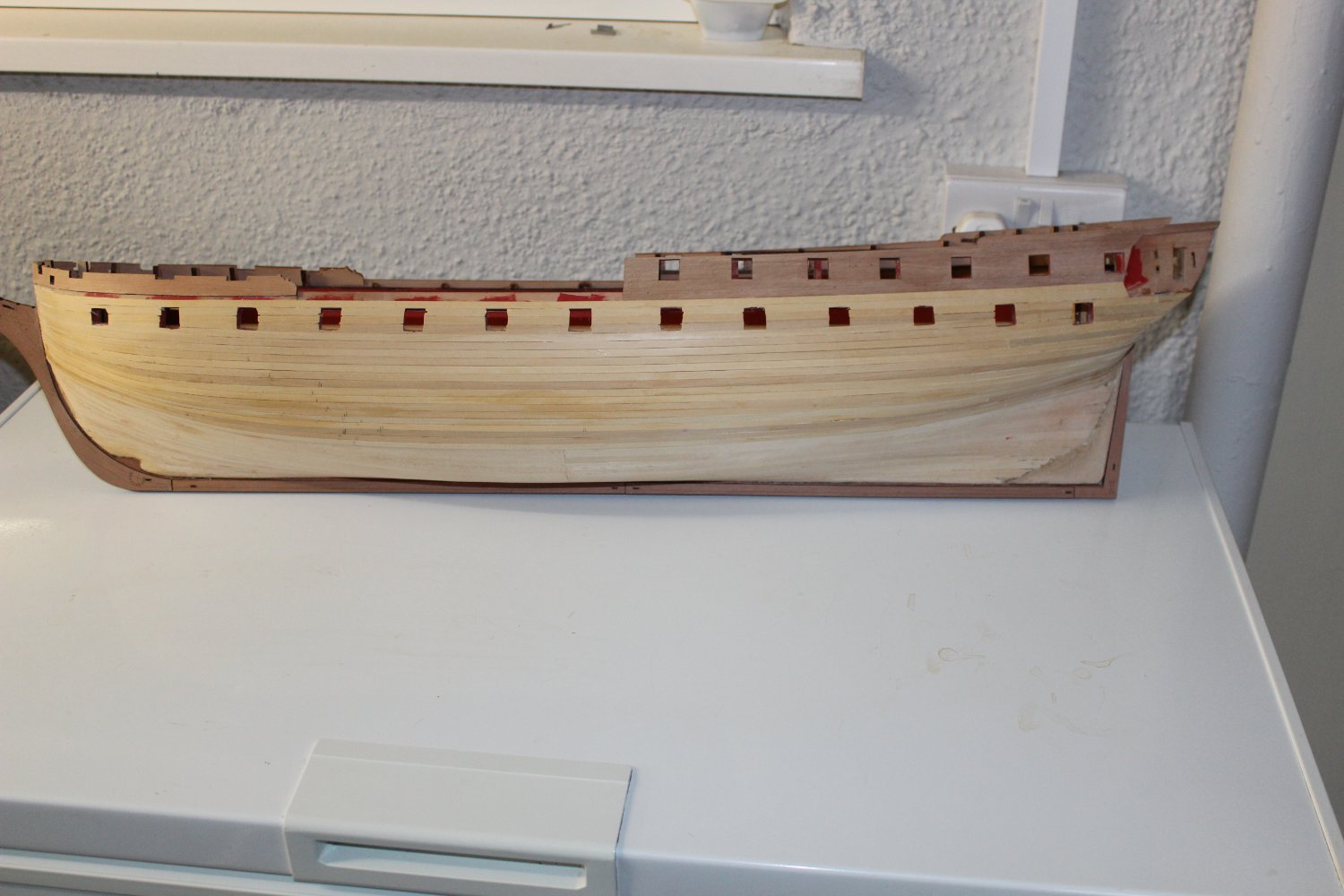
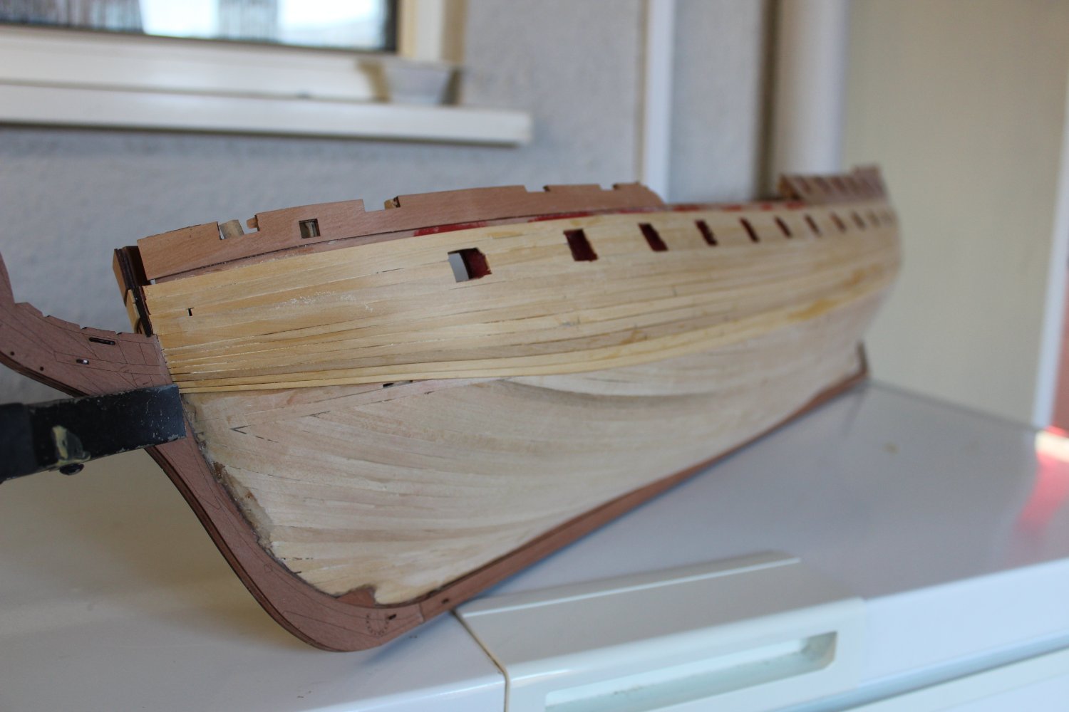
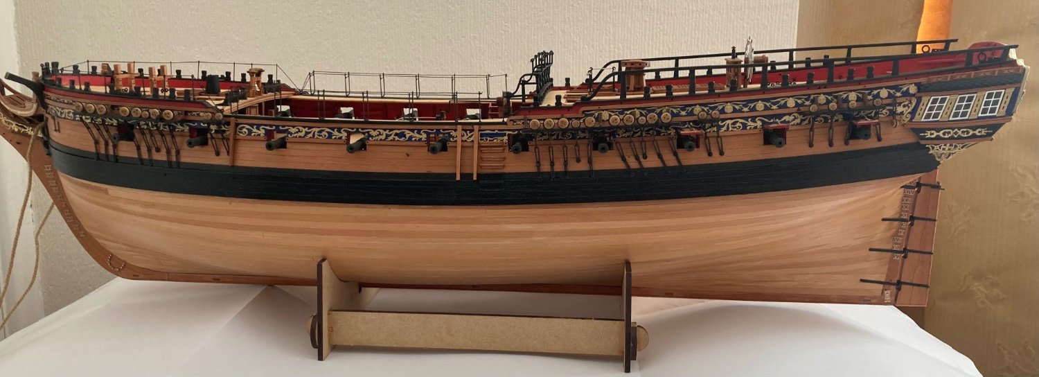
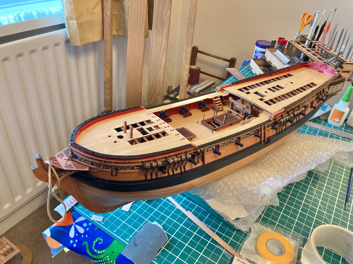
After all that planking I couldn’t bring myself to paint it lol.
- Old Collingwood, mtaylor, davyboy and 1 other
-
 4
4
-
16 hours ago, Kevin said:
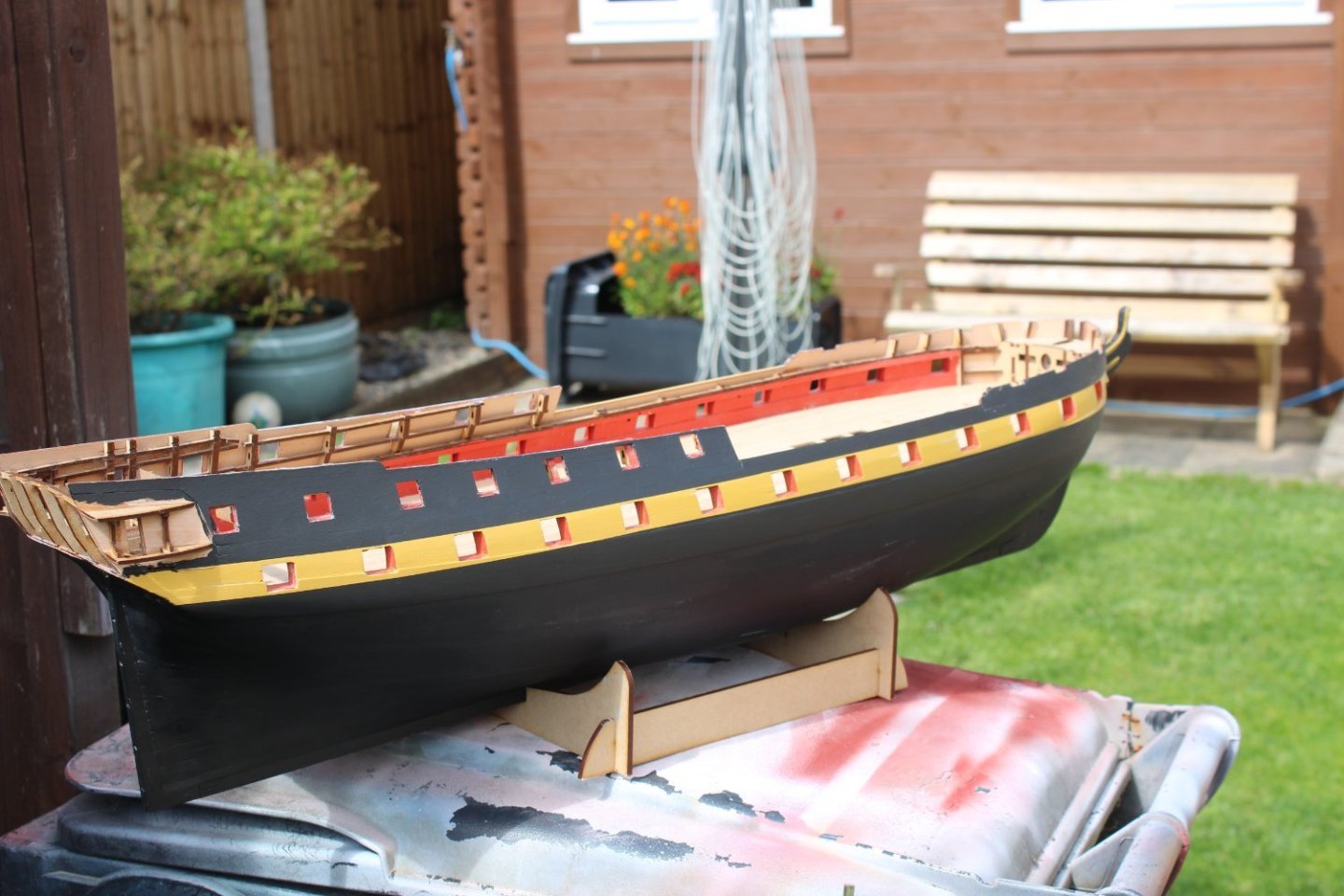
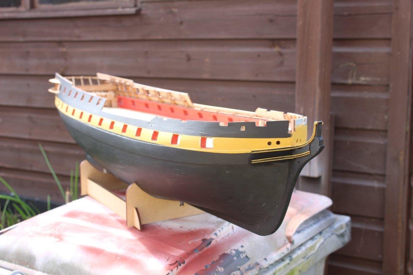
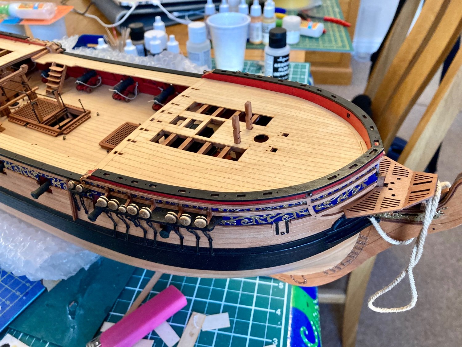
one side in the correct colours,, although more coats are required, also the banding has gone a bit narrow at the bow above the cheeks, to be sorted
-
If you have to enlarge the hole use a band of cartridge paper to hide the gap, it’s all painted black and will not be seen
- mtaylor and aydingocer
-
2
-
I used a mini iron, the type used for covering model aircraft, I lightly wet the planks as per Chuck’s lateral bending method but I bent the planks into shape on the hull’s primary planking and held them in place with the iron, it gave a good result.
I found chamfering the rear top of the planks essential to a tight fit. -
21 hours ago, Kevin said:
good afternoon everyone
my build has somewhat ground to a halt for a while, my mum has been admitted into hospital having had a mild heart attack, and now has failed a Covid 19 test,
here are the latest photo's taken
 On 4/4/2023 at 5:34 PM, Kevin said:
No Glenn, i hope it will be better

It’s worth the effort in the long run.


-
What hides the dark centreline where the etched deck is joined?
- mtaylor and Old Collingwood
-
2
-
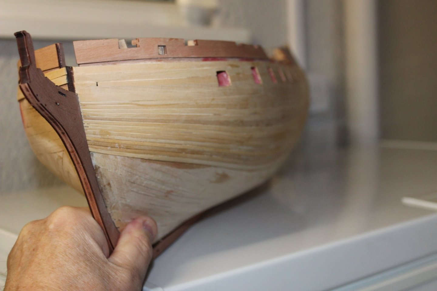
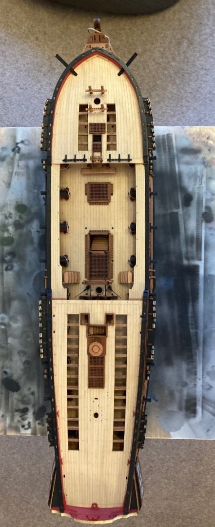
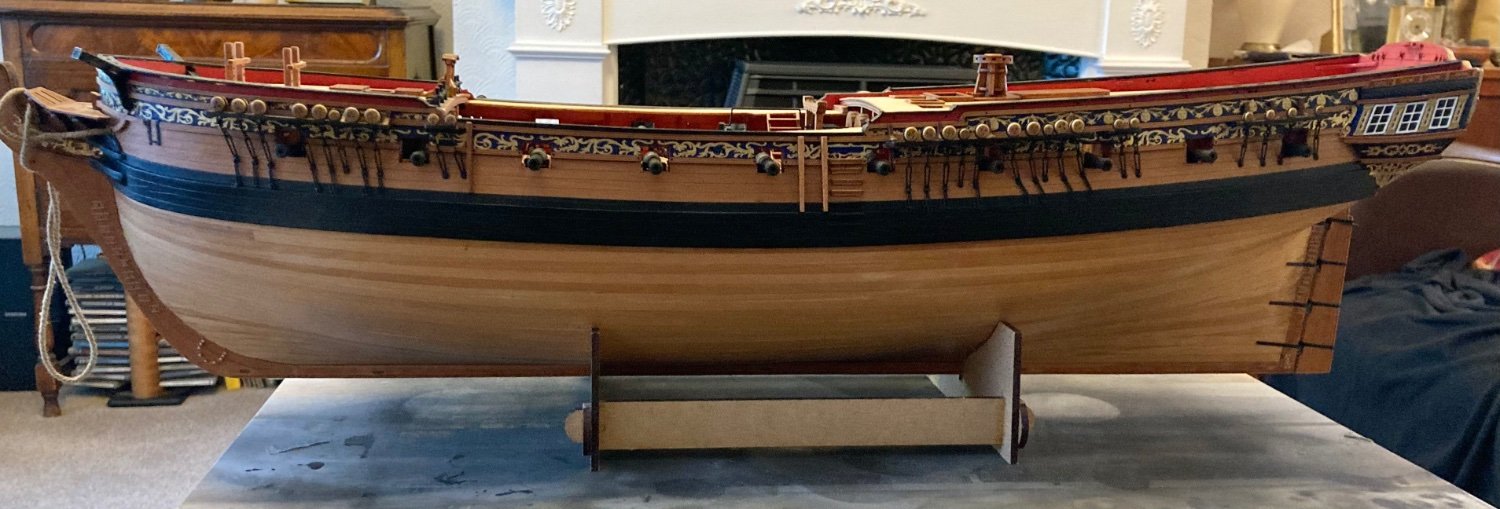
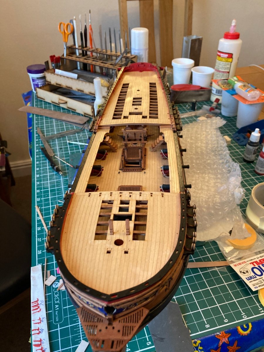
Thanks, gives a real image of the size.
- mtaylor, thibaultron and Dave_E
-
3
-
James, can you include a few shots of the full hull with your hand adjacent for size comparison, thanks.
- thibaultron, mtaylor and Dave_E
-
3
-
If you divide cost by build time it’s not a huge amount of money, compare to golf club membership etc.
- mtaylor, BobG, thibaultron and 5 others
-
8
-
-
-
-
3 hours ago, Blue Ensign said:
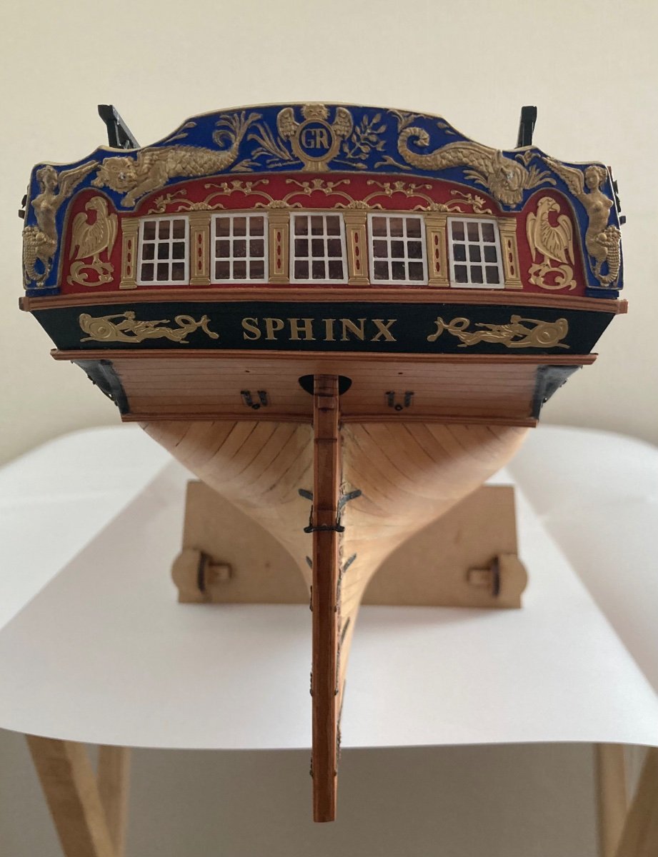
That bow shot of the headworks looks good, and I like the white paint scheme of the wheel. 👍
As far as the masting is concerned, if you have a variable speed drill you can use it as a proxy lathe and hand sand any taper required, or if you're using square stock the razor plane can be used to gradually round the stick, finished off by hand sanding.
I don't imagine the lower masts will be too problematic because little if any taper is required, maybe some flattening for the cheeks. The tricky part will be keeping the masthead which is square in section true.
Were I doing it, I would cut around the base of the head using a razor saw 1mm deep, glue a template of the square section on top of the dowel. Pare it down by degrees using a chisel or similar, and finish with sanding sticks, constantly checking the square.
The Topmasts are more tricky, having an octagonal heel, square head, and flared hounds. On these I would personally start with square stock, as the rounding and tapering are easier to do, but if you're using round stock then a sharp chisel will be your friend. I would mark off each section using Tamiya tape, and begin with the rounding and tapering section between the heel and hounds.
B.E.
Thanks for that, I guess slow and measure is the best way as you recommend
-
-
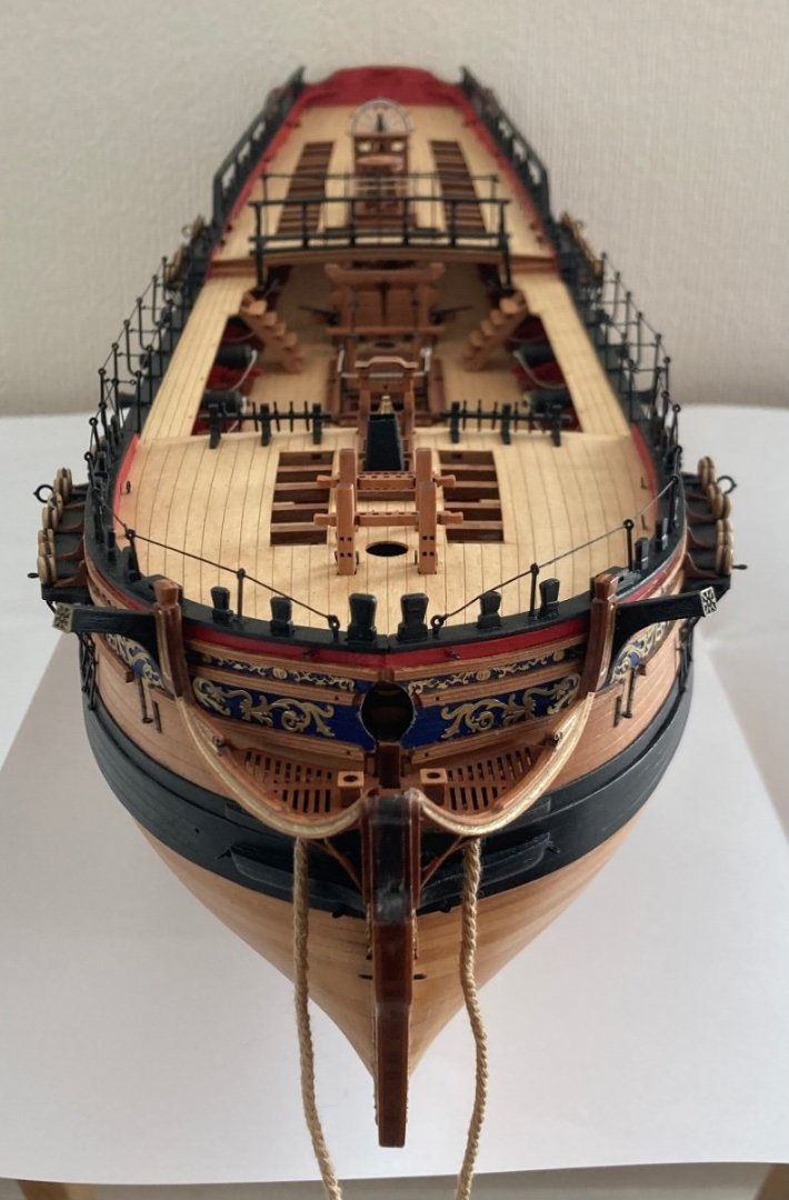
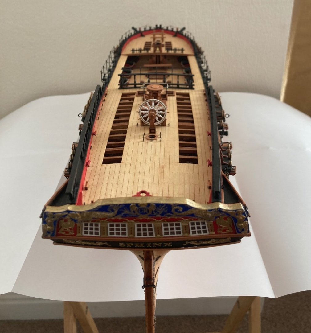
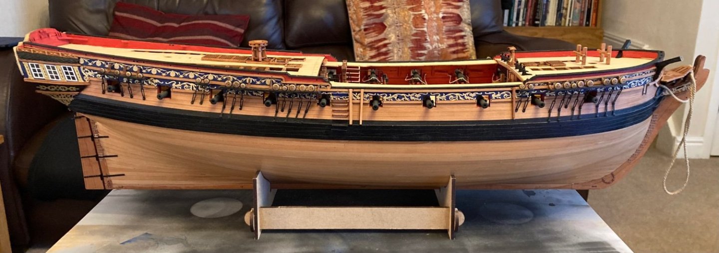
Update, ready to commence the small craft, look challenging.


- Gregory, chris watton, Cirdan and 13 others
-
16
-
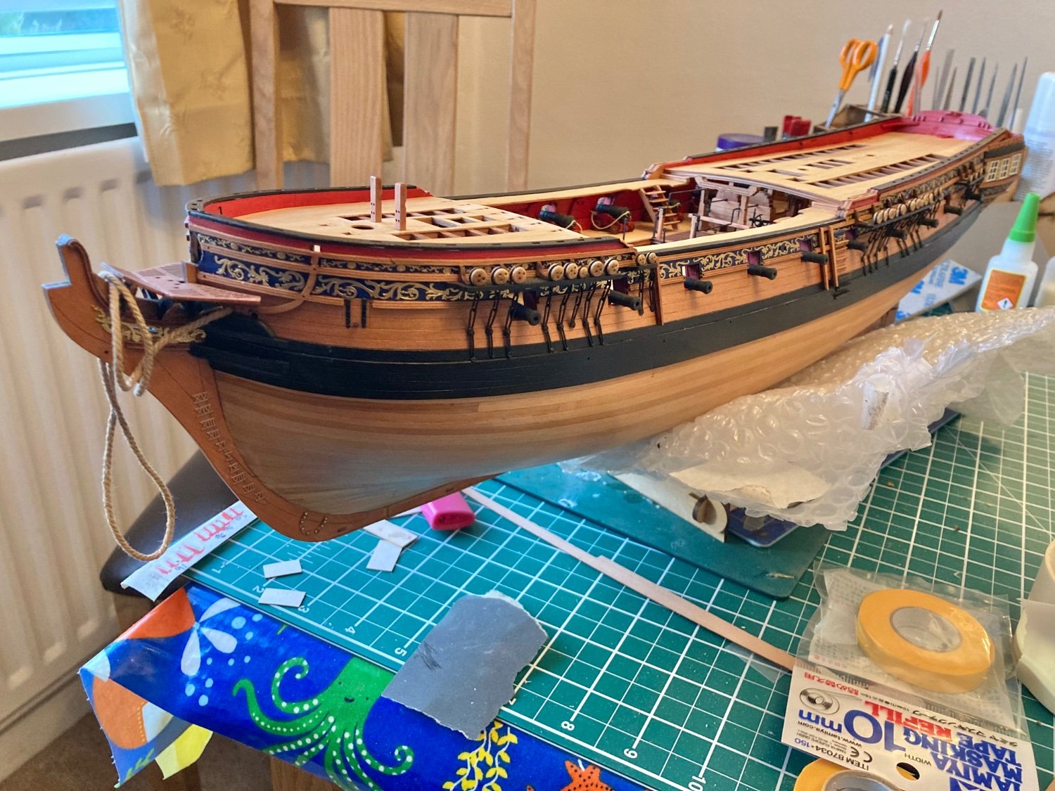
Beautiful build, well done.
-
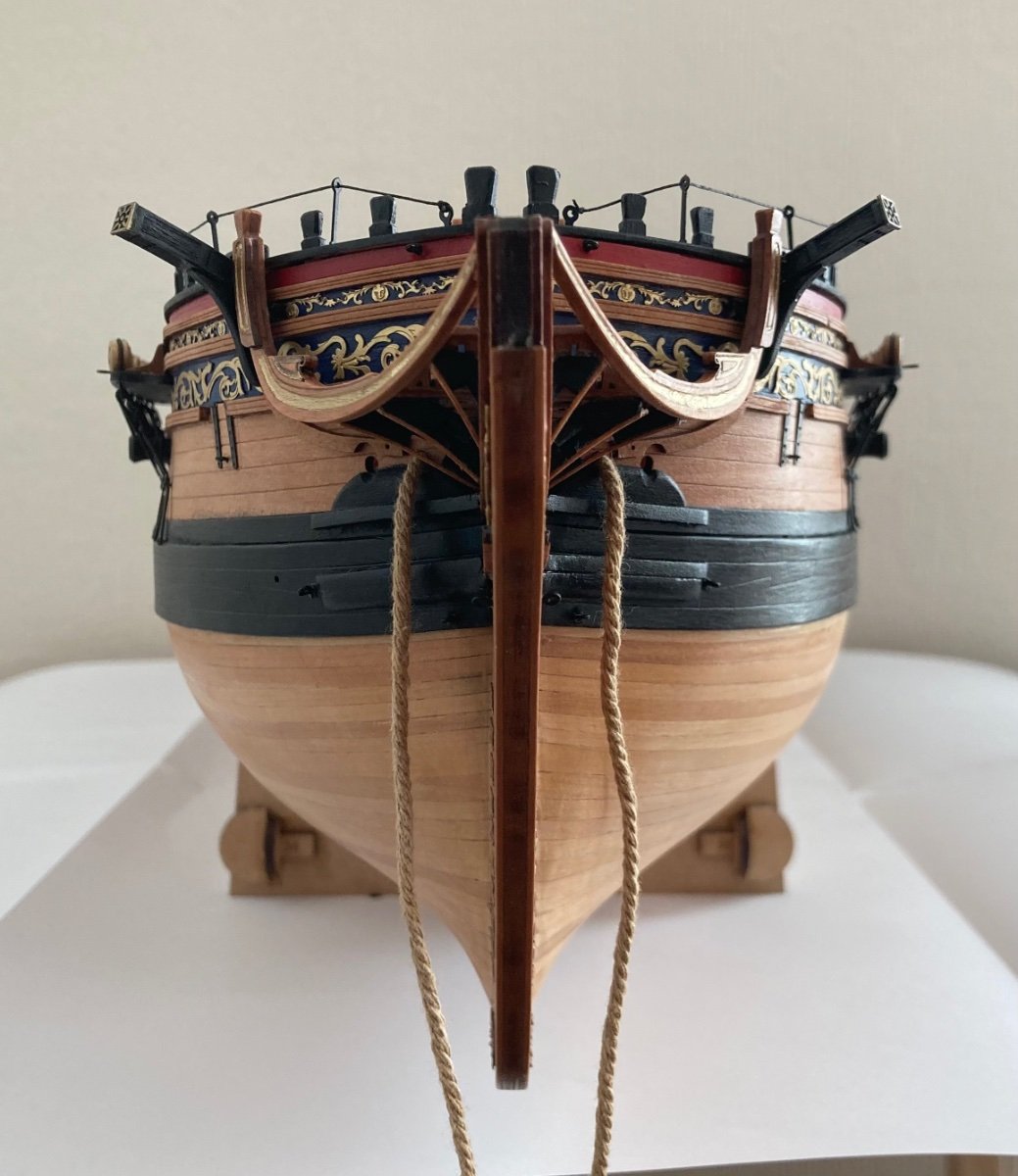
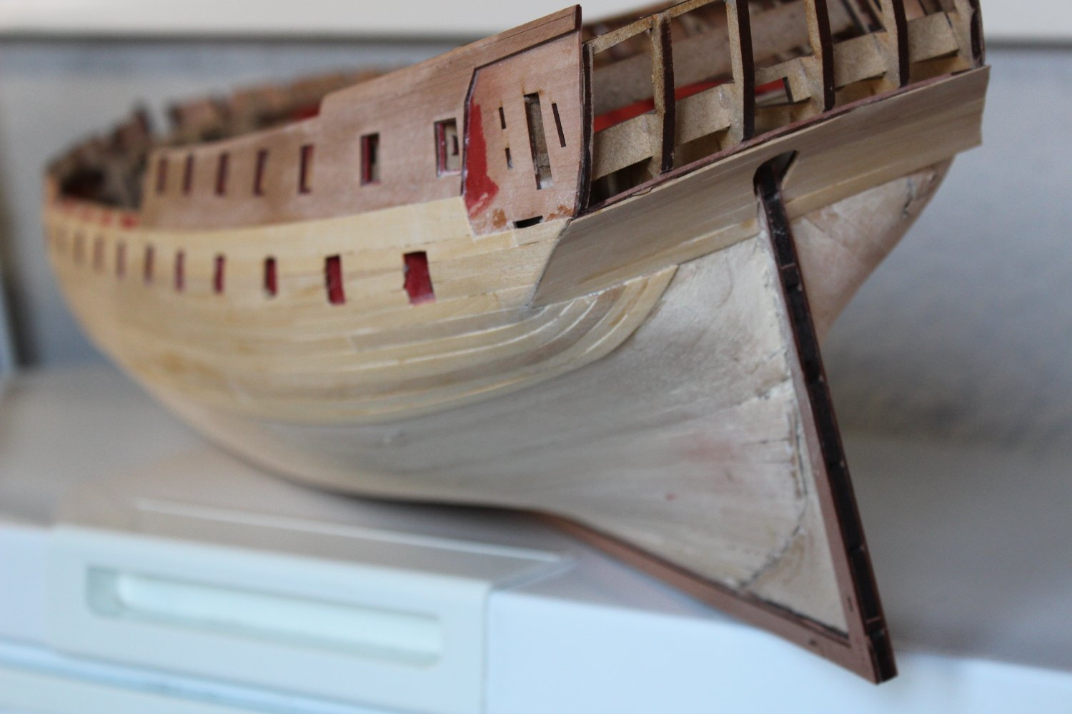
Time for a break, my rudder gap is too large but I’ve not the courage to try and remedy at this point.


- Theodosius, hollowneck, bruce d and 9 others
-
12
-
1 hour ago, Blue Ensign said:
Thank you Nipper, Bob, and Kirby.
Post Seventy- nine
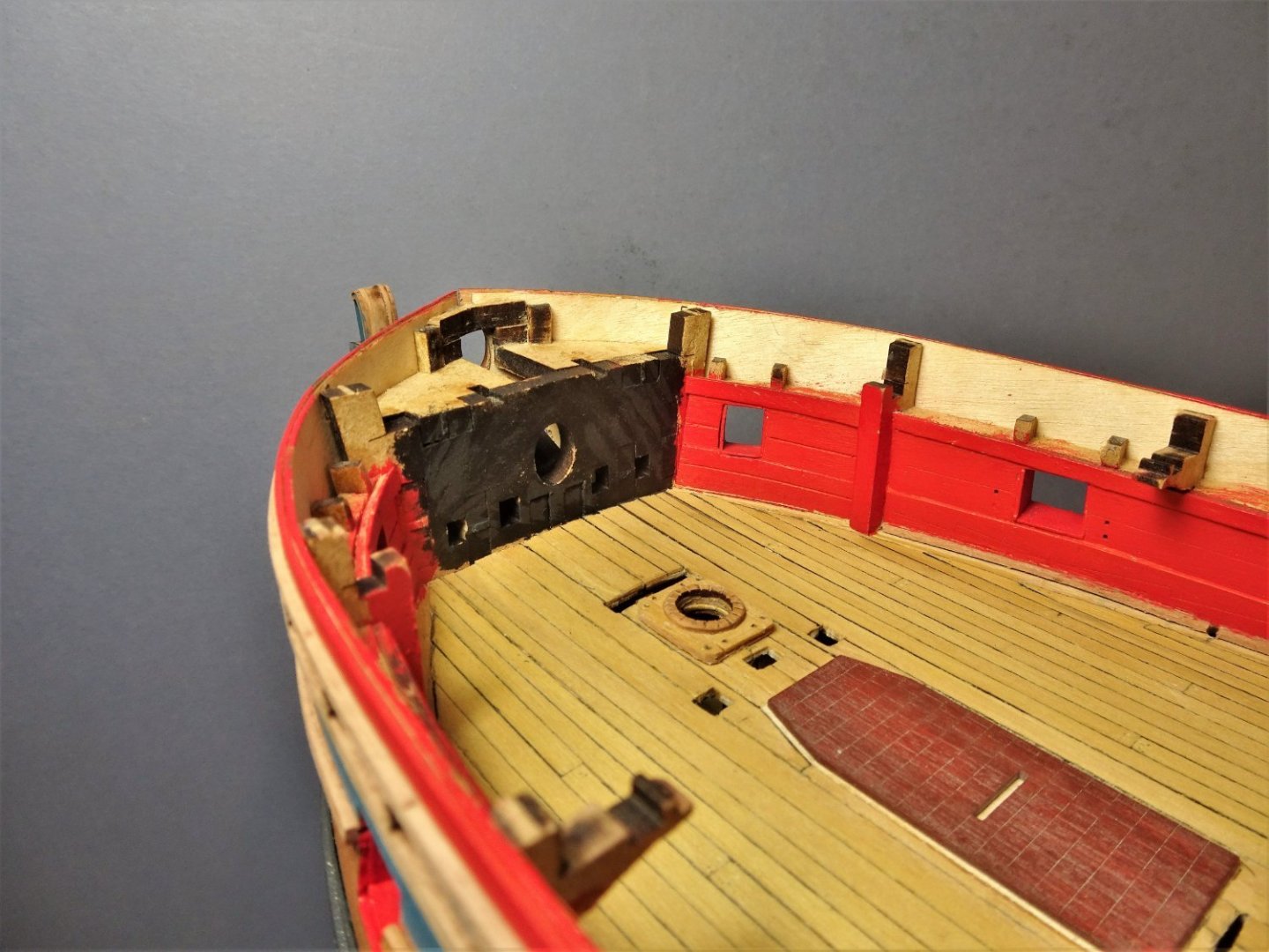
Fiddling in the Foc’sle
The forward end of the internal bow area can’t be authentically represented as it is cut off by the kit bulkhead, a simplification of the kit design.
5647
This is painted black with areas of shading to hopefully give the impression of shadow in any view that may become apparent.
The Foc’sle deck will also need to have sufficient planking to mask this area from view.
This shot of the wonderful Winnie build by Rusty shows how the very forward end of the Bow should look.
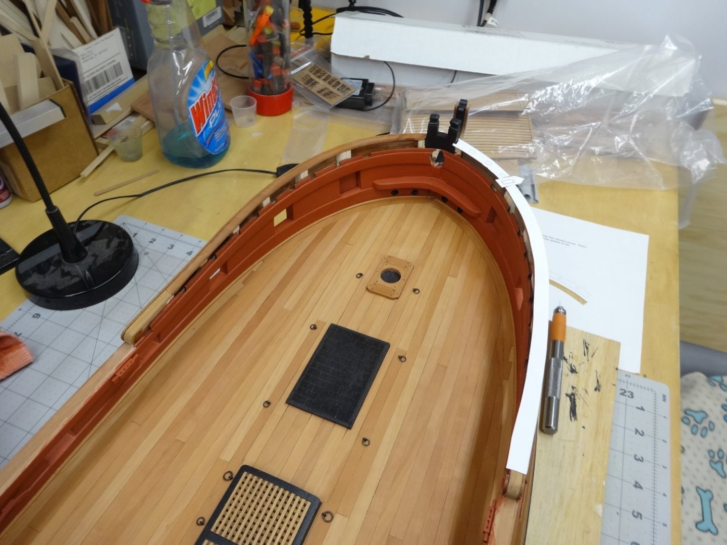
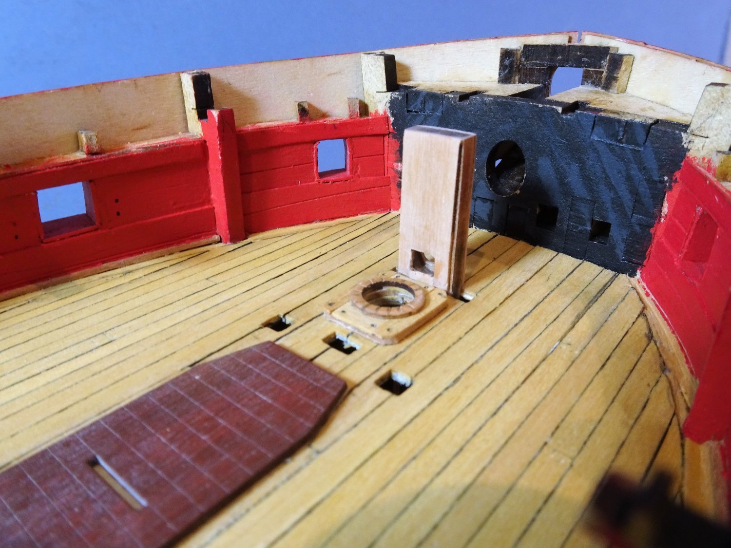
I have gone as far as I can with the basic modification by opening up the Bridle port and planking the internal area otherwise left unfinished.
One other practical modification is the addition of manger boards running from the Bridle port to the Bowsprit stop.
Creation of these has to be done in conjunction with the Bowsprit stop, and the Fore Topsail sheet Bitts against which they fix.
The Bowsprit also has to be considered in fitting the Bowsprit stop.
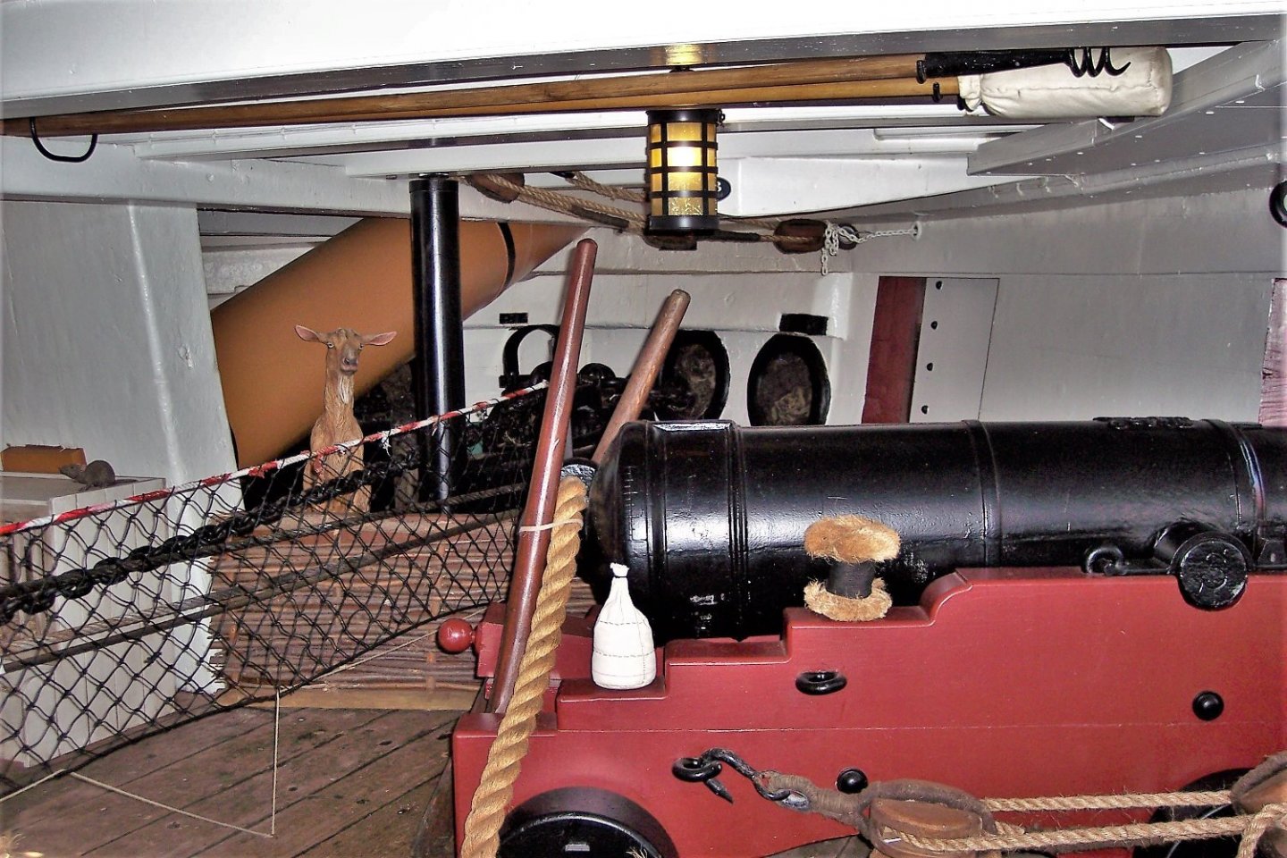
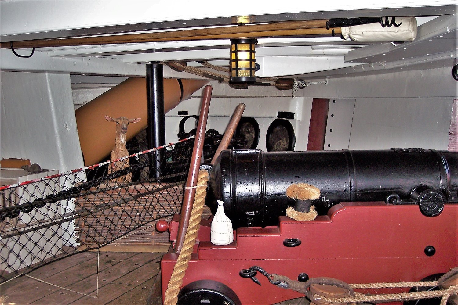
123
This shot of Trincomalee demonstrates the arrangement. The low manger boards can be seen (complete with curious goat) and the square tenon of the Bowsprit.
Also of interest is the tackle for the Bridle port lid running beneath the deck beams.
In the kit the arrangement the stop is simplified with a hole into which the Bowsprit fits.

5648
The stop is faced with some 0.8mm pear and the tenon mortise cut.
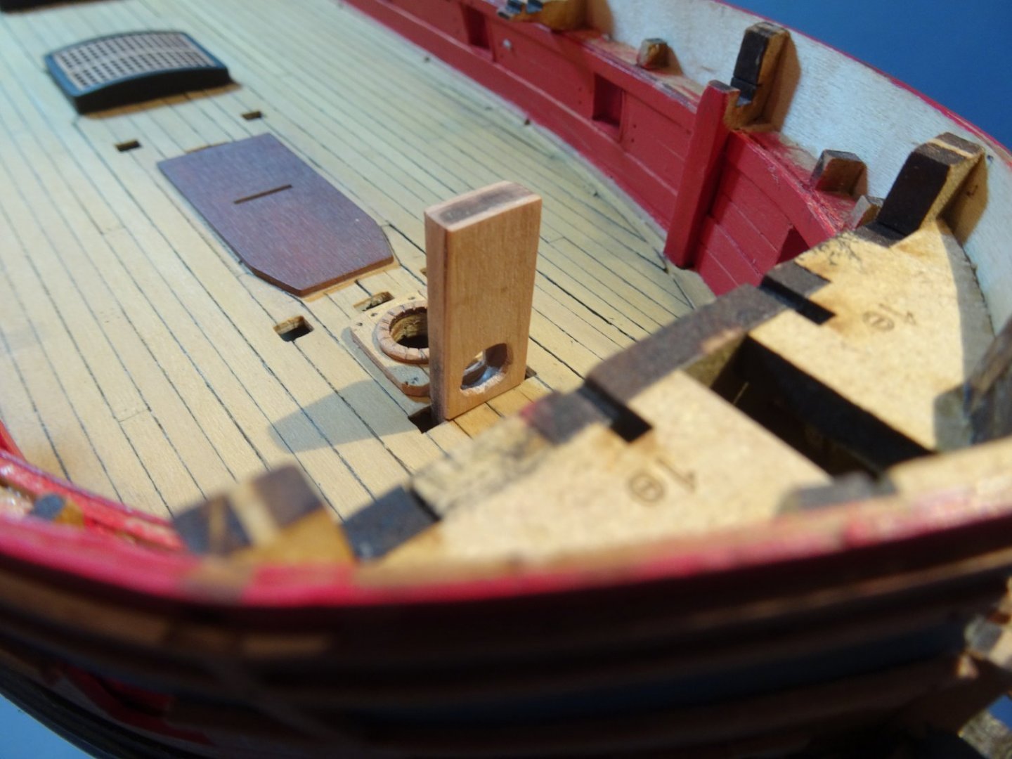
5649
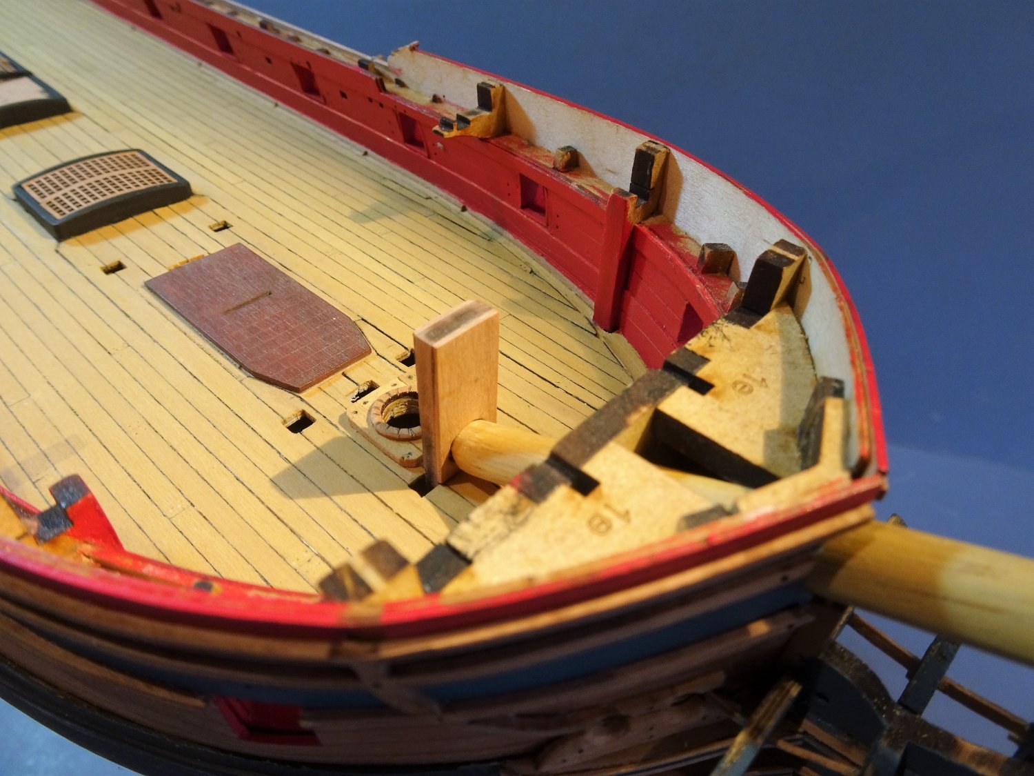
At the forward end the hole is adjusted to take the Bowsprit.
This is also a simplification as the tenon mortice only should run thro’ the stop, but the effect should look the same.
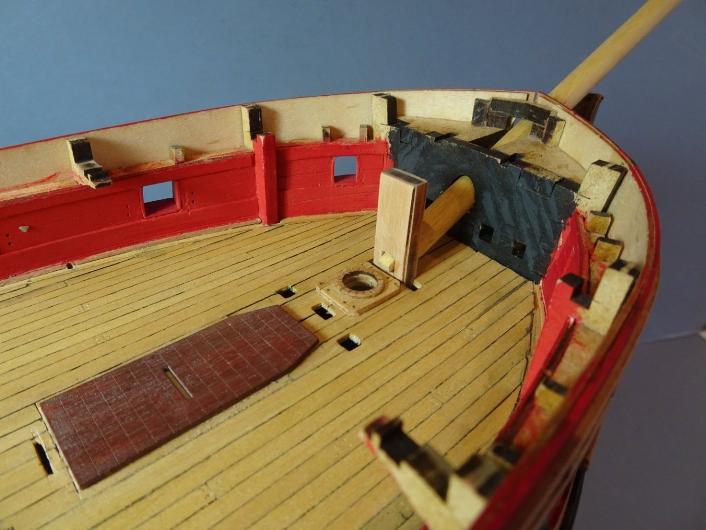
5651
The tenon in the heel of the Bowsprit slots into the stop.
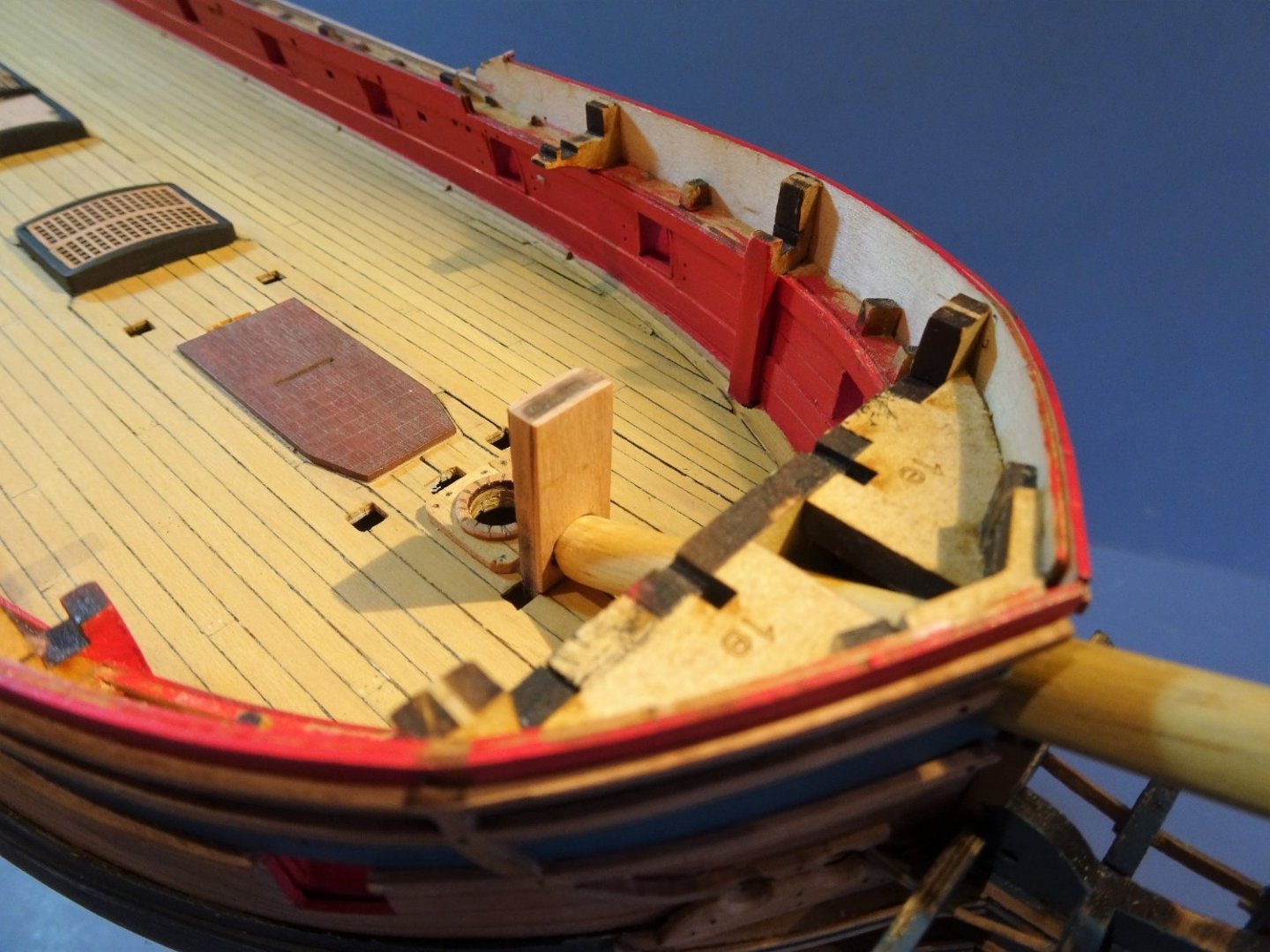
5654
From forward.
.thumb.JPG.ab2deda4d3cd22bd7e5357f9daca241c.JPG)
5652(2)
I ensure that the Bowsprit slides smoothly into place with the minimum of effort.
This will be visible thro’ the un-planked beams.
In my next post I will be looking at Manger Boards.
B.E.
12/02/22
Great model build, You’ve probably thought of this but I’d sort the cat heads now, I’ve limited experience and I’m following the manual, which is great but I found fitting them as per the manual difficult
- mtaylor and Blue Ensign
-
2
-
Thanks to everyone for the positive feedback, people are well aware that we are usually very critical of our own work and all the thumbs and comments are really appreciated.
- chris watton and mtaylor
-
2
-
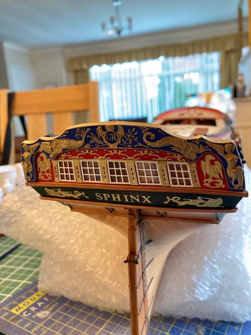
A little more progress, a bit of fettling to get a good fit on the gunwales, and I’ve no idea why some pics are upside down


- bruce d, GrandpaPhil, hollowneck and 10 others
-
13
-
-


.JPG.a64293ae1a3e6e80c431bc405ca6da25.JPG)

HMS Indefatigable 1794 by Glenn-UK - Vanguard Models - 1:64
in - Kit build logs for subjects built from 1751 - 1800
Posted
Yes but the loss in flexibility is not an issue