


popeye the sailor
-
Posts
15,981 -
Joined
-
Last visited
Content Type
Profiles
Forums
Gallery
Events
Posts posted by popeye the sailor
-
-
-
superb model Chris..........well done! great job on the wings.........must have been hard to get them to line so well. all around beautiful model!
")
-
sweet that a dio base was included...........I usually make my own, but they lack the detail you'll see with yours
")
- Edwardkenway, Canute, Dave_E and 5 others
-
 8
8
-
you made my eyes go big when I saw this! just so happens that I received two SU 27 Flackers @ 1:72 scale, along with a Rafale A @ 1:72 scale a couple of weeks ago. they were on the Old model kits site for so long, and I wondered what was wrong with them..........I'm not a Jet guy, but they looked so lonely
 they came in the same box {wondered what that was all about}......haven't taken the time to check them out yet, but they are Revell and the price was right.
keen to see your progress
- CDW, Egilman, Edwardkenway and 5 others
-
8
-
according to the instructions....... the Revell color chart suggests a dark gray. I think the Special Hobby instructions suggest the same..........I shall refer to my translator. I just looked at the translator I downloaded........seems I got my grau and grun mixed up
 I can change it.........that Monogram paint looks more like a stain, than anything else. it's nature suggests that it would be more suited for wood.
likely 55 to 60 degrees........any more than that, I don't think even dive brakes will keep you from creating a crater
...........not only that, the bomb is supposed to get there before you do. jets have more thrust, but I think wing shape is important too. I learned quite a bit during my initial stint with balsa airplanes....lucky to remember 1/4 of it today.
I've done that before Jav.......never got the success that others got. did you have a cello canopy? this is the first model I've done that supplies one. I set it in the living room window..........it's worth a try
-
the procedure is to insert a wire in the vein at the knee, until they get it to the inner thigh. they numb it while they are doing this....can't say that it is totally painless though. once the wire is in position {it has a heating element at the business end}, it is heated to cauterize and close the vein. I was awake during the procedure.......pretty much joked the whole time
the guy at the computer that was tracking the wire........the computer made this cool rhythmic sound.........I told him that if I had my bass with me, I'd give him a run for his money! I have the compression socks too, but I don't wear them all the time........just doesn't look cool with a pair of shorts
do you have the discoloration in the calf area?....I have it more on my left leg. yes.......sitting is not good.........I tend to stand quite a bit when I model now. don't let it rule you.......let your passion flow!
 me 'n Gibbs go out for our walks........took 'em on a good one this morning....this time HE was tired! I wish you well as well my friend...........really though......even if you can stand there for just a short time........try to continue modeling. I'll bet it will make you happy
 Be Excellent!
just a short that I haven't forgotten this one........I'm painting the glass. it's a pain in the ash........the detail doesn't want to be my friend. I am putting on some of the odds and ends though, so that's cool {sorry....saw the movie, and now everything's this 'valley girl' type junk now {it'll wear off soon} {I hope}. wasn't a bad movie.......they had a character named Denis
-
hello Ed.....your just in time
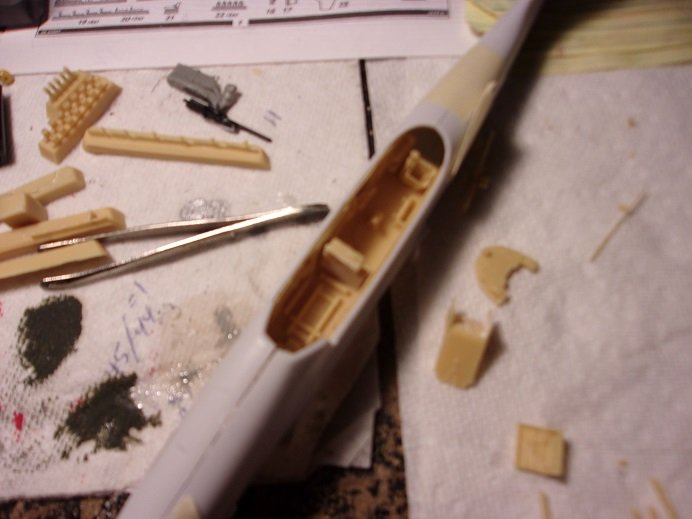
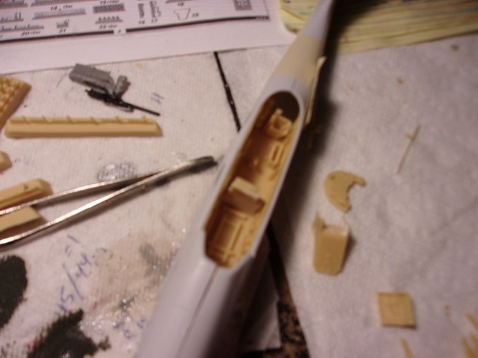
I felt I had enough pictures together to make a decent report....they pick up from last Friday. firstly........I was able to capture a decent picture of the cockpit. with everything in place, it will be pretty detailed.........odd thing is that a few of the parts are not in the kit. they need to be scratch built {simple stuff, but effective}.
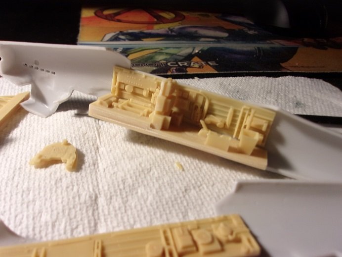
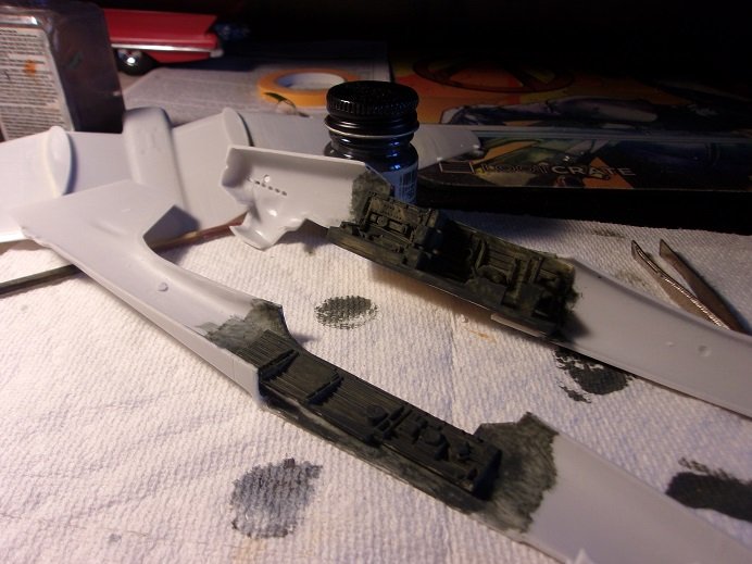
as can be seen, I did what I suggested........the floor is cemented into one side of the fuselage. this particular side has a couple brace bars that connect the gun post to the wall, so this was already predetermined. I'm not happy with the idea that it requires a dark paint. Schwarzgrun, which according to my translator, is a dark green....I have some that is made by Monogram / Humbrol {part of the paint booty}. I've been mixing the heck out of this stuff because it was separated so badly.......the pigment was a hard layer on the bottom

at a latter time, I decide to try and cut out the cockpit glass. for some unforeseen reason, there were two in the kit.........like the cost of failure was so high. the first one didn't come out to bad.......only encountered one episode where it cracked as I was cutting it. it was very tiny, and I was able to smooth it over....cement will do the rest. in the rear, there is the gun opening.........a bit of a nail biter, but it trimmed out OK. the second one came out worse......the gun opening killed it. picture not that great......I'll try and get a better one.
I had my doubts about this paint. may cover better with two coats....
I'll see how it goes, but I don't want to put too thick of a coat on it. I finished fitting the tires in the boots......time to give them some paint. still need to paint the tires.
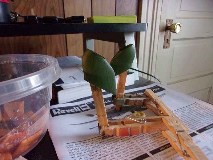
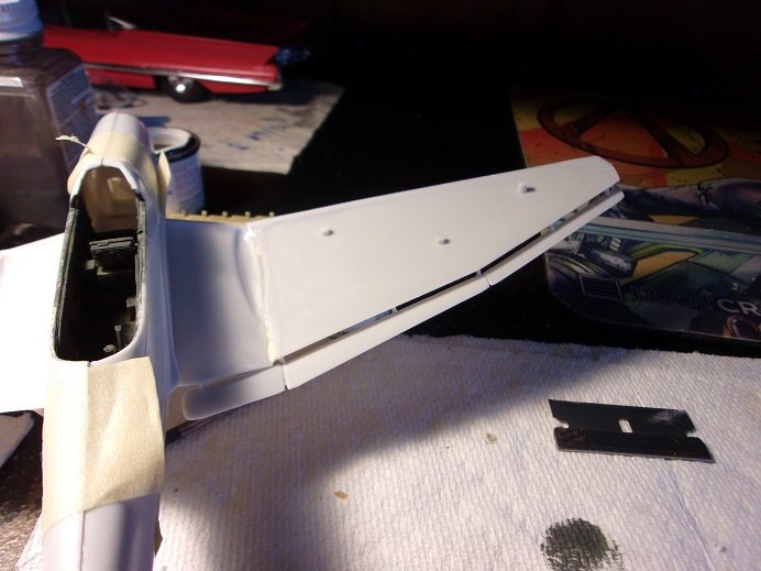
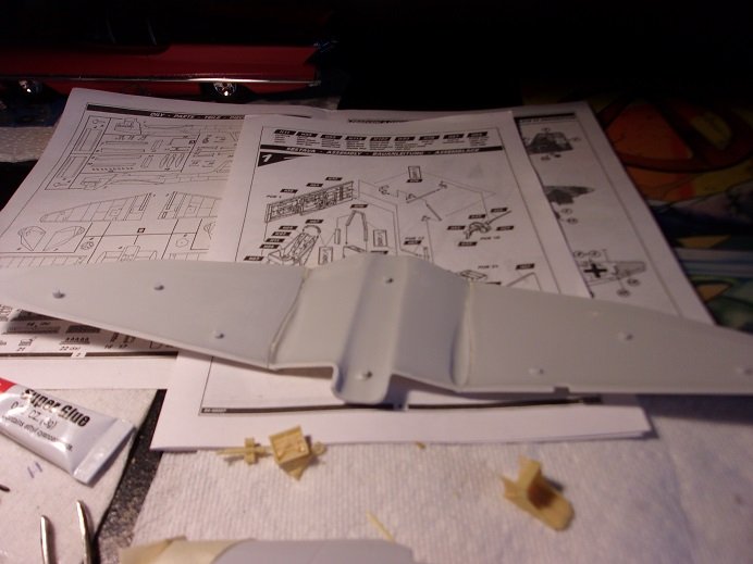
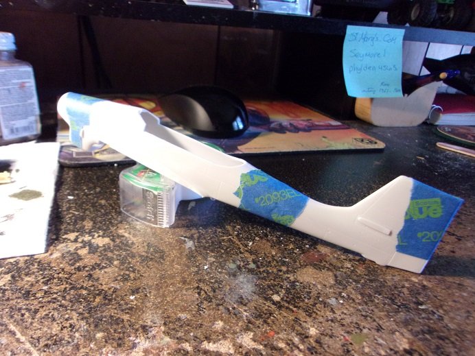
the fuselage was re dry fitted and the wing bottom was added. before I did that though, the brackets for the aileron flaps were added to the trailing edges of the wing. the ailerons on most planes are cut into the wing and lend to a more controlled dive and lift. the ailerons on the Stuka however, are set up apart from the wing surface, to allow a more aggressive dive. one problem with this, is that it is much harder to recover from such a dive as quickly. for that, the use of dive brakes are use to slow the speed of the dive, so the ailerons can function more effectively. I've noticed that on some kits, dive brakes are not included....the Revell kit doesn't have them, and neither did the Fujimi kit. the ones in this kit are resin parts and there was some trouble cutting them free. I may try my hand at scratch making a pair..........if I do well, I may make a pair for the Revell kit too
six tabs are cemented along the wing........when dry, they were lightly sanded to even them up.
your getting this in real time now..........this part I've been doing while chatting with you all
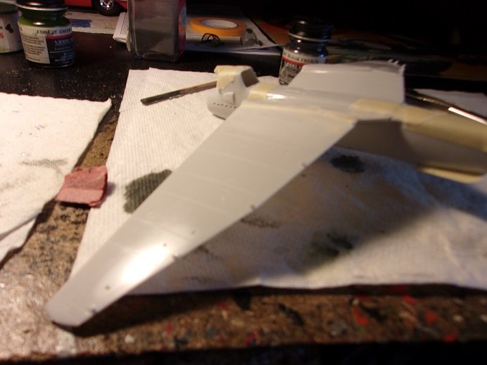
now I will be able to gauge the wing root end better. starting with the center section, it was cemented into place.
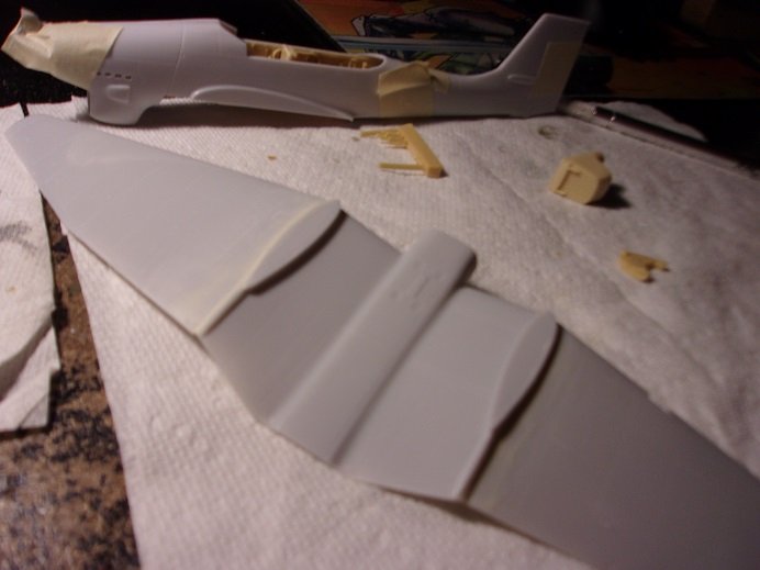
there are some resin parts to add after they are complete. this is actually really neat..........I have said in the past, that these kits..........this aspect of the subject, should be done in separate parts. well, now I'm going to see how this goes......I have gotten my wish! speaking with you further, the outer section was added, beveling where it will join the center section as it relates to the wing shape.
................

 ....schnitzel! I was so busy chatting with you folks, that I forgot to take a picture!!!!
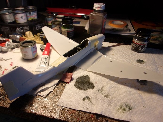
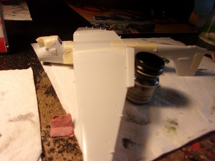
....so, I guess we'll just have to wait till I get the last section on. it too was beveled to fit the shape of the wing edge. the moment of truth!
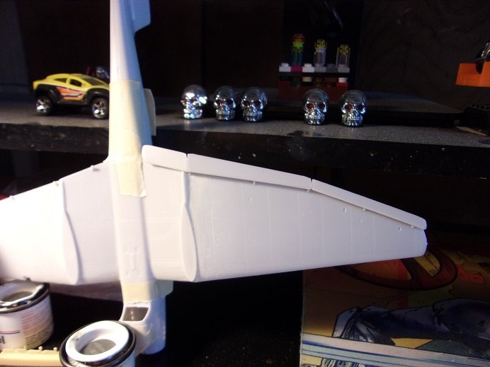
this brings us to where I am at the moment. I will have the other side done by the next update.........and hopefully much more.
-
the M&M ship........the admiral won't part with it! I told her that when she goes to the happy hunting ground, I'm gonna put her ashes in it! I saw your log.......good to see more of your fine work!
both of the wheels are now fitted Ken..........the pants have been painted. I have an idea for the radiator {front and back}.......but I'm concerned for the dive brakes. one of them broke removing it from the mold bar, so I'm in the process of figuring out how to repair it. I should have an update soon!
- Egilman, lmagna, Old Collingwood and 2 others
-
5
-
hello Sam! so good to see you! you caught me in the middle of one of my tangents.......... the instrument panel is a decal.......I sanded the molded detail off the part to get it to lay better on it.
...as for the procedure..... bit of a circulation issue......the valves that line the veins that run up my legs are not as good as they used to be. these valves hold back the blood as the heart pumps fresh blood to the legs and feet, and keeps the blood from running back down between beats. the result is pooling in the feet {mainly, my left leg} and causes the feet to swell....it also developed what could be described as a lesion on the side of my heel. in the legs, there are three major veins.....the procedure shuts off one of the veins to lessen the amount of blood. the way the doc explained it is weird........I think that if one vein is shut off, that would increase the workload on the remaining veins. the obvious thing here is that the veins return the blood......arteries are the ones that supply the blood. I would think it more logical to shut one of those off. but hey.......that's why my insurance pays them the big bucks
- Edwardkenway, Egilman, BLACK VIKING and 6 others
-
8
-
 1
1
-
I rest the sprue protrusion on my thumb nail and whittle with a sharp razor blade....little bits at a time. works fairly well.
- Old Collingwood, Edwardkenway, mtaylor and 2 others
-
4
-
 1
1
-
that's one of the bi products from adding color to the plastic. ...try to break the part away and it comes off like string cheese
-
looking great! really nice progress
- thibaultron, Canute, Edwardkenway and 6 others
-
9
-
-
yea.......gotta love how intrusive the sprue joints can be
really nice job on it so far! been seeing a lot of these military vehicles lately by companies I've never heard of. tempted.....but hesitant about adding another rabbit hole to my collection a super sharp blade against a flat surface might give you a better outcome, and just whittle away the rest.
- CDW, Old Collingwood, mtaylor and 3 others
-
6
-
normally, I get mine from Walgreens as a six pack.......small tubes. larger bottles I find, the nozzles get clogged before I can use it up.
-
hey there EG..........catching up with your project
a few good repairs, a couple of adjustments....and there ya go! we revel in your joy she's look'in good..........a nice start on the paint job your about to do. I also saw your bad news........know that my fingers are crossed for you and am routing for a good outcome. beat it!~
-
something I've not seen.........I've seen either - or........and not a combination like that. some wrote their love's name in some place.....preferably close to the canopy for a sense of closeness........but most names were a poke at their oppressors
- Canute, Edwardkenway, mtaylor and 2 others
-
5
-
sorry to hear of your decal woes......although you still can touch them up. I have to ask........why two names on the nose? American Beauty on one side and Lovely Lila on the other..........are you suggesting the duality of man, sir?
super good job on the paint........an old acquaintance of mine used Alclad extensively
-
-
-
thank you all for joining in. it seems that just playing with the landing gear boots wasn't enough. once I started to play with it, I got carried away
so this is a short run kit Ken there are no date stamps anywhere on the model....nor the instructions or box. the only date I found was the print date on the decal sheet......2000. don't think I've ever done a short run model. I'll try not to let you down
absolutely Egilman.........the resin parts are very detailed.......hard to tell in these pictures I've posted of late. the lamp on my desk died, so the admiral went out and bought me this LED lamp. it's pretty bright and so far the pictures have been decent. I'll try and get better ones so you can see how nice these parts are.
welcome to you Alan and Jack........good to have you folks look'in in
the kit also features an expansive paint by number.........just about everything has a color number associated with it. as with any kit, there is the usual flash clean up.......especially where the sprue connects to the part. it seems to carry onto the mating surfaces. one thing I forgot to mention was that I had done some clean up to the cockpit floor prior to mess'in with it. the floor was a bit thick......the underside was very shiny and slightly sunken...likely the 'sunny side up' from being produced. noting the thickness of the floor in the Revell kit, I brought the thickness down by rubbing it on a large sheet of sandpaper. sanding all around the outer edge, I concentrated on the starboard side aft, to even the taper to mimic the port side. the fuselage was taped back together.......it was a tight fit, but I managed to slide the floor in place. to make it a better fit a small amount of plastic was removed from the opening below the gunner's compartment, in contour with the wing root........the underside of the floor {aft}....both edges were rounded to fit in the space better. the floor comes out now, like a cartridge.
still a bit blurry {I'll get a good one yet
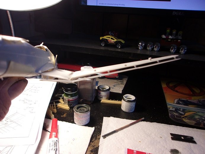
I have two options here.......I can keep doing it like this and risk breaking something in the future, but I think I'm going to cement one side of the floor to the inner wall {preferably the starboard side} and save myself some grief. I may have to shave a bit more here and there. the pieces of the wings were cemented together, only using the upper surfaces as a template for the dihedral. only the three bottom parts were glued together.
any gaps seen on the outer surface were filler with putty and left over night to dry. I sanded them today.
the chunk off to the right has the front and read radiator detail on it.......it is to be added as a plug. problem is.....it is too small causing it to be indented to much. I'm going to cut it and fit the radiator faces in their proper places.
in tinkering with the landing gear boots a bit more........this would be acceptable to me. I may remove a tiny bit of the axle bumps.......perhaps it will go in a tad deeper. now to get the other 'shoe on the right foot
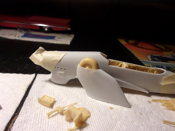
the machine gun is there.........very nice detail. .....something else I see..............a better shot of the cockpit!
very detailed! when I have the fuselage split, perhaps I can show more
-
hi there Egilman....welcome to ze flying zircus! I will say this.........the ending will be textbook, but the beginnings will definitely be out of the norm
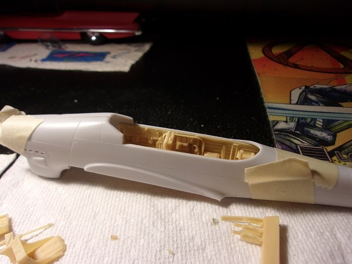
I tried to get a decent picture of the cockpit floor and walls, but for some reason, they came out blurry.
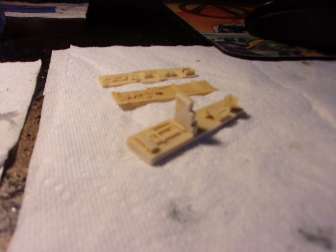
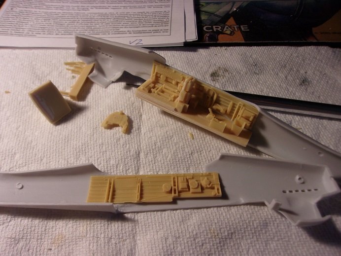
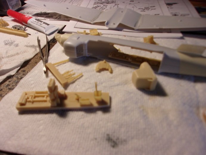
the walls needed to be cut off their blocks.......areas of the walls are very thin. there was a slight issue. the partition was cleaned up and is the first part glued into place. I sanded the thickness down to make it even {in thickness} and flat. there is flash.........hard to discern what is part or flash. I was going to wait for the picture to tell you, but the taper to the cockpit floor is off too, which is enough to make one doubt putting it together.
the pilot seat and gunner seat had to be cut from their blocks. in between the pilot seat legs had to be removed as well. both of them cracked, but not severe enough to lose them....a little CA fixed them up.
after dry fitting the walls on the floor...........I just didn't feel confident enough to put glue to them. the interior of the dry fitted fuselage was examined........the injection pin marks were removed..........taped back up and examined again. don't know whether to bite the bullet or chew on the shell
 they show the model being assembled with the cockpit as a whole.........but considering the shape of the floor, I chose the later
the walls were glued in place using the marks provided.........you can see the off-ness of the floor. the machine gun post was also glued to the floor.........it broke off the block and I almost lost it. the walls were clamped and set aside for the Ca to set. gotta head out for a bit............still got more to add here. go get a beer......ya look parched
- Canute, king derelict, mtaylor and 4 others
-
7
-
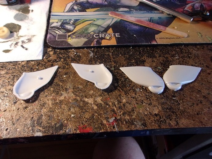
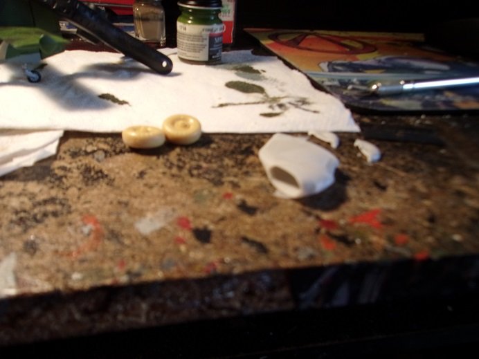
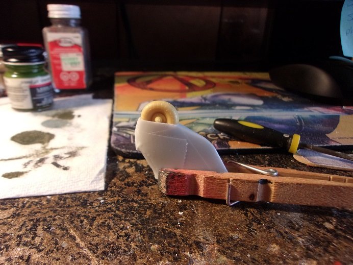
the landing gear boot halves were cut from the sprue. the protruding tire detail will be cut off. the resin tires look a bit fatter though.......but once I do this, there is no turning back.
the resin tires were separated from their block and cleaned up. one thing noticed here is the thickness of the plastic.......this might be something in my favor. here goes nothing........
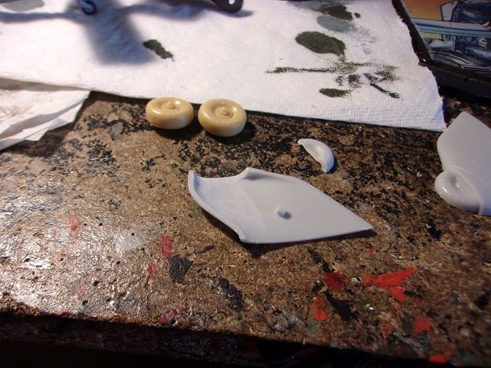
the excess was trimmed out of the well.......keeping a thin wall around the opening. the mating side was cut and trimmed out to match.
I made up a sandpaper dowel to assist me with the shaping. I had taped the two halves together.......held together, but still prone to shifting. I continued until both boots were hollowed out.
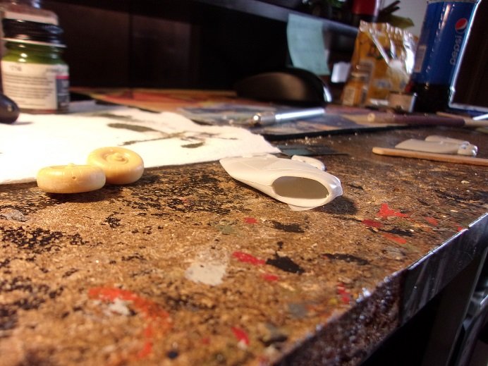
I kept them taped for the time being....the idea of having them moveable was beginning to become very doubtful {the reason why I tape them in the first place}. especially when I saw how much more I had to go.
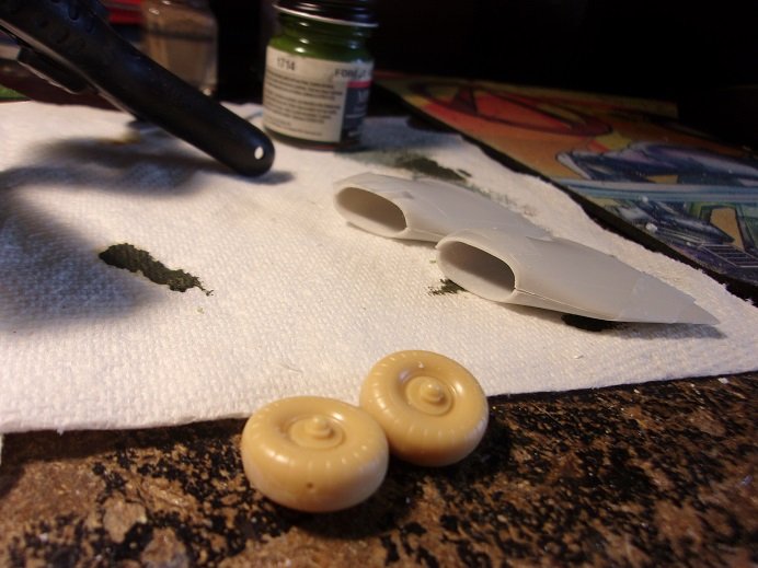
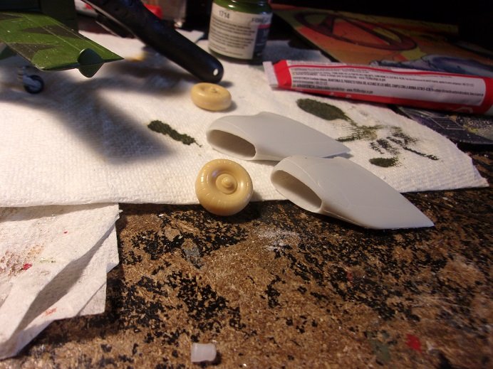
more enlargement.........then flat across the opening to keep it even. I'm losing more towards the rear, the only way to go in order to enlarge the opening. I even looked through my spare parts to see if I had another pair of tires.....yea, but wrong scale. press on Mc Duff..........I finally arrived with them looking like this.....
the fact that they have their axles prevents them from going inside, but they look like they could drop in. I was going to drill holes for the axles, but miscalculating seemed kinda scary. I figurred of getting the axles just past the opening lip and being happy with it. I decided to glue the halves together at this point......
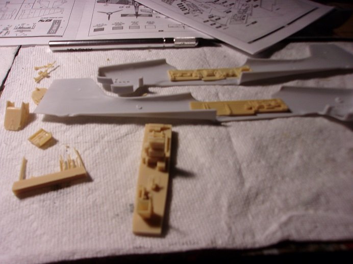
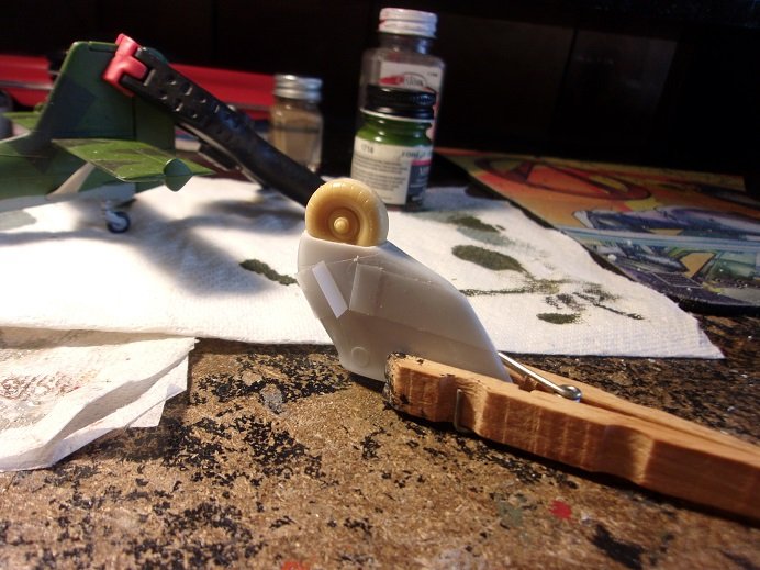
the openings need to be more tire shaped, and less oval.........which led to the half hearted squaring out of the openings. for a break away from all the sanding, I put the fuselage halves together in a dry fit to see what I was up against with that..........
the no locator pin thing is very telling with the fuselage..........the cockpit section give it sort of a flimsy feeling. it's gonna slide around a lot as I clamp it. it's got some roughness around the edges too. I did notice that there are marks to show where the cockpit walls should be, but I will need to remove the injection pin marks that will be in the way. the cockpit was on my mind at this point.........whether or not to assemble the cockpit with or without the inner side walls. but if I did that, would they mate up with the outer walls of the sides without gaps? there are a few tooling errors here and there that will need to be cleaned up........I fear that the resin is going to be just as bad. the thoughts were over whelming........I just had to see.
-
As mentioned, I will separate this one from the original Stuka log, due to the fact that it's an earlier variant. I've heard about this company, but I've never built one of their models. the box art is what caught my eye.
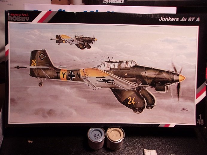
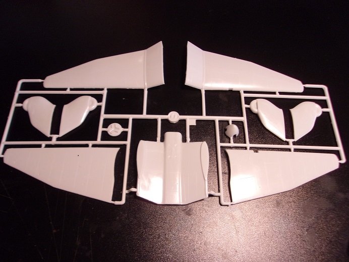
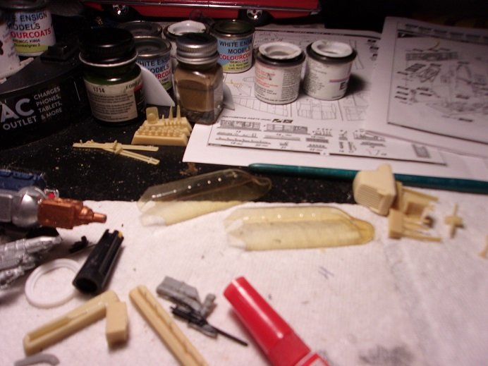
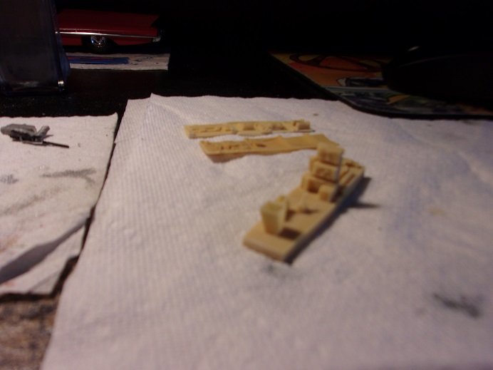
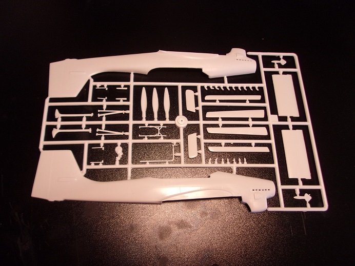
the wings is made up of five sections.......the other thing is the lack of locator pins or tabs. it becomes critical to line things up properly. the kit comes with resin parts....one being a set of tires. the landing gear boots, as can be seen, has tire detail molded in place. to fit the resin tires in the boots will be the first feat of modification madness
the instructions is fairly detailed in regards to the resin parts, but not for the tires and exact locations.
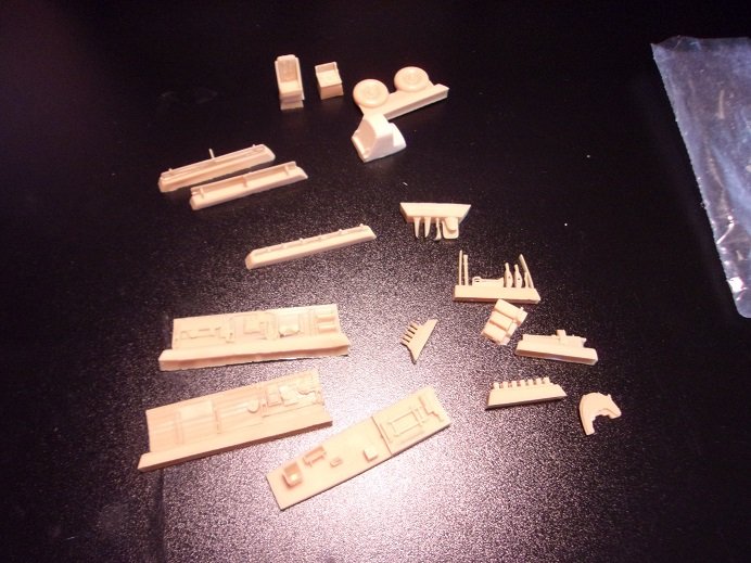
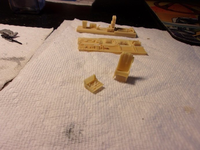
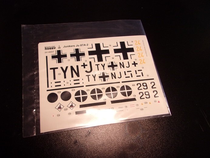
these are the resin parts.......confusing at first, but once I caught on with how they did the count on everything, I saw that all the parts are here. the canopy seems to be the exception.......I got two of them.
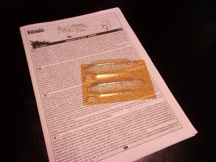
not sure if the yellowing is OK or not.......I'll see when I get into it. the decals are a bit bland, but I'll try and make up for it with the overall paint {I hope}.
I figured I'd start this one after the G1 was finished, but watching paint dry is boring. so I gathered the parts for the landing gear boots and get the party started
- mtaylor, Canute, GrandpaPhil and 4 others
-
7
F-86F-30 Sabre by Egilman - Kinetic - 1/32nd scale
in Non-ship/categorised builds
Posted
yep......decals can be a problem. either they are too glossy or flat, or they are thick or thin........thin making them more prone to cracking. you could paint the yellow and then source out black pinstripe decaling to finish it off. you can also print black stripe decal on your computer. I have a decal program as well. there are thing at your disposal that you can do. super silver job overall.........I think you succeeded quite well!")