No Idea
-
Posts
1,036 -
Joined
-
Last visited
Content Type
Profiles
Forums
Gallery
Events
Everything posted by No Idea
-
 Hi Tony - if you have a look at the scantlings in the monograph you will find the thicknesses of the wood required. As for the amount of each thickness I just guessed. I actually thought that I over ordered but I’ve made so many pieces several times that I will have to buy some more before the end of the build.
 -
It really is isn't it - the prep work for raising the frames is inspiring!!
-
Cheers druxey and aren't they just...... It's funny as some of the parts that I thought would be fairly ok to make have caused me the most effort. I'm glad these are done as at one point I thought that they were beyond me. I like this scale but at 1/24th some of the timbers are just so thick. I really makes you wonder of the skill of the original builders.
-
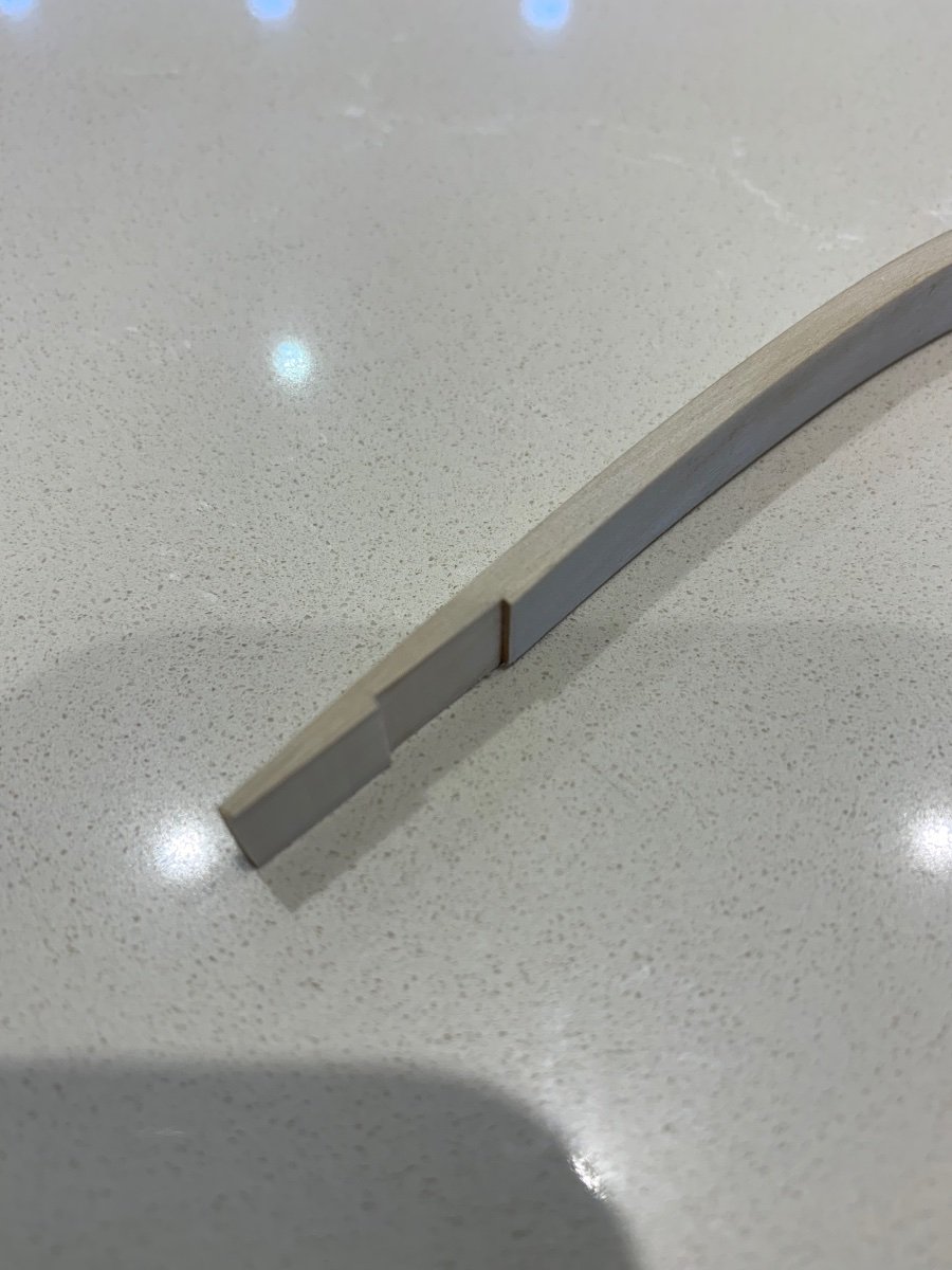
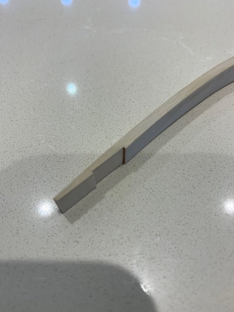
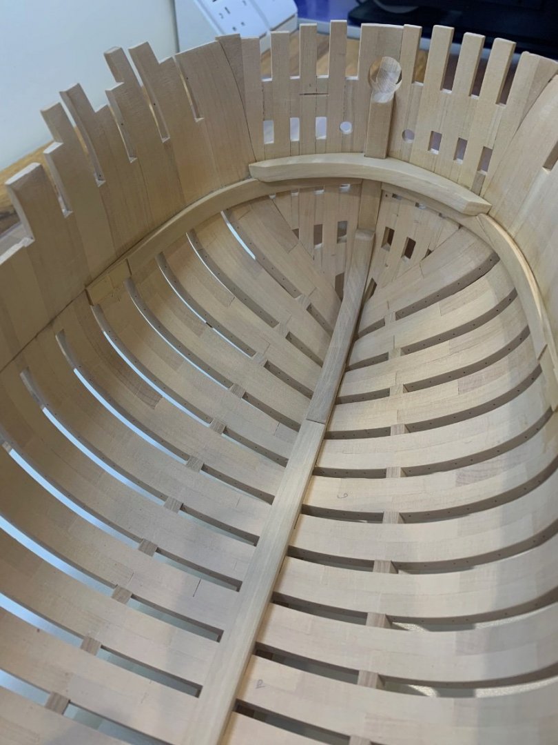
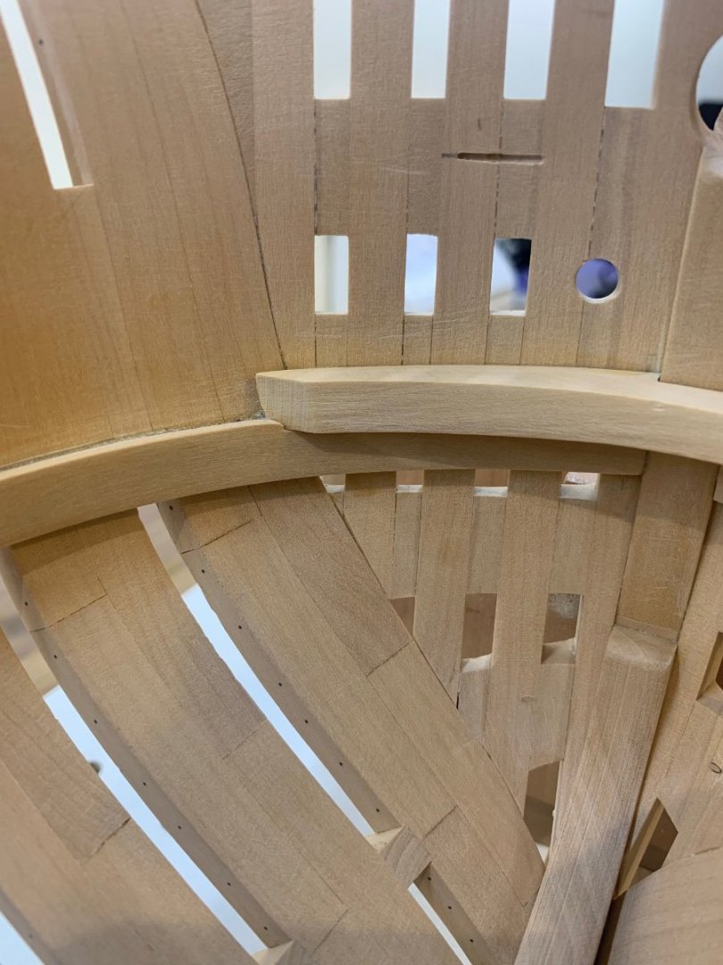
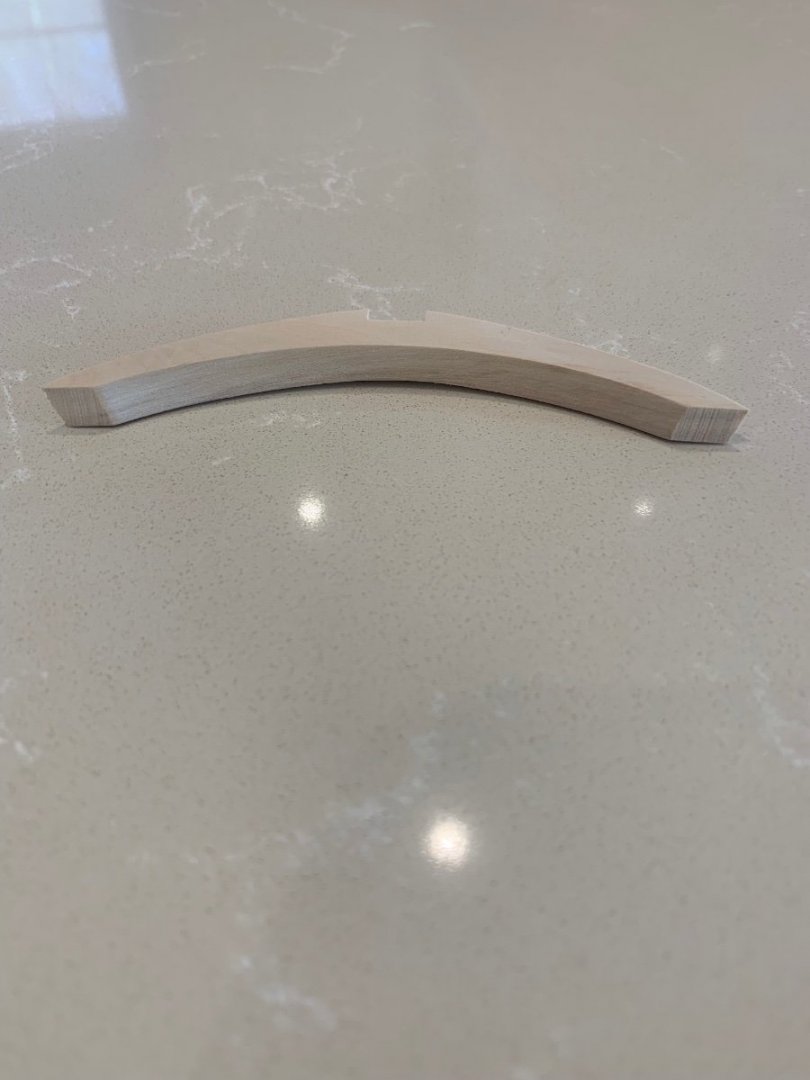
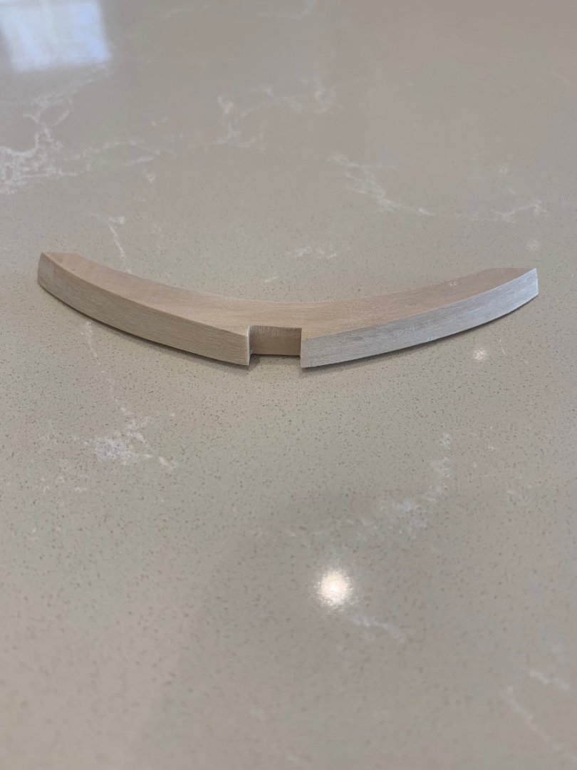
Hi All I think it's safe to say that these three pieces have been very difficult for me to get right. I eventually made 4 deck clamps before being happy enough to fit them to the model. The combination of difficult bends that have to be recessed for the breast hook which all have to be sat on the correct line inside the hull.............wow! Anyway I've now got it done but not without a little damage. The port side deck clamp glued in fine but the starboard side cracked; I didn't even notice it until the next morning when I removed all of the clamps. It was one of those times when I just though - well its not very pretty but I do know that its in exactly the correct position. So I opened the crack up a bit and fitted a sliver of wood in just so that it looked a bit better. I'll put this one down as a ships repair 🤣 I've also had a go at making my first every hooked scarf joint and I think its going to be fine with a little adjustment. So the next steps are to make the 6 remaining pieces of the deck clamp which are all joined with hooked scarf joints. I must be honest I'm really pleased with the result mainly because structurally I know that its correct. Mark
-
I can't even imagine how hard that was to cut those angles so accurately - that lantern is simply outstanding 👍 Can you make me one 🤣
- 589 replies
-
- 3
-

-
- le gros ventre
- cargo
- (and 1 more)
-
Hello and welcome to the forum. When I joined I also thought exactly the same as you are now and I discovered the most helpful and friendly place. Good luck with your builds!
-
Personally I think that looks amazing - Even better its your own work
-
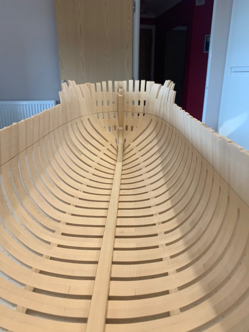
Thanks druxey and funnily enough I wanted to poke the height gauge through the frames as that would have been so much easier! Unfortunately where this line is on the hull its on all of the spacers on the frames so I had to go over the top I just need to check my alignment at the stern to make sure the beams will be high enough. It's no big deal I just need to be sure before I fix anything in. Thanks Christian I hoping to get an update on this build up soon but our daughter needs some Dad's DIY doing and its taking up most of my time. Having said that I'm just about to have an hour on Le Rochefort now in-between painting 😄
-
No problem Dave in fact I need to put another order into them soon. I’ve never had a bad piece from them and the service is great.
-
Greg and WalrusGuy - thanks both 👍 It still needs a bit more fitting to get it all a bit tighter but its just about there now. I think the time taken now getting it right will save a lot of adjustments later on. I still need to bend the starboard side deck clamp and then I'll have a go at the hooked scarf joints which should be fun Cheers Mark
-
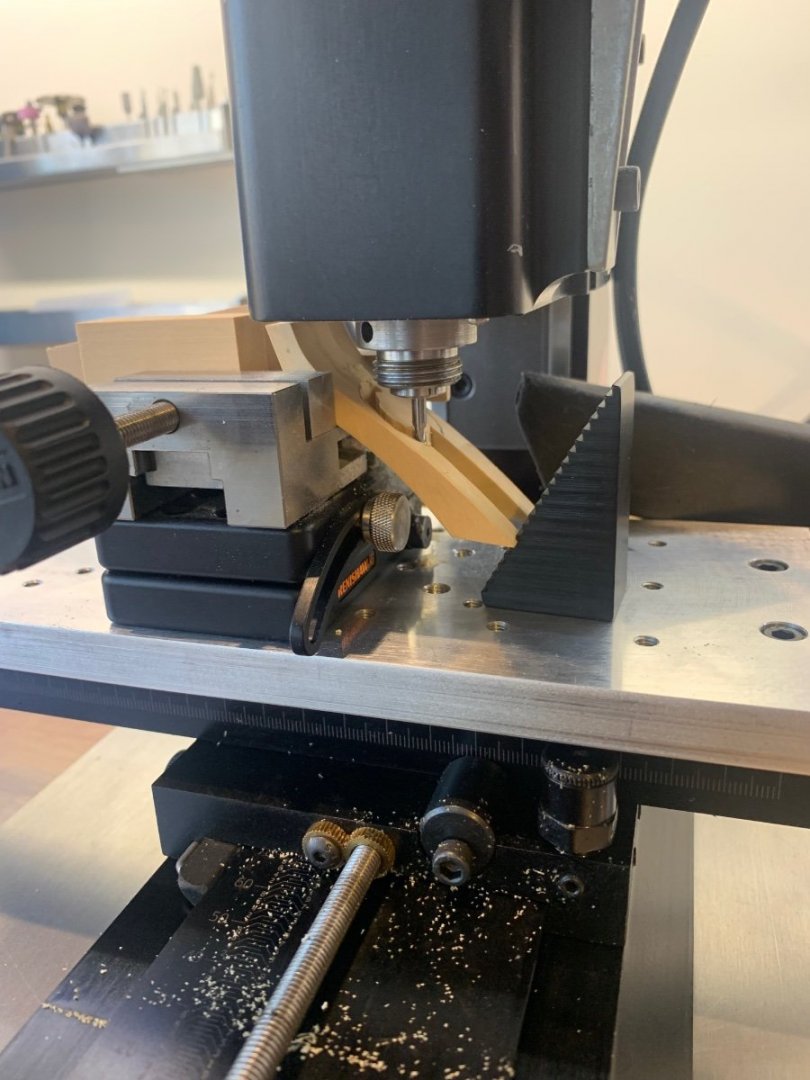
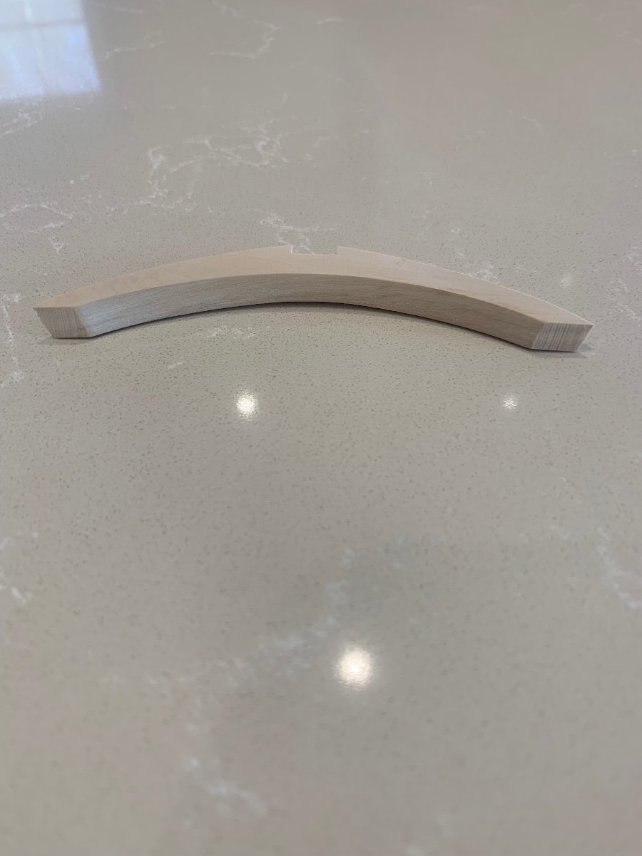
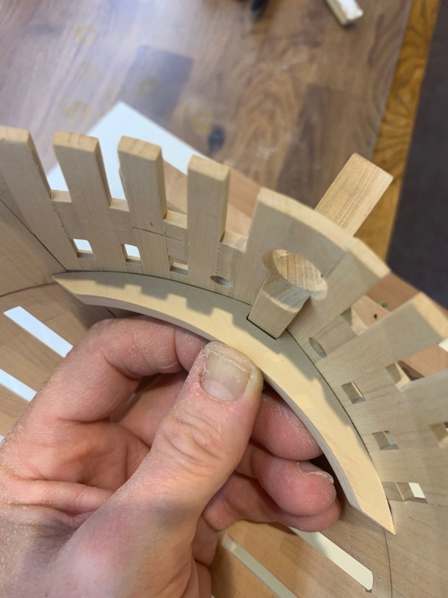
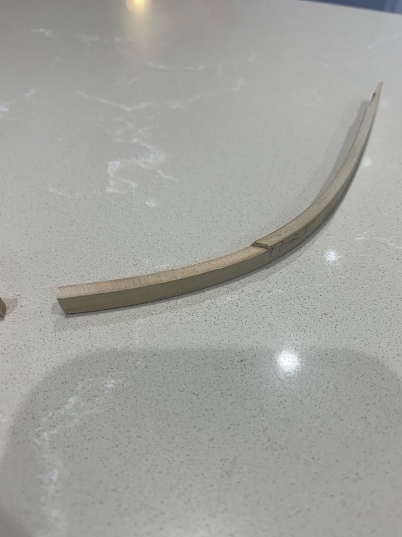
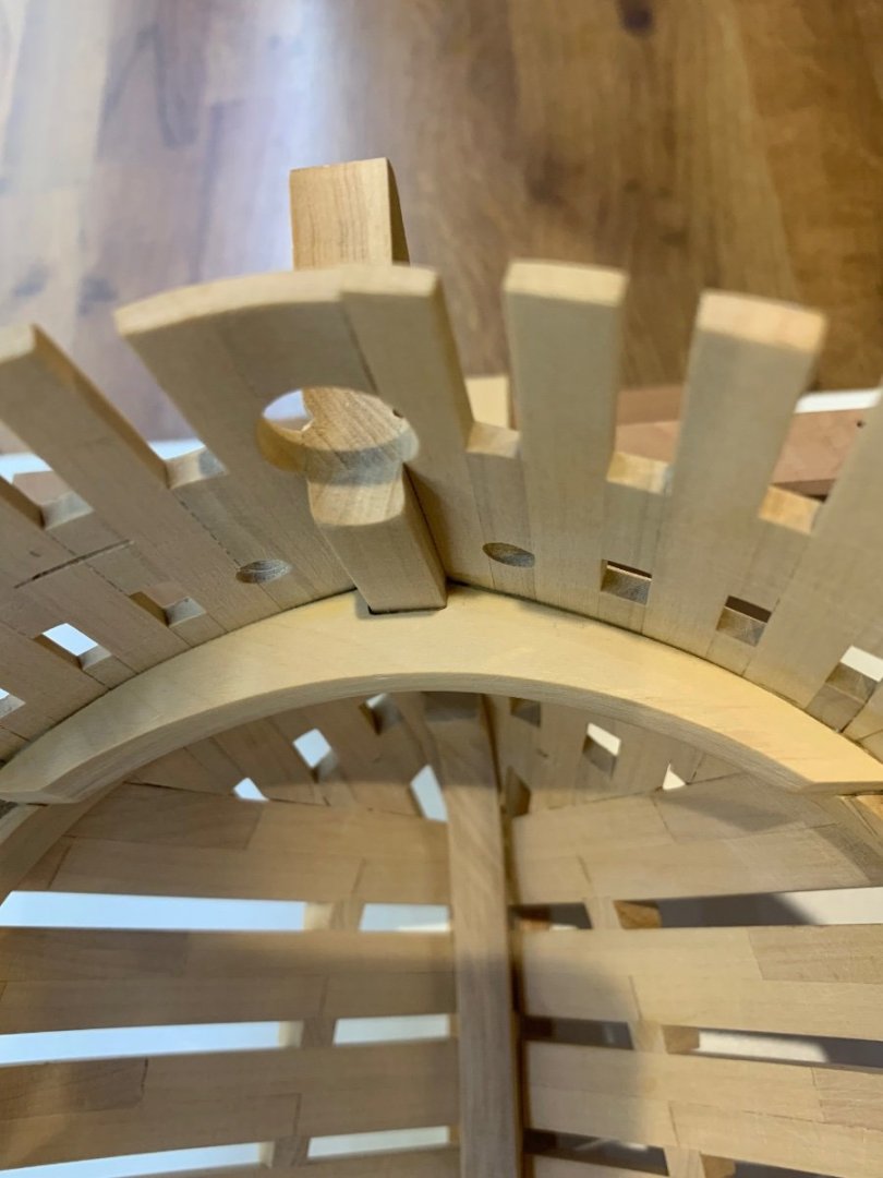
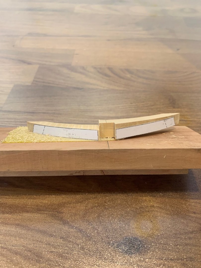
Hi All Firstly thanks for all of the comments and you were all correct! The wood stayed discoloured, it was very very brittle and the bend on the former was insufficient. So having learnt I started again but this time simply using water and heat as I have always done in the past funnily enough. I also made the former more of a curve and I also introduced the frames camber onto it as well. It all went well and there are a couple of pictures below. I have also made the third breast hook which fits into long notches that need to be cut into the deck clamp. This hook is different to all of the other four as its profile is not flat. It has an angle across its width which mirrors the angle of the deck. Once I had worked out the cutting sequence it actually wasn't too hard to make. I just had to replace the templates often as I ended up having to cut them off during the machining. Again there are a few pictures below which I hope explain better what I have done. So a bit more progress and thanks once again to you all Mark


-
NAIAD 1797 by Bitao - 1:60
No Idea replied to Bitao's topic in - Build logs for subjects built 1751 - 1800
Happy new year mate!!! Awesome work on the ship too 😀 -
Vahur - Thanks for the information as I was looking for some black wood too for my build. I'll place an order with you at some point over the next few months. Thank goodness for model suppliers!
-
Wow the accuracy of your work is astounding.
-
Sorry I should have said that this is a 90 degree router bit for your Proxxon. They are not cheap but its what I use https://www.leevalley.com/en-ca/shop/tools/power-tool-accessories/router-bits/111107-1-8-inch-shank-carbide-tipped-v-groove-router-bit?item=86J0423 Mark
-
Hi Dave - I get all of my Castello from Timberline and have found them to be fantastic. If you give them a call and explain that you are making a model ship, I have found that they will send you the best wood that they can. They have also custom cut lengths for me at 8mm which they do charge for and I also had to wait. However it really was worth it. Having said that I haven't used anyone else in the UK.
-
druxey I think that you are probably right but I've never tried it before so I thought - why not give it a go! I have to say that the wood literally bent with light finger pressure. I probably won't use this method again as ammonia is a horrible product that you certainly do not want inside your home. Having said that I'm glad that I've tried it at least once.
-
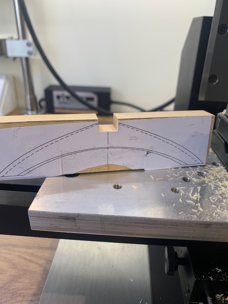
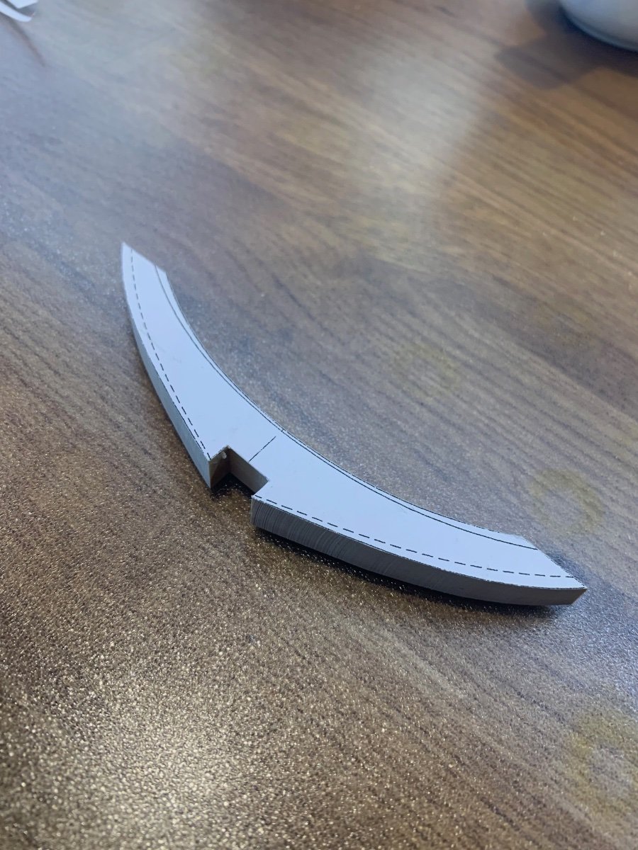
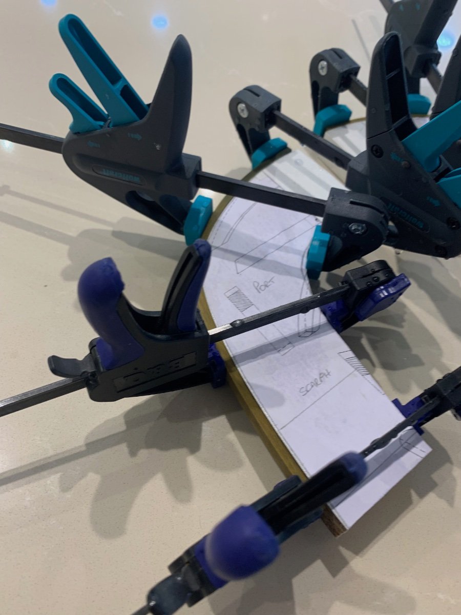
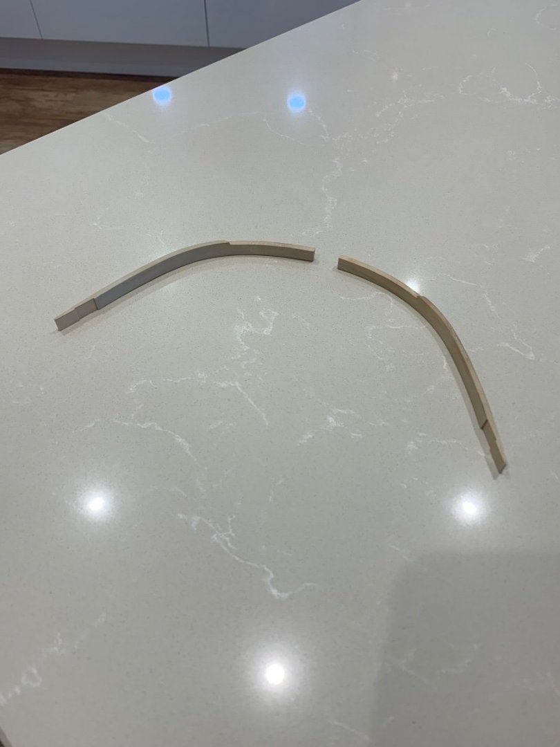
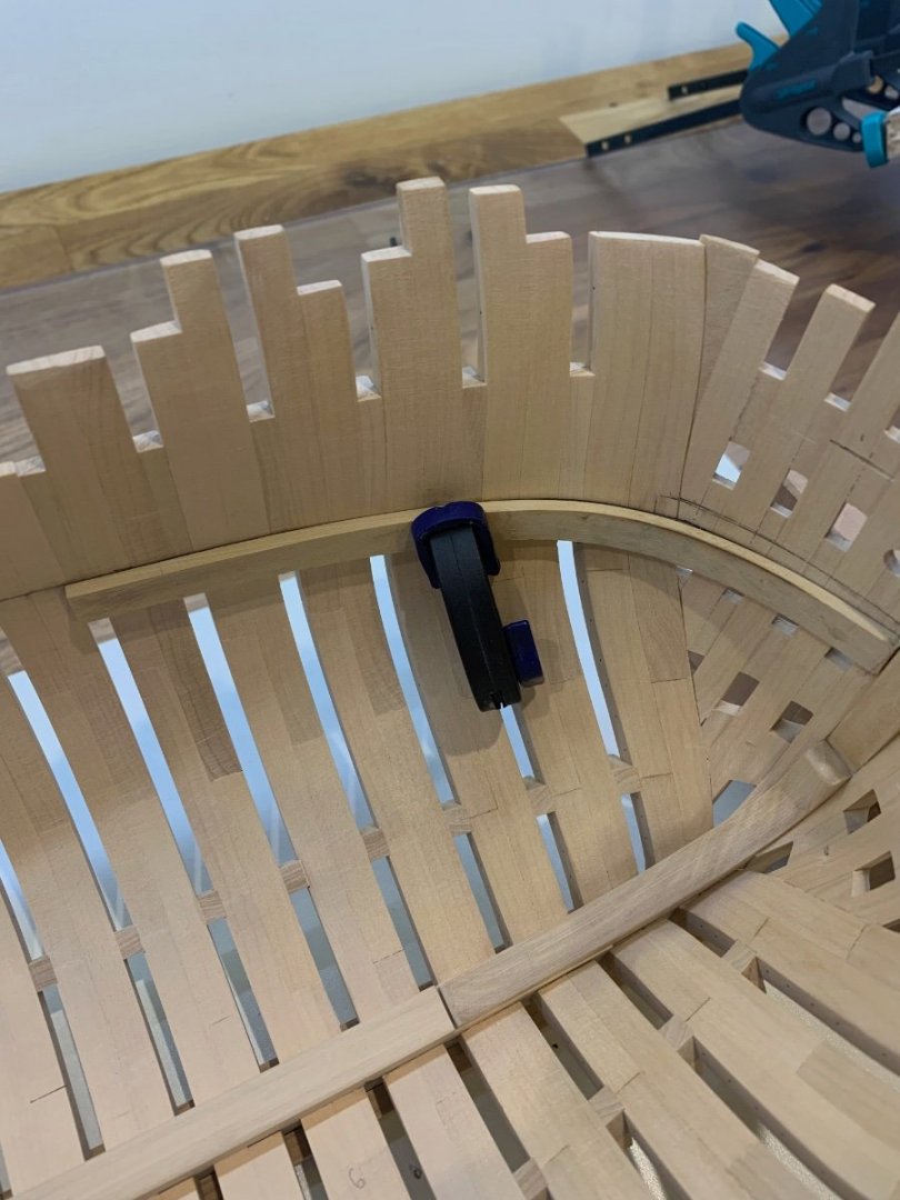
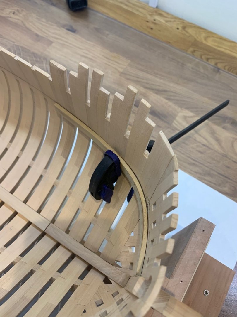
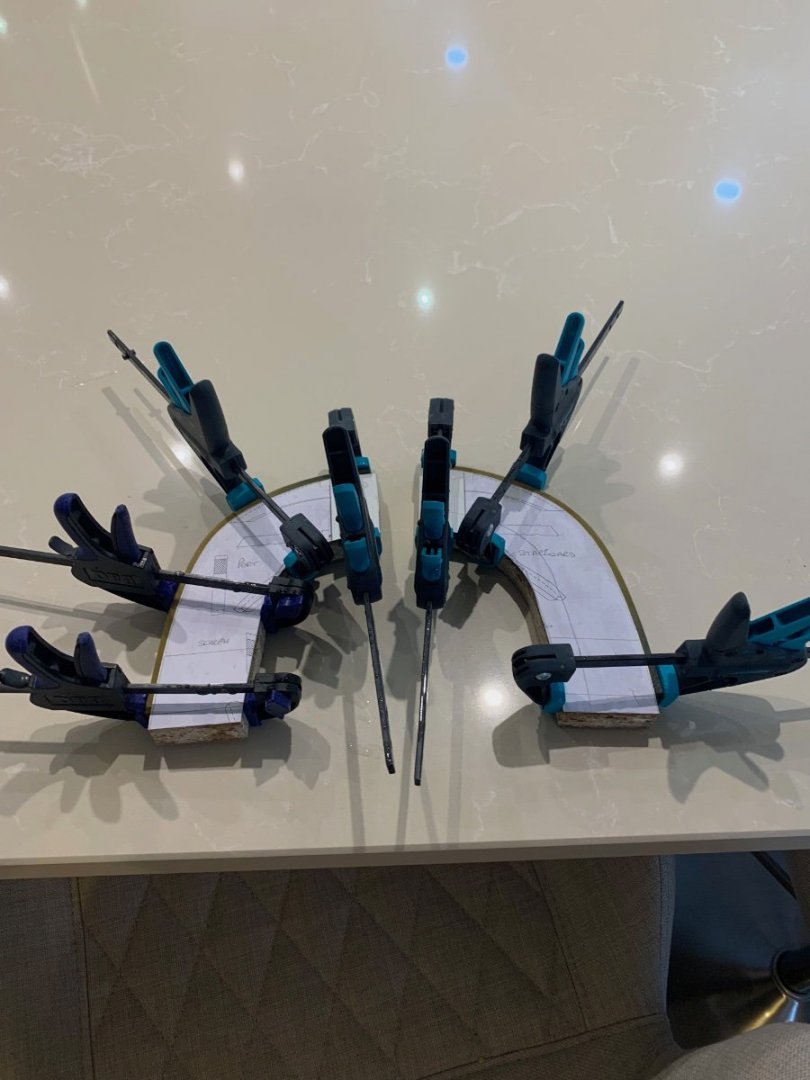
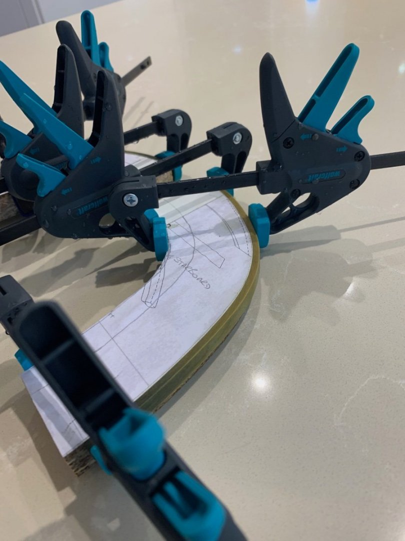
Hi everyone Work on Le Rochforte has slowed to a glacial pace as installing the deck clamp is a bit harder than I thought. After hours of looking at the plans I was certain that the deck clamp at the bow had to run underneath the third breast hook. So to be sure I dropped Gerard Delacroix a message and he confirmed that this was correct. He also pointed out that the decking is nailed directly to the third breast hook so the relationship between all of these parts is critical. So I have spent a lot of time marking the positions of these parts out inside the hull and I'm pretty sure I've got it about right now. I also have a much better understanding of the construction. Anyway back to the pre-bending of the deck clamp at the bow. I made up a pair of formers to the correct bend out of some scrap chip board. As the timber is 9mm x 3.4mm I didn't think that heat would be the way to go. So as a first experiment I soaked the wood for 24 hours in a diluted ammonia solution. The pieces bent around the former very easily and so far have not cracked in any way. The only issue is that the wood has changed colour, but this may be ok once the wood has dried. If not I'll try another method nest weekend; I'll let you know Mark


-
Byrnes table saw blade for cutting planks
No Idea replied to genericDave's topic in Modeling tools and Workshop Equipment
Hi Bill - If I were cutting the 1/8 thick board I would be using a .30" or .40" slitting blade as both of these would be ok. It all depends on how much kerf you are prepared to loose. The .40" will generally in my experience hold a straighter line over many cuts than the .30" blade. This is simply down to the users experience and knowledge of their tool. For the 3/4' cut I would use a carbide tipped blade. You will loose far more through the kerf of the blade but the cut will be very easy to do with this blade. Many others will have different opinions but thats the beauty of what we do. We do what works for us. -
I'm a few (many) years late to your build - but wow what dedication and determination. This is simply amazing and I'll be following your work from now on!!!
- 2,623 replies
-
- 5
-
-
- heller
- soleil royal
- (and 9 more)
-
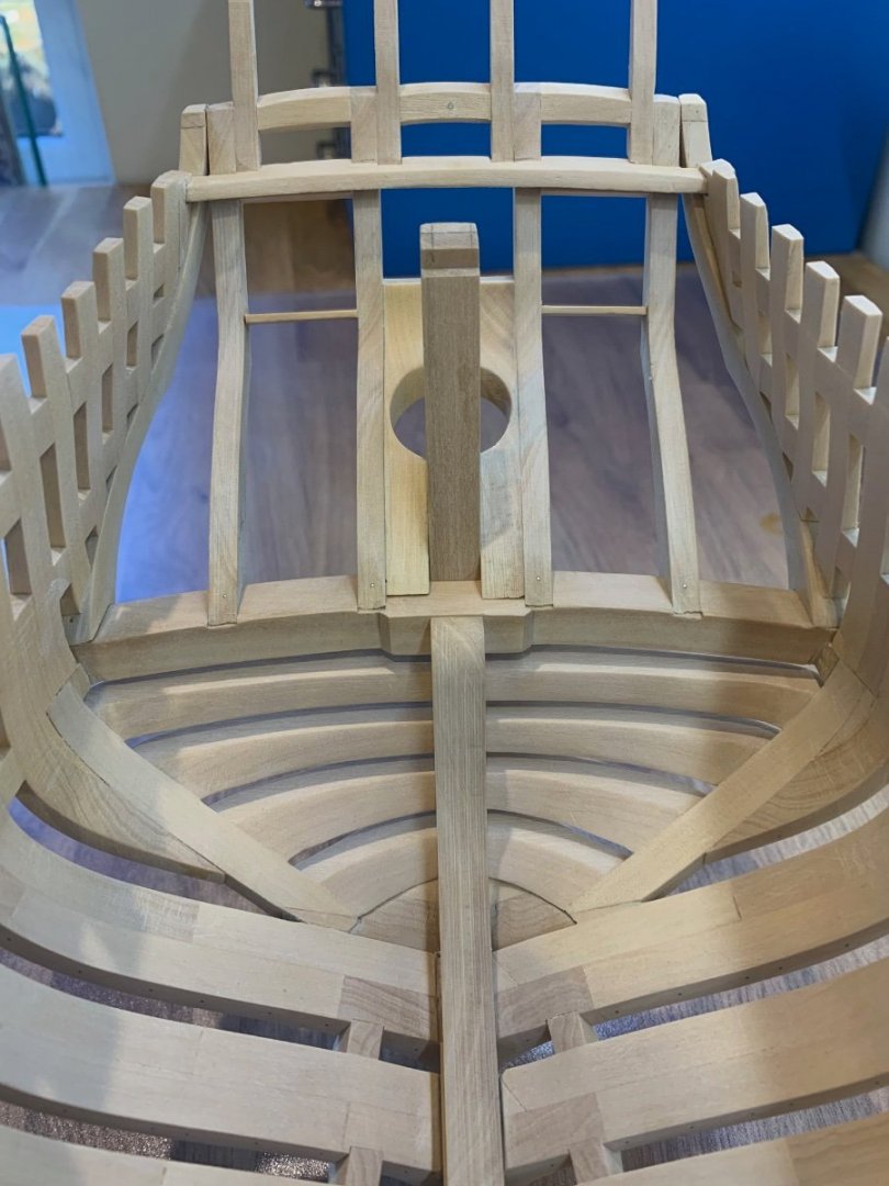
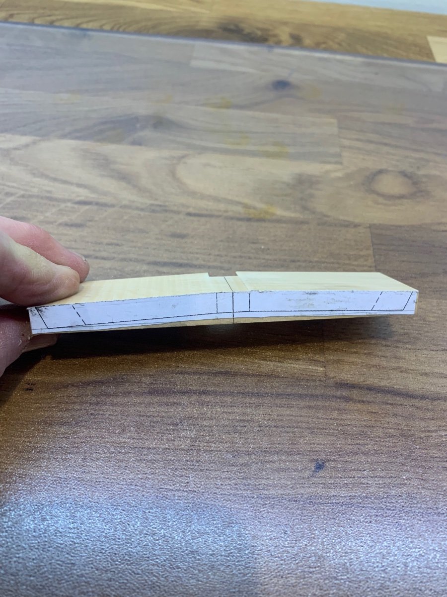
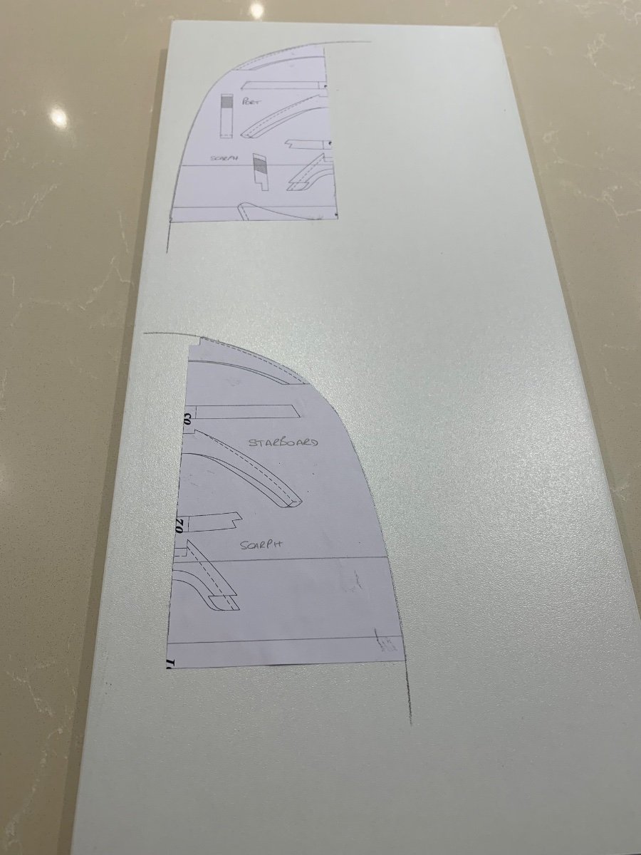
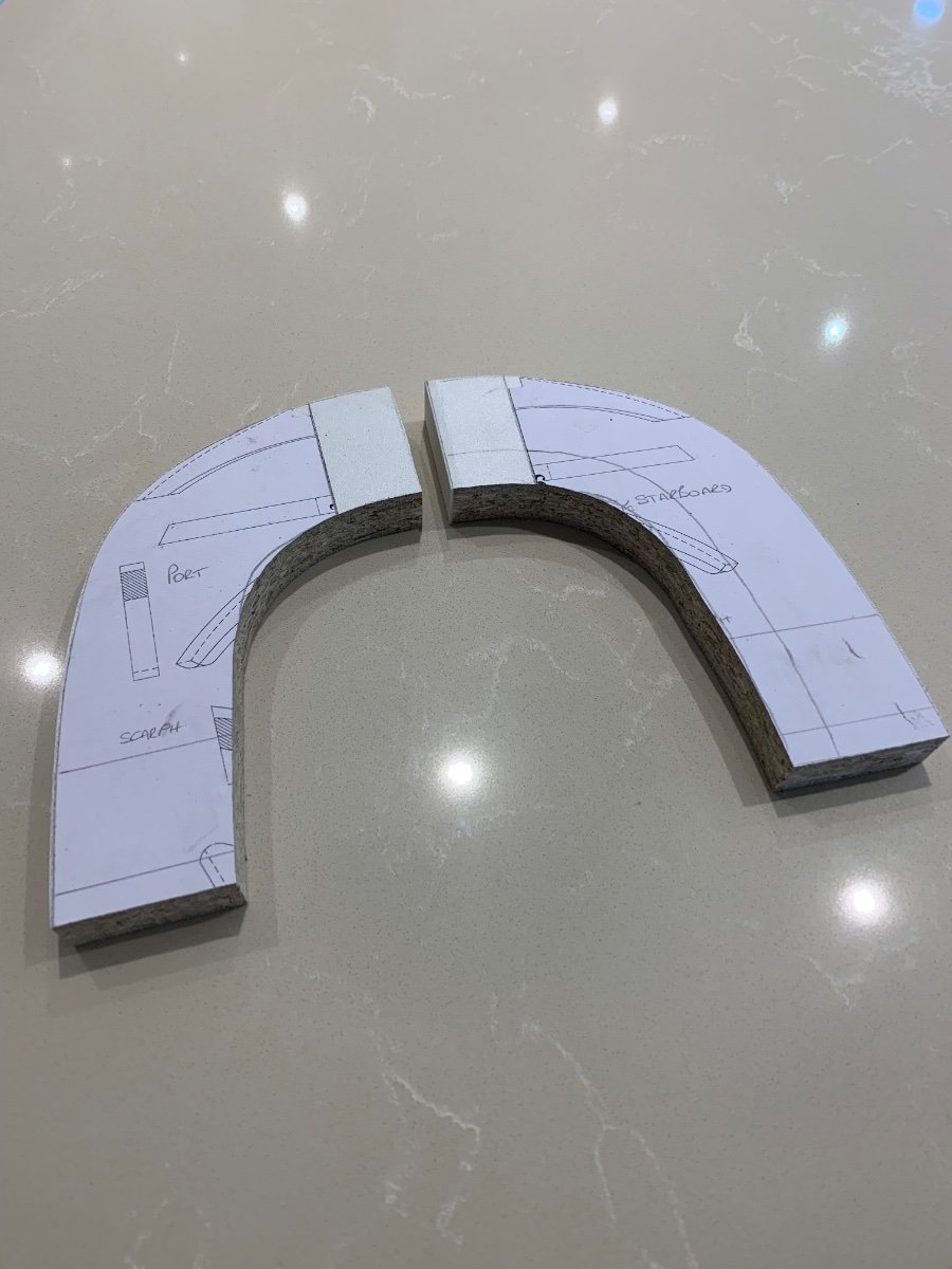
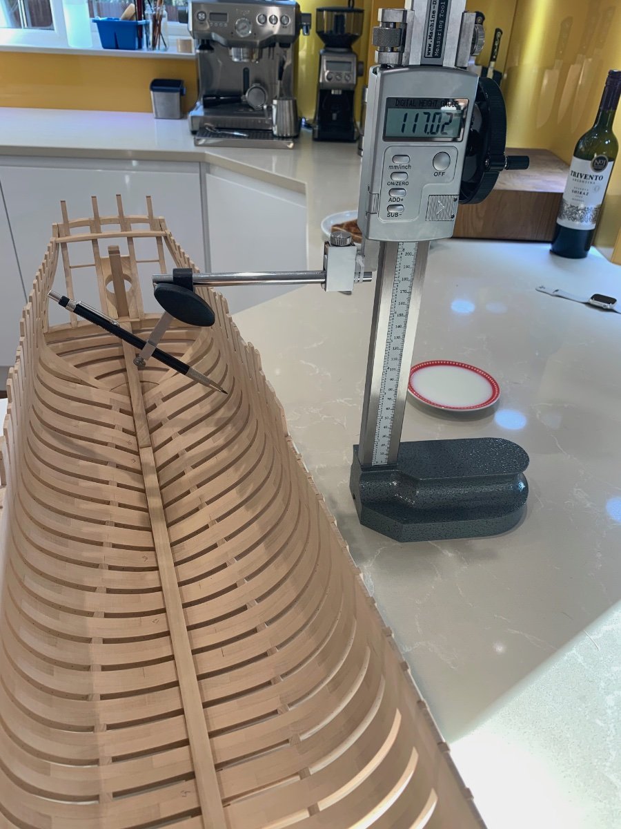
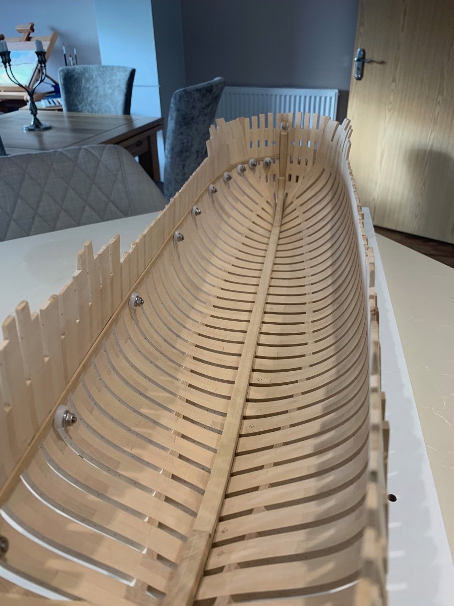
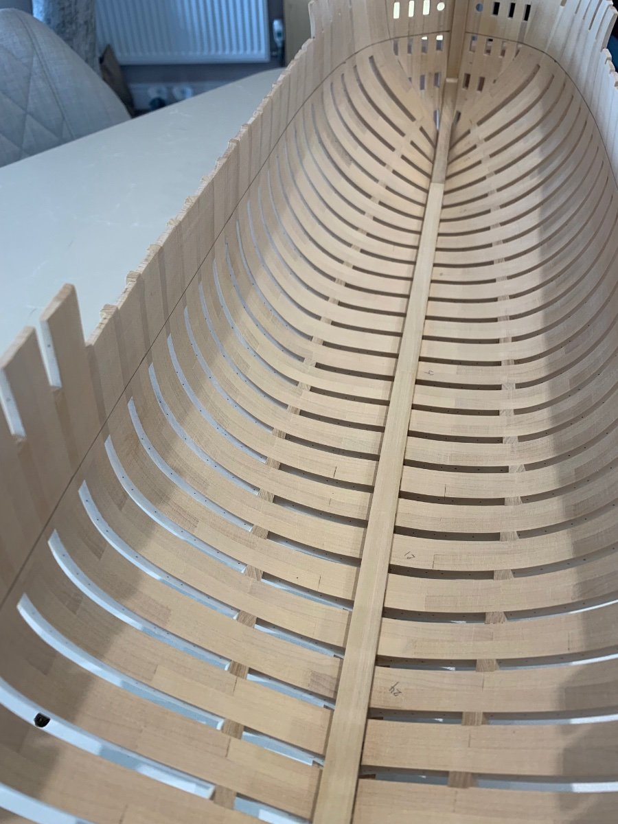
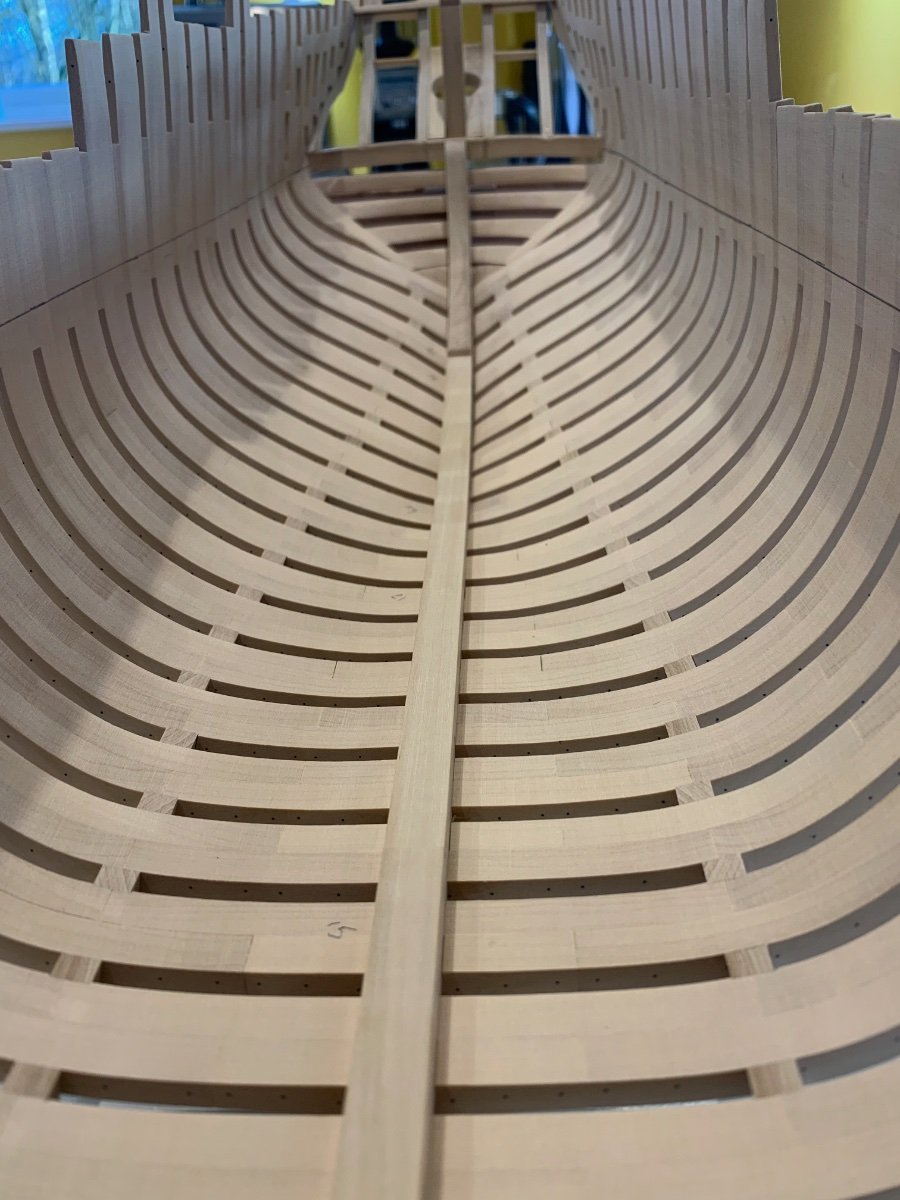
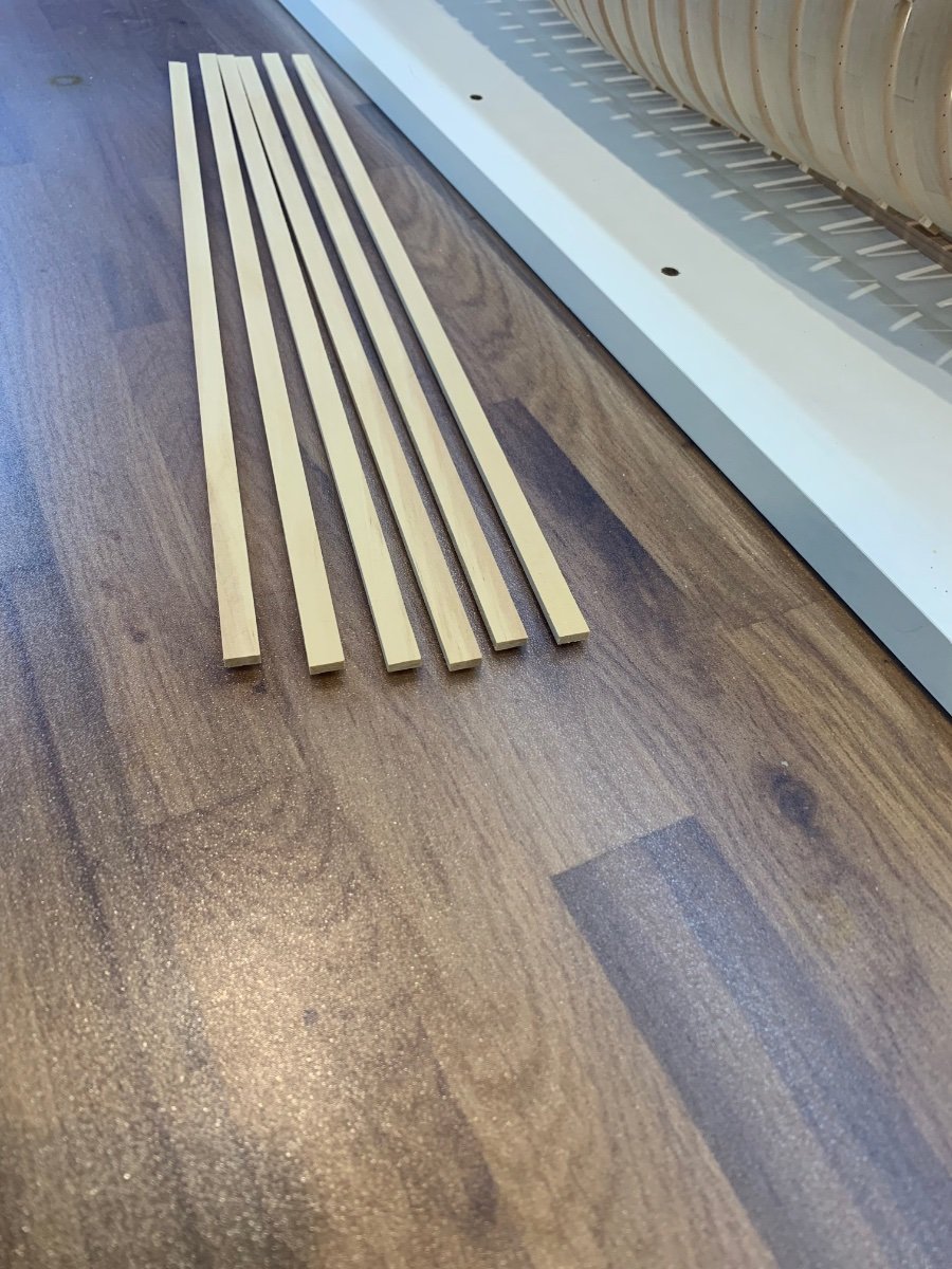
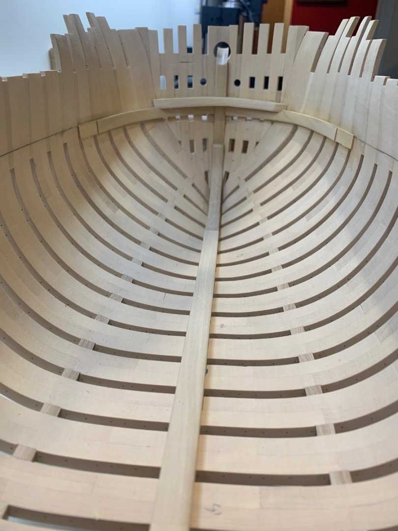
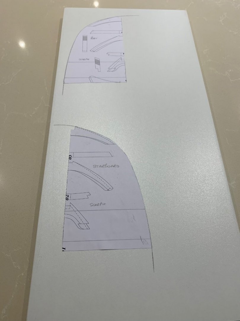
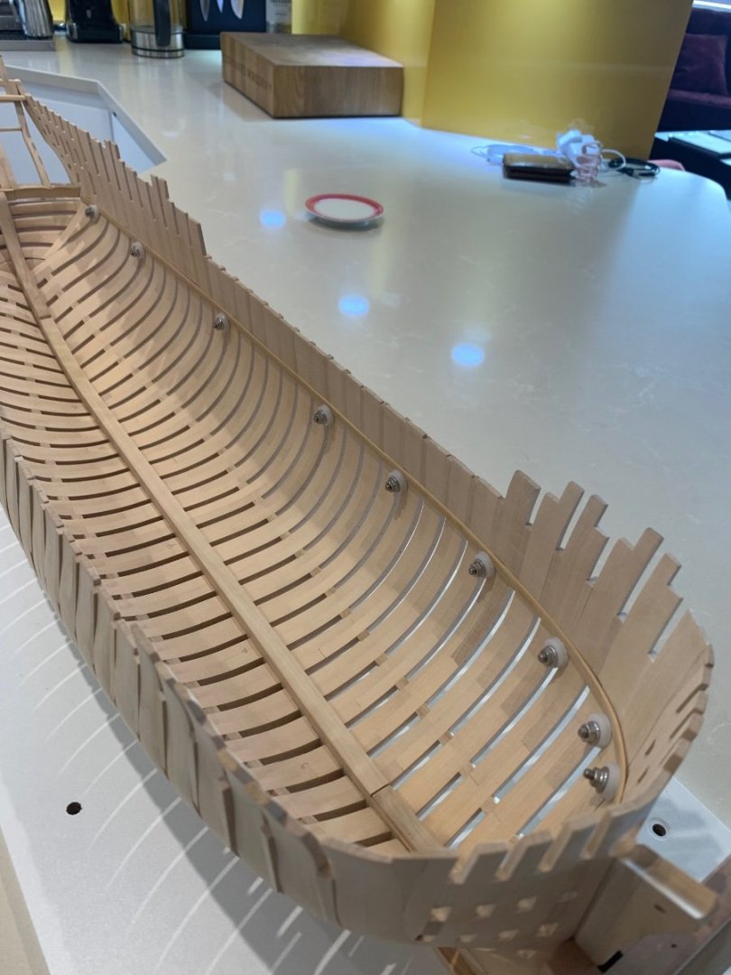
Marking out the deck clamp - I took the measurements for both the height of the clamp and the clamp dimensions from the cross sectional drawings. I then had to think of a way of marking it accurately inside the hull. I did think about drilling small 0.5mm holes from the outside to get my marks but decided against this. In the end I modified my height gauge which worked really nicely and was actually very simple to do. Next I joined up my marks by using a strip of wood which I temporally clamped in place. I now have a nice solid line to put the actual clamp up too, and its nice and even all of the way around the inside which must be a good sign. Now is going to be the hard part - The clamp at this scale of 1/24 is a piece of timber 3.4mm thick by 9mm wide and I have cut these in readiness. The problem is definitely going to be the bow as the curve due to the dutch style construction of the hawse timbers is quite severe. The timbers themselves are far too fragile to get any sort of heavy clamping going on so I need to preform the clamp curve at this point. I'm going to make a jig to try and bend the clamp into shape - It may work; it may not due to the thickness of the timber and the harsh curve but I'm going to give it a try. My other option is to spile this piece but I don't think that this will be any easier. There is no way I can spile it spot on to the curve and camber so to would probably need a bit of clamping to pull it tight. The problem for me then would be that the grain would be all wrong and I think that it would snap. The other issue for me is that the clamp is made up of 4 individual pieces which are joined with a hooked scarph joint. This will be another first for me but I do like a challenge. I may not get any posts up next week as I have a lot to solve but that surely is the fun in what we do! Mark (Sorry for some reason my photo's have all appeared back to front )


-
Thanks Greg and that was great advice too. I made a piece of rudder as you suggested and found that I needed to remove more material right at the stern post to get clearance.

-
Who dares wins 🤣 I just couldn't see a way of removing so much material with it on the ship without loads of damage. I could have done with a longer end mill though as I was using its entire cutting surface which is never a good thing.
-
Hi WalrusGuy - I think that you are spot on about the finished shape 👍 I've left it slightly small as I can't really see the final shape on the plans. It's nothing to do with the plans as all of the information is there I just can't see it for some reason. So I thought that I would wait until I've made the rudder and then hopefully all will become clearer to me.
-
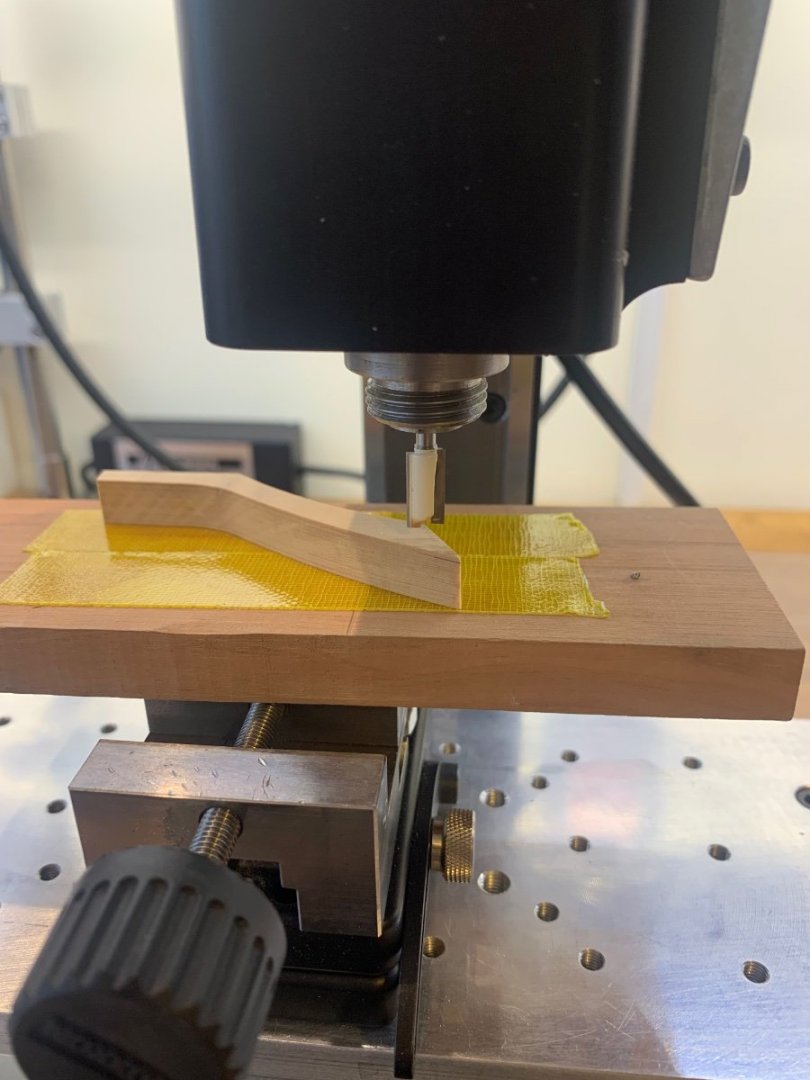
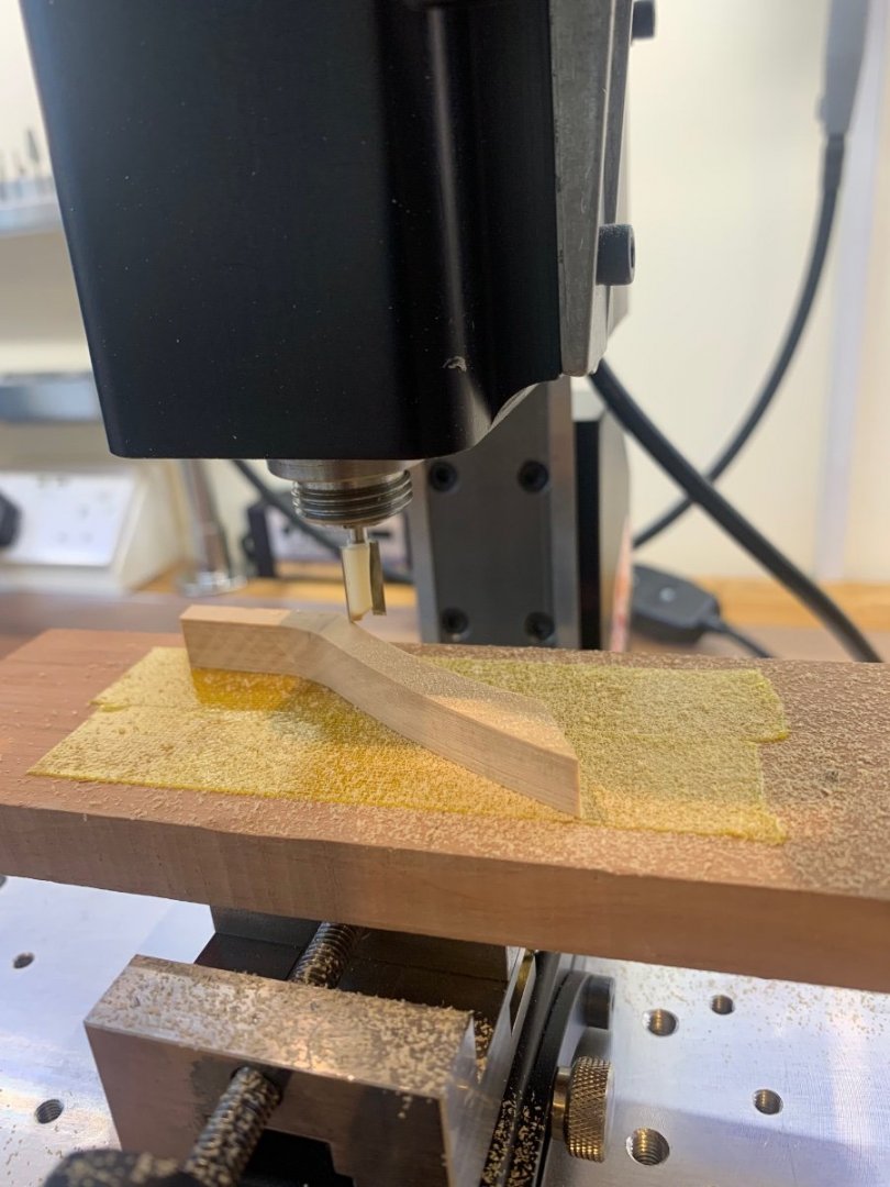
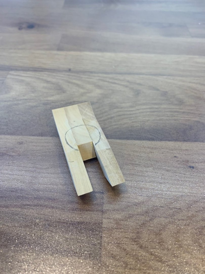
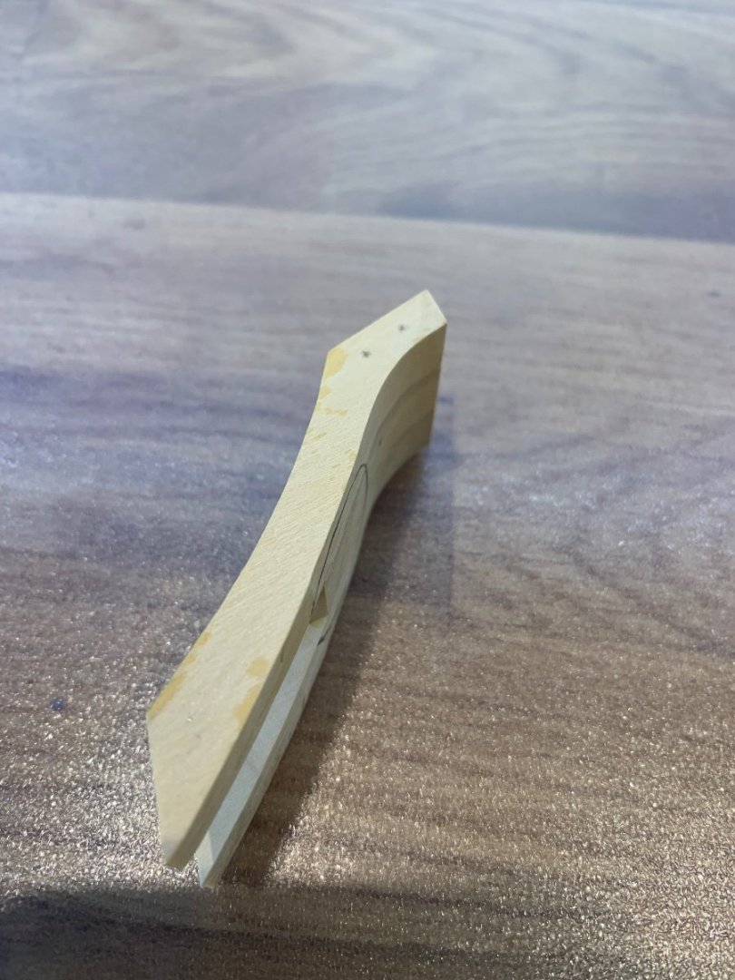
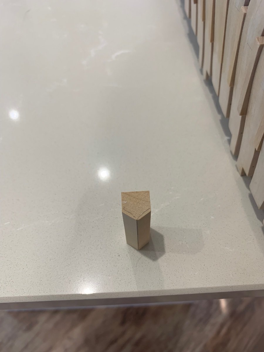
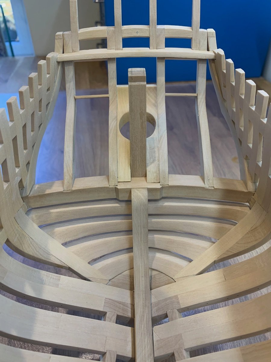
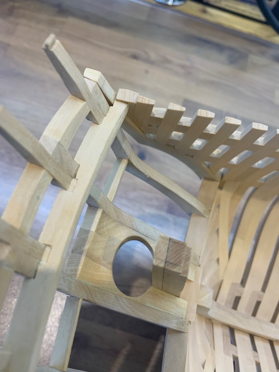
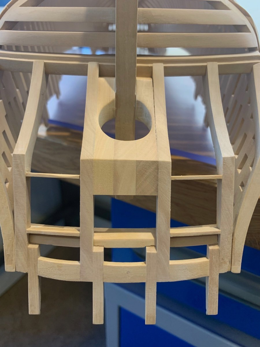
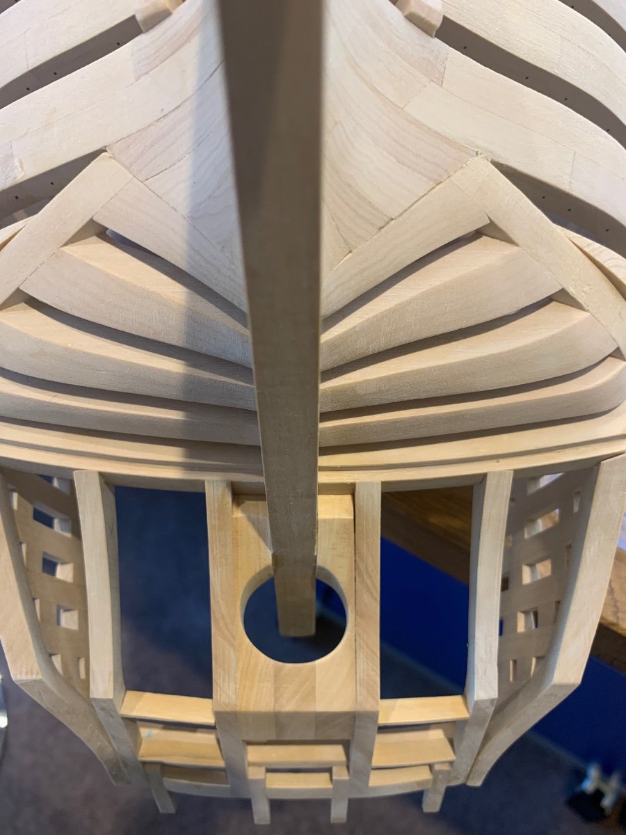
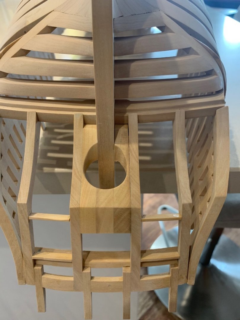
bitao, Greg and druxey thanks for the support and encouragement 👍 I honestly don't mind putting mistakes and problems that I have into this build as hopefully it will help another builder in the future. So onto the helm port - I really enjoyed making this part! I cut out the three parts required and discovered that one of my counter timbers is not quite vertical. So the first thing I did was to mill a slight taper onto the port leg so that it fitted correctly. Next I glued and pinned the parts together as I needed to get as much strength into this assembly as possible. The reason being was the cutting of the port hole. In Adrian Sorolla's book he glues these parts to the ship and then cuts the hole at a later date. This seemed like a very difficult thing to do considering its position, shape and angle. So I free handed a hole out on the mill which went ok and then finished it off with a file. I think I've saved myself one hell of a job later in the build. So my next job is to check the fairing inside the hull to make sure that I'm happy with it. I then need to strip down my jig to give me better access to the hull and I then want to mark out and make the deck clamp. Should be fun! Mark