


carlosgf
-
Posts
51 -
Joined
-
Last visited
Content Type
Profiles
Forums
Gallery
Events
Posts posted by carlosgf
-
-
-
-
-
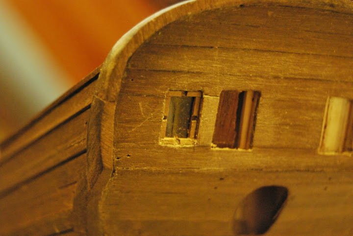
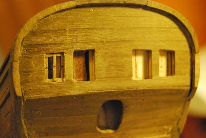
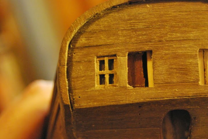
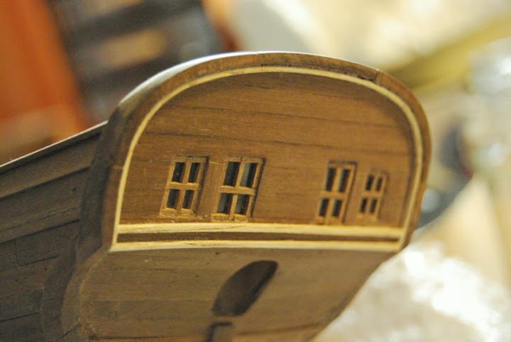
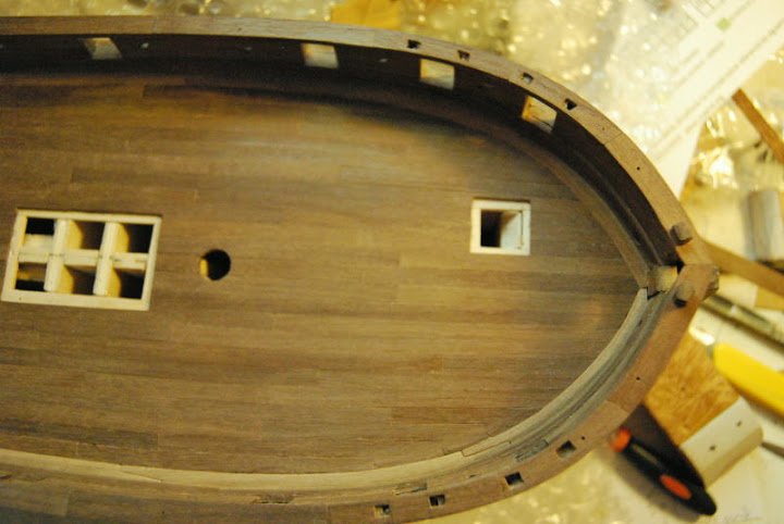
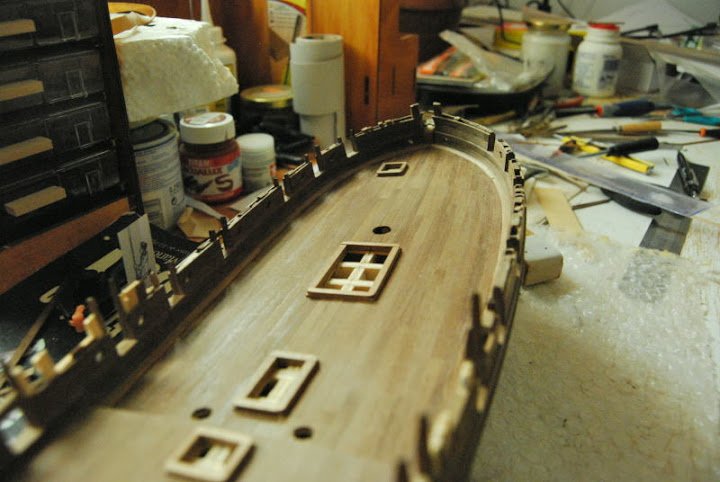
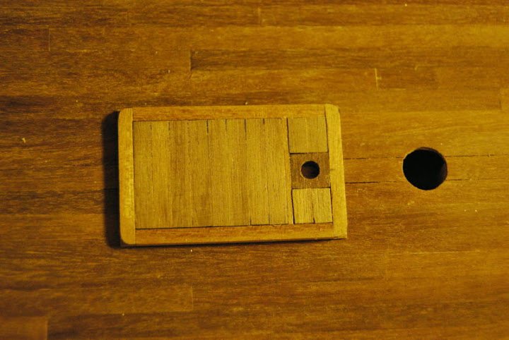
Hi all. Some progress:
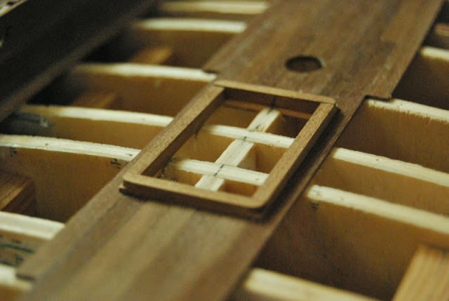
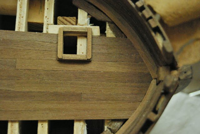
- Windows
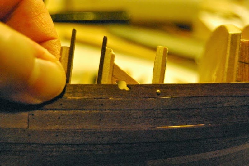
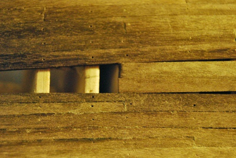
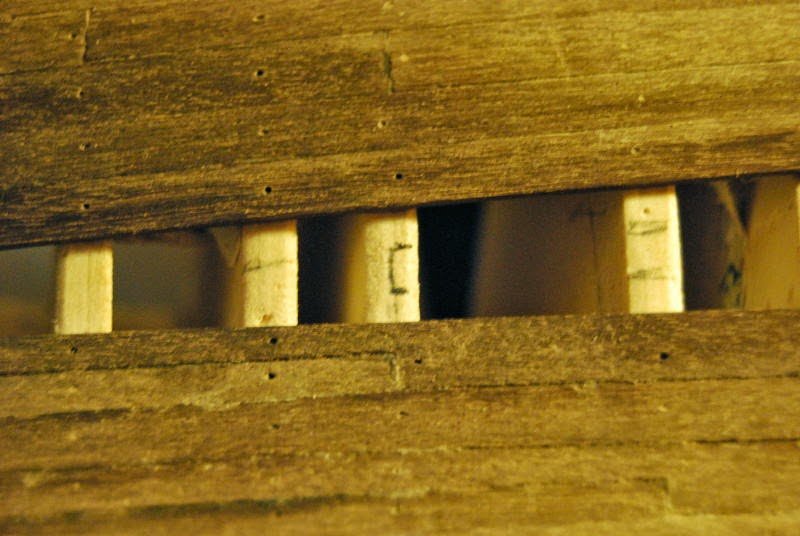
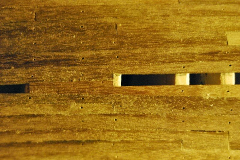
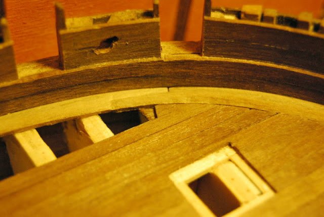
- Scuppers
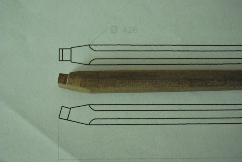
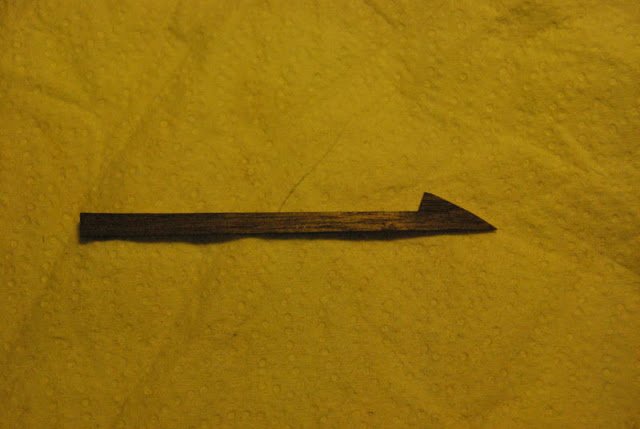
- rudder
Windows:
Scuppers: Are done in the waterway, very close to deck planking.
- hexnut, captainbob, russ and 2 others
-
 5
5
-
-
Thank you for your comments!!!!
 :)
:) -
-
-
-
Thanks for your comments!!!!
-
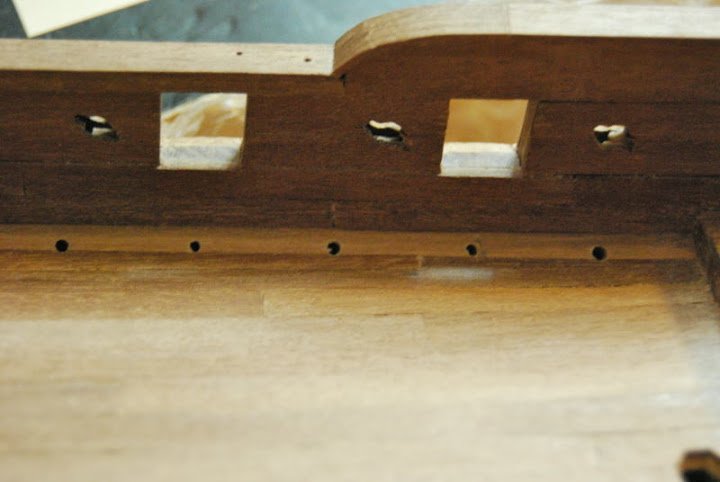
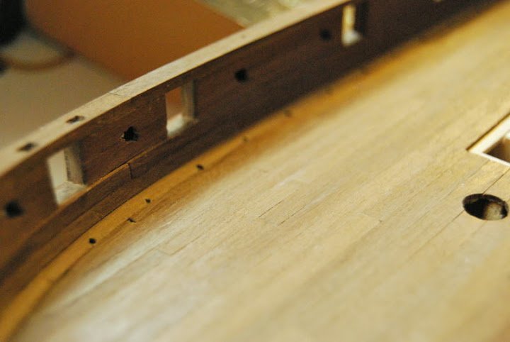
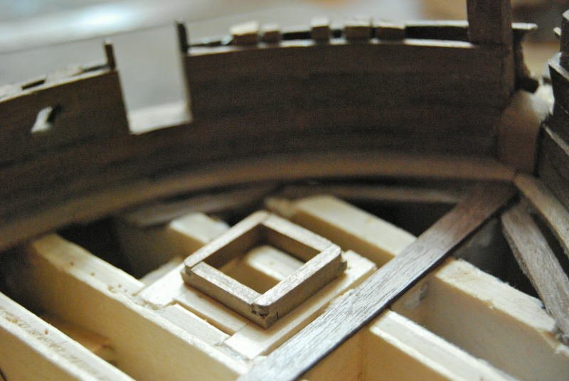
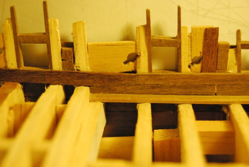
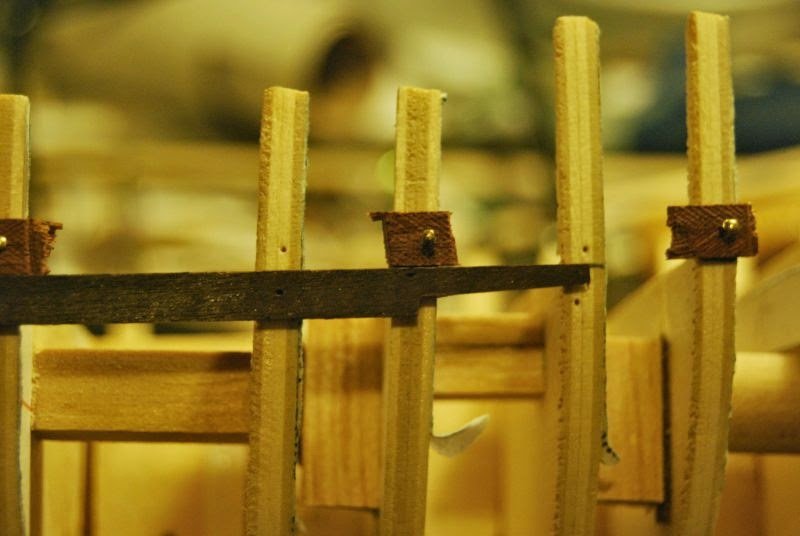
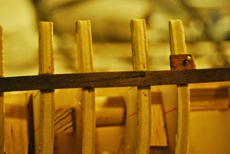
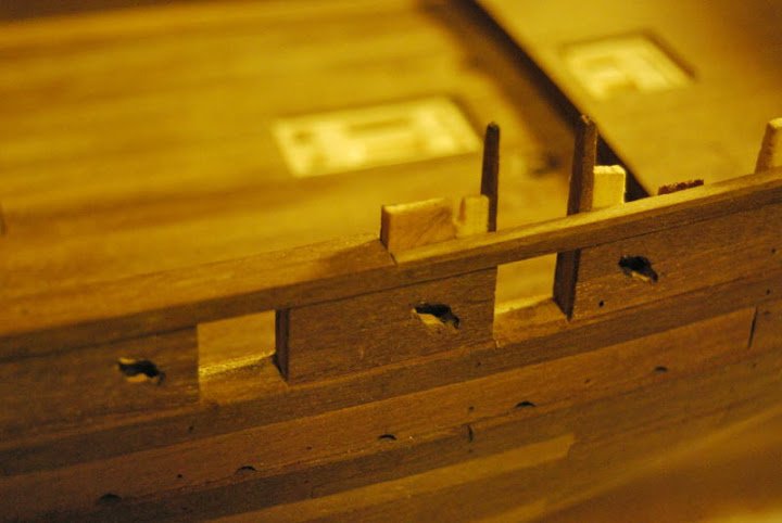
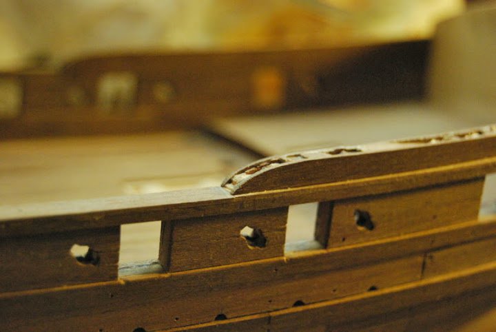
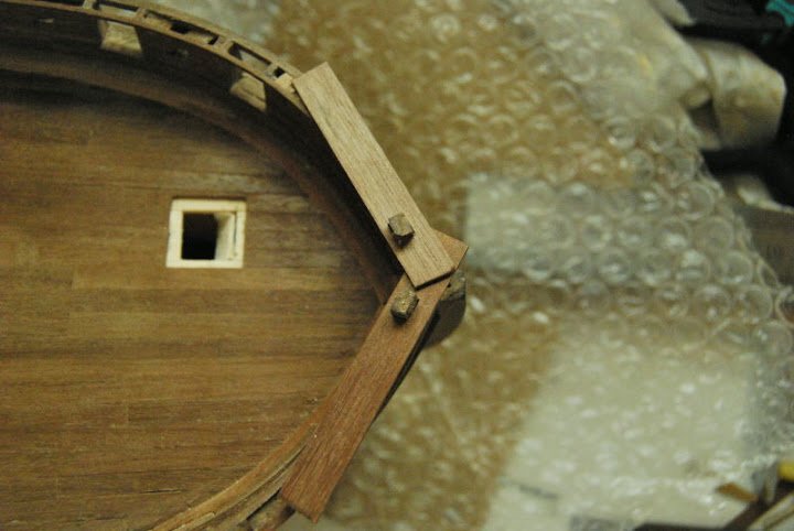
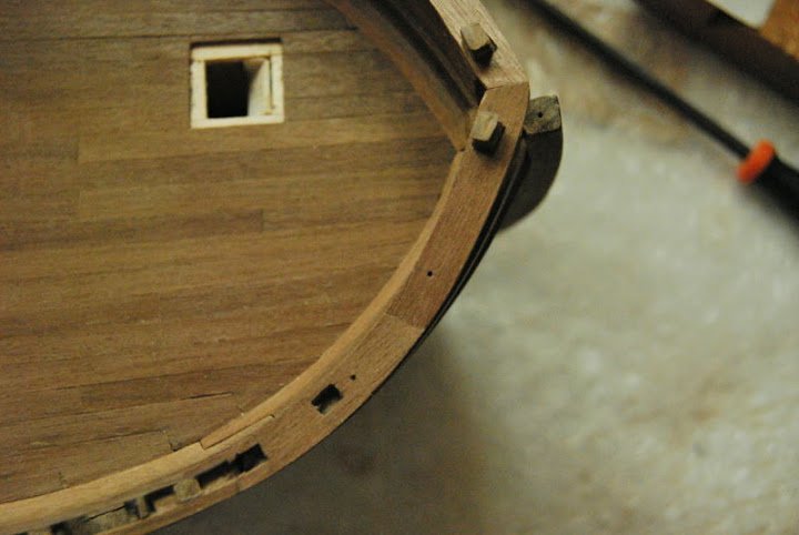
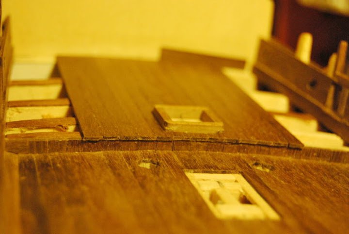
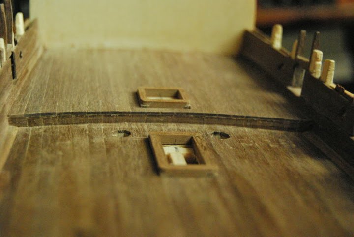
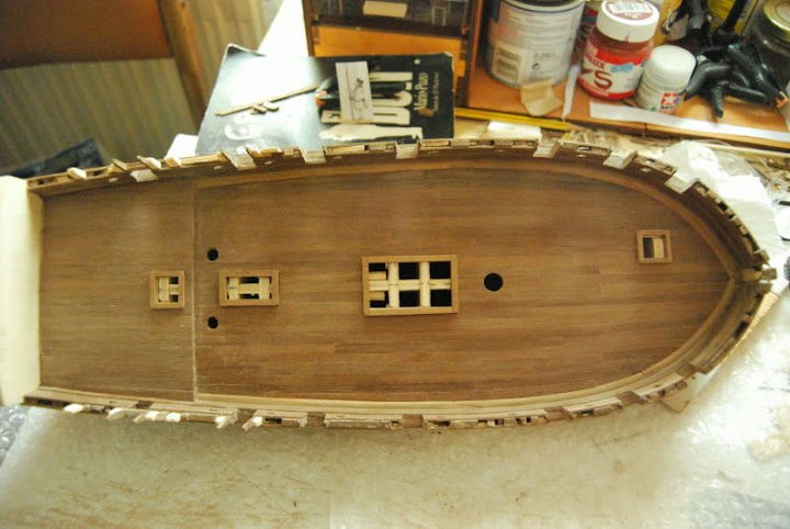
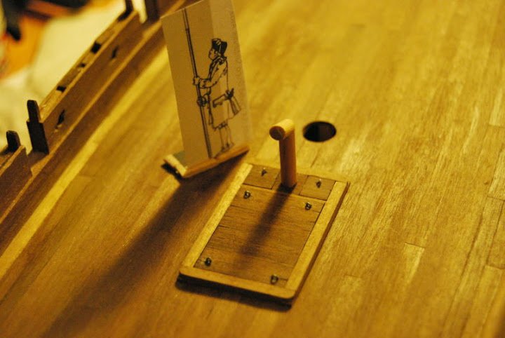
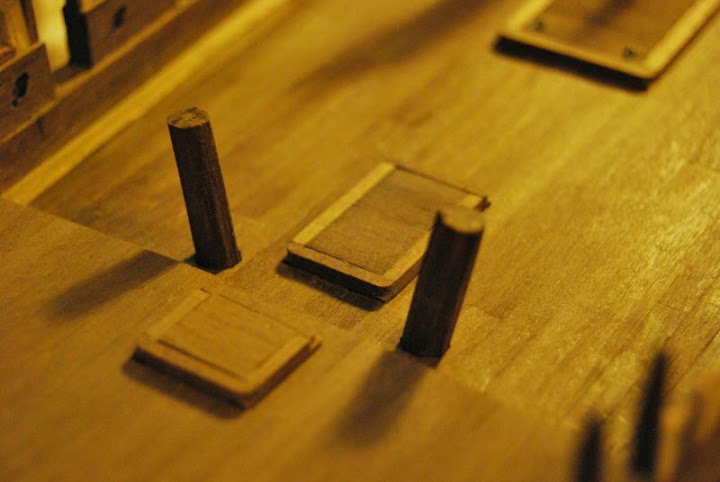
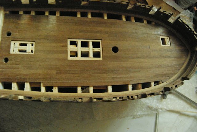
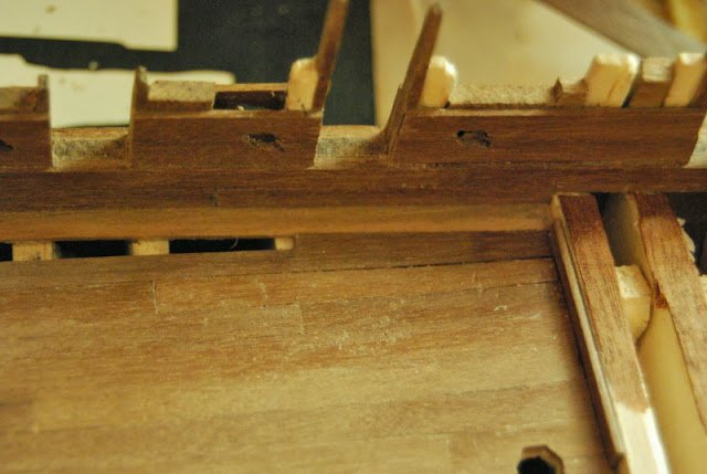
Hi all. A few progress:
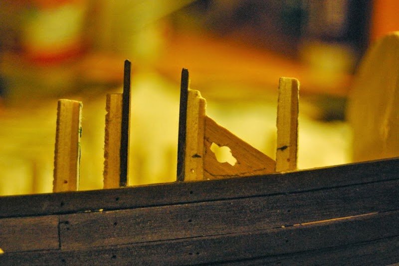
- fixed blocks in bulwark
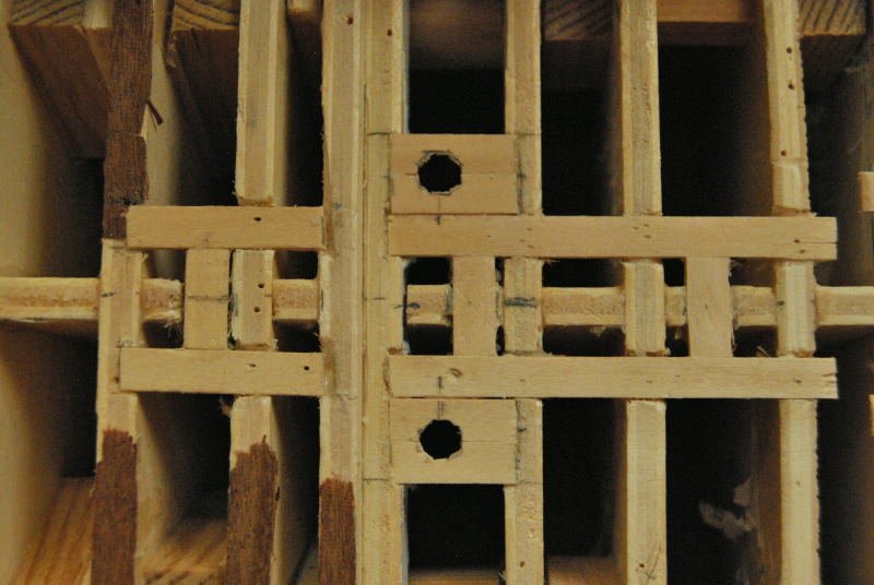
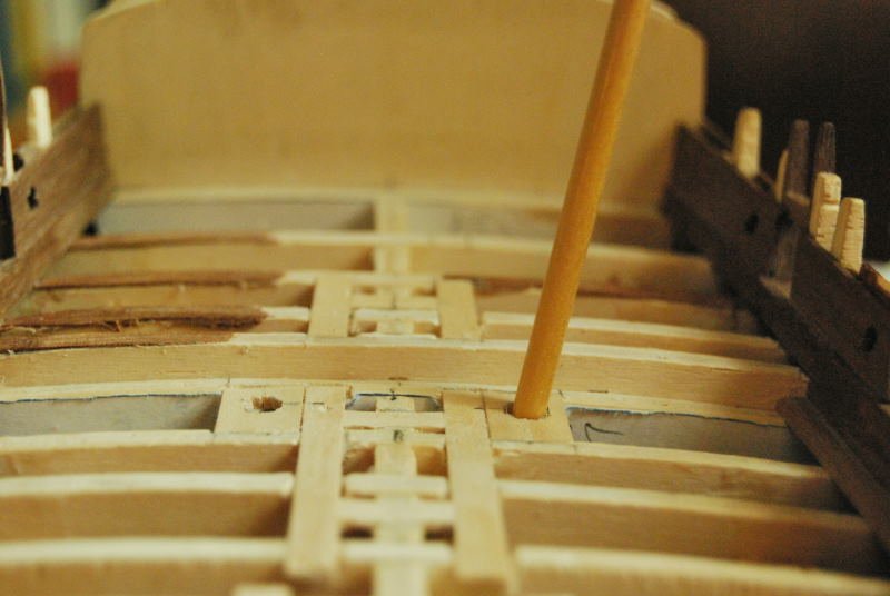
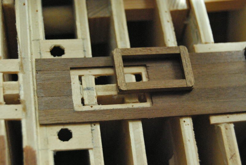
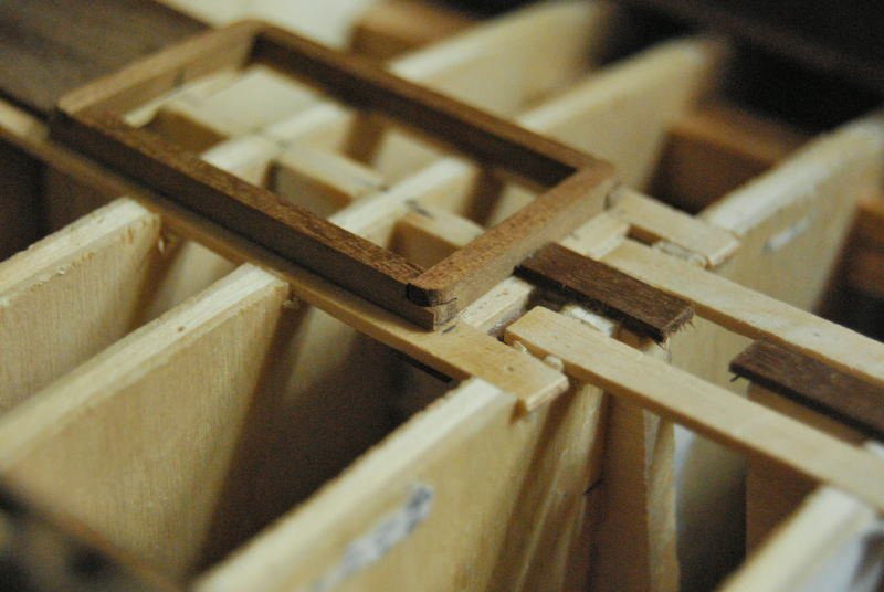
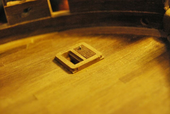
- reinforcement in the deck order to put the hatchways, scuttle and companionway.
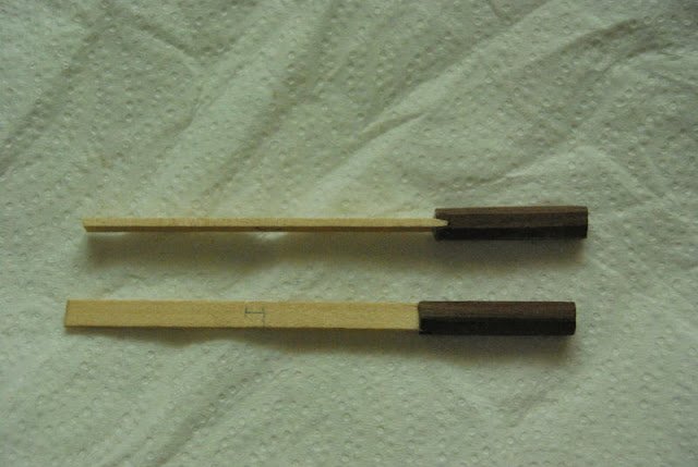
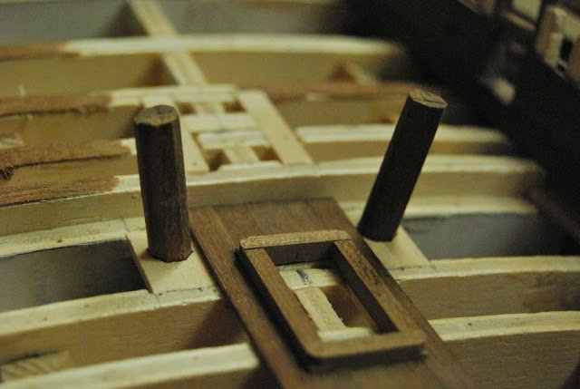
- holes fot the pumps (note that pumps are inclined, nor vertical)
- hatchway, main hatchway and scuttle
- begining og the deck
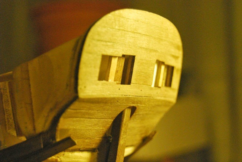
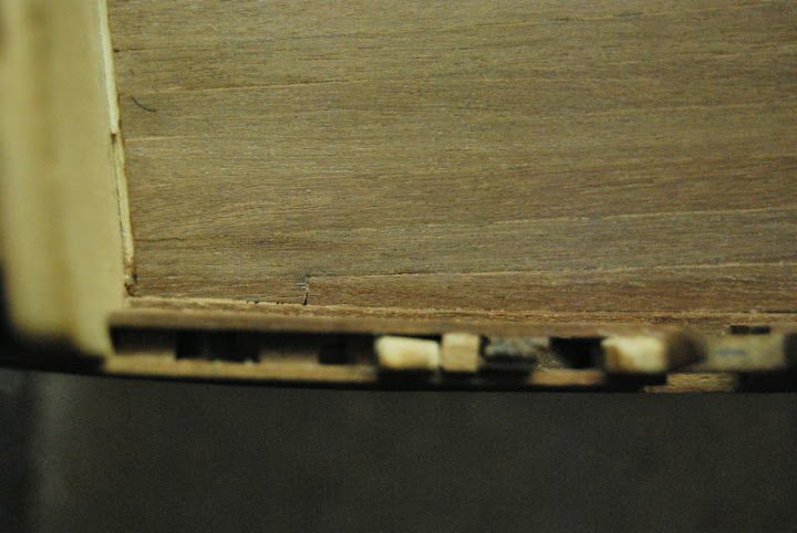
- hawse holes
-
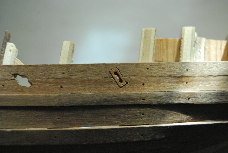
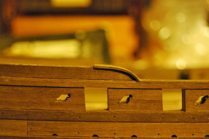
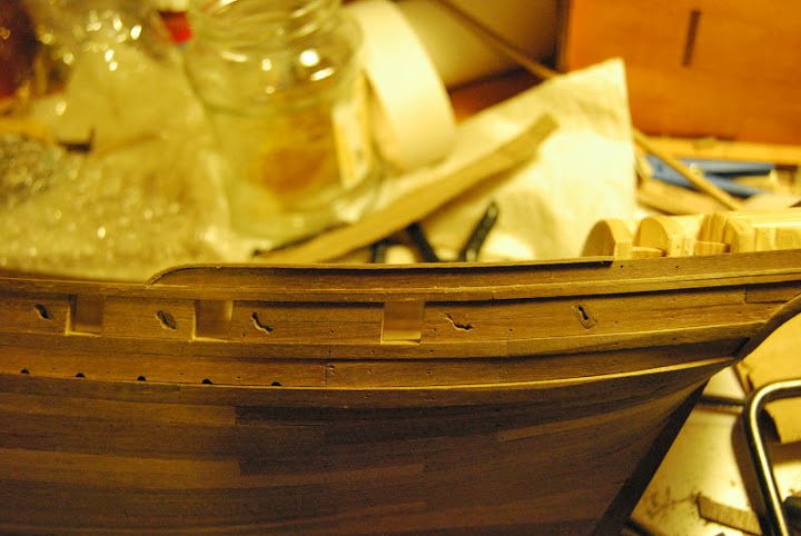
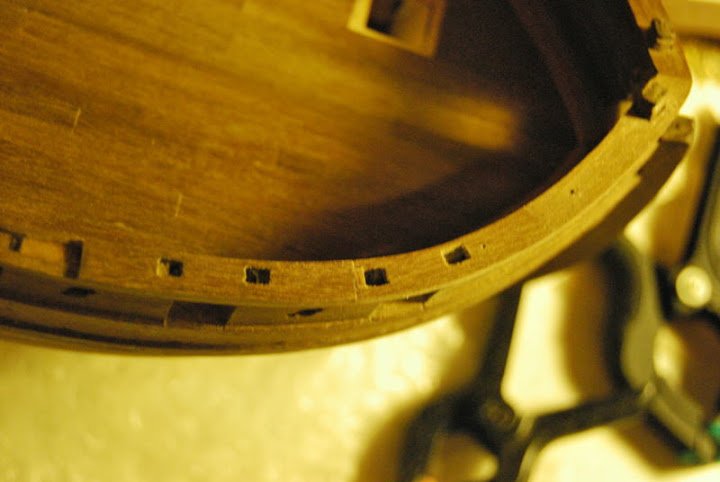
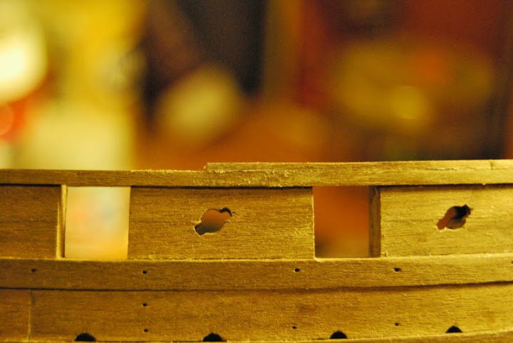
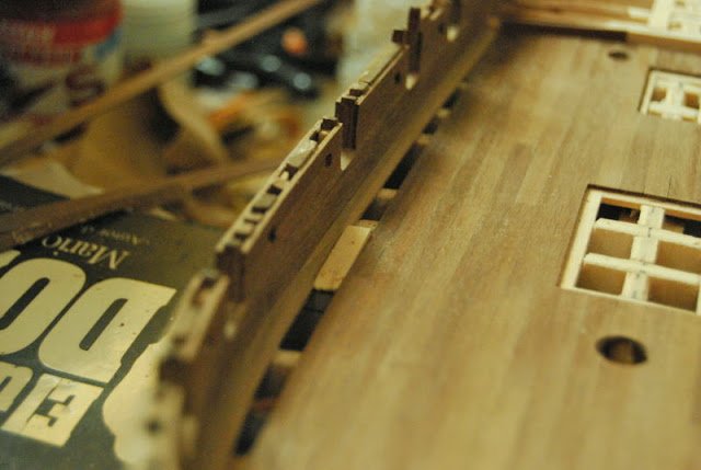
Hi, all...
After a relax months, I've continued with the Mediator. The things I made are:
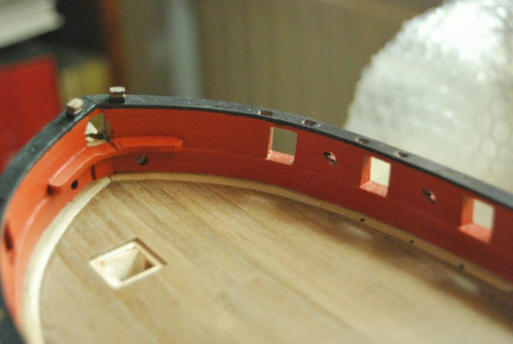
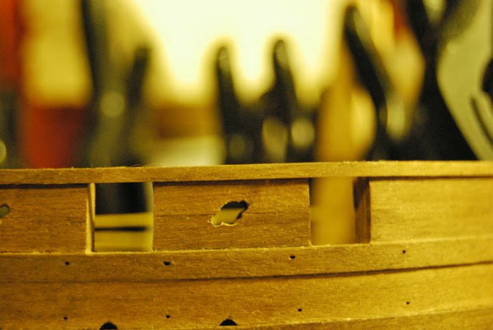
- gun ports
- sweep ports
- waterways
- spirketting
In addition, I made the plans for spars an mast. They are virtually the same of the Armed Virgina Sloop of Model Shipways, adapting sizes. I will not to include these plans to public release due to copyright restrictions.

- mtaylor, qwerty2008, NJQUACK and 5 others
-
8
-
In the forum Model Ship Builder you can find a very well done plans of the Mediator, including masts and rigging.
http://modelshipbuilder.com/page.php?192
Gene Bodnar's prototype:
http://modelshipbuilder.com/e107_plugins/forum/forum_viewtopic.php?18791
Jeff Staudts' model
http://modelshipbuilder.com/e107_plugins/forum/forum_viewtopic.php?19638
Jeff Staudts' plans set
http://modelshipbuilder.com/e107_images/custom/Sloop%20Mediator%20Plans.pdf
http://modelshipbuilder.com/e107_images/custom/Mediator%20Sloop%20Print%20Authorization.pdf -
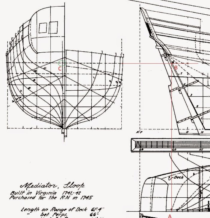
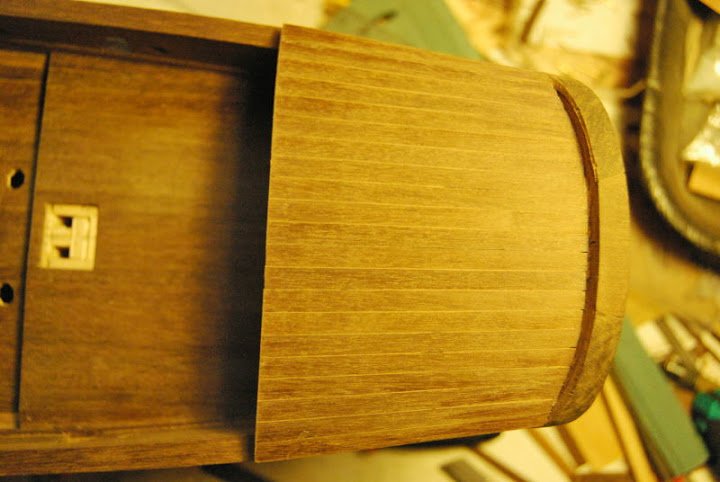
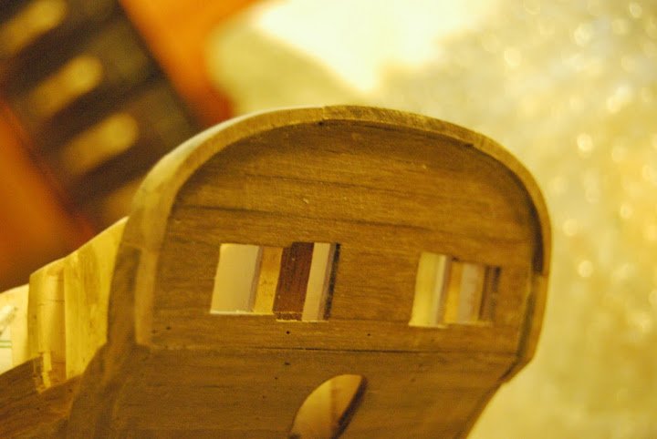
A question: what made you go with a rounded stern rather than a square tuck? most the other models I've seen of this vessel seem to have a square tuck stern in fact I have another set of POB plans for this ship showing a square stern, is this just a matter of preference? or based on historic data?. I'm wondering because I may build the Mediator (or simelar vessel) in 1:20 scale RC once I am done with my Byzantium.
Thanks.
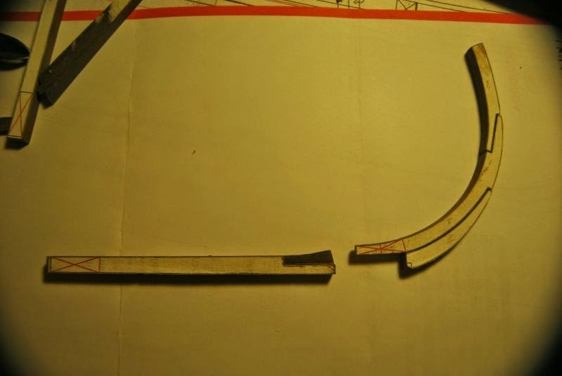
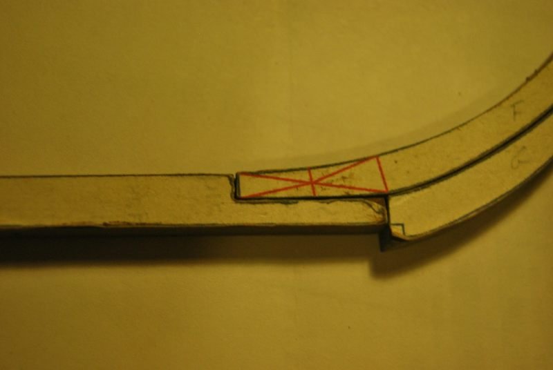
PS. Some of the drawings in the PDF aren't showing up properly such as the rudder which just shows up as the red lines for the table joint.
Lextin.
Hi, Lextin.
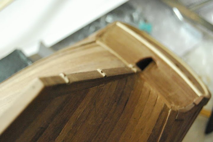
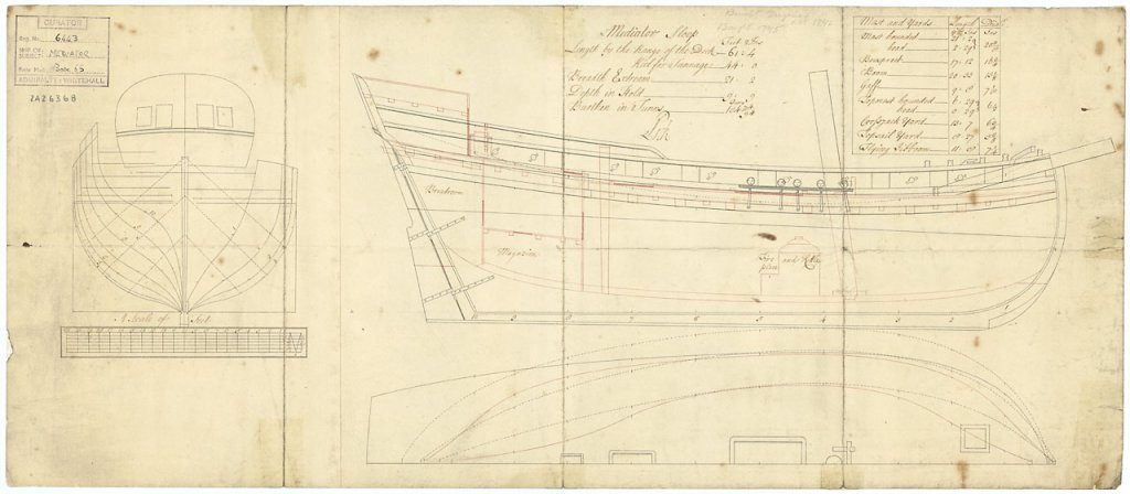
As you can see, The horizontal curve 6 ends in the rudder post exactly in the point marked as 'A'. Follow the vertical line until letter 'B'. If the plans of Chapelle are correct, at least in the points B or C, the surface is round. There is no indication about what happens over this point, but in my opinion, this point is too near of the transom and it's is not possible a square stern.
I have no probles with PDF file. Has someone else this problem? Do you have the last version of Acrobat Reader?
-
Thank all of you for the comments.
-
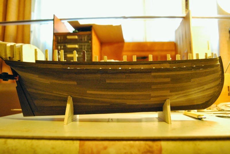
An this is the process of the sloop Mediator until now.
-
Thanks for your coments!!!
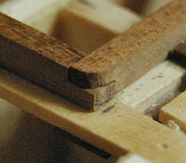
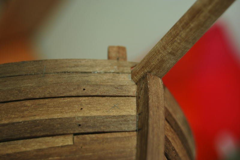
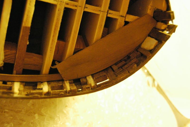
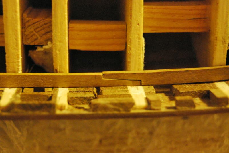
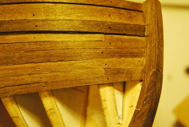
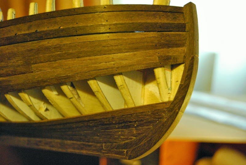
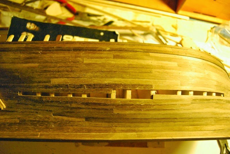
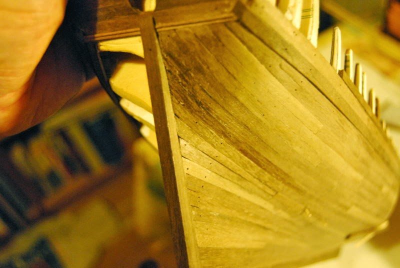
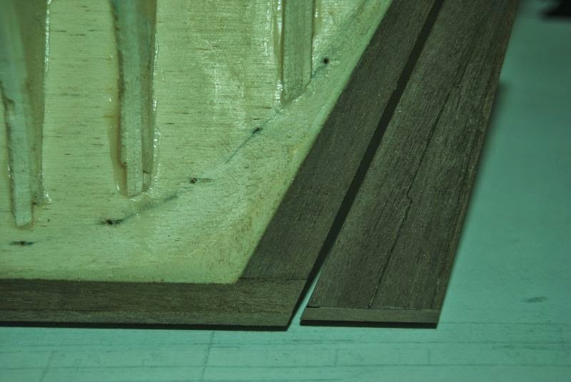
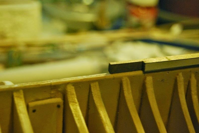
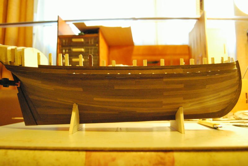
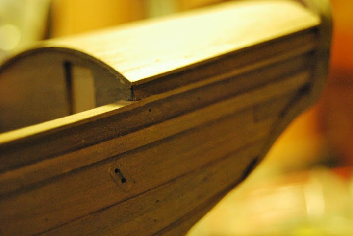
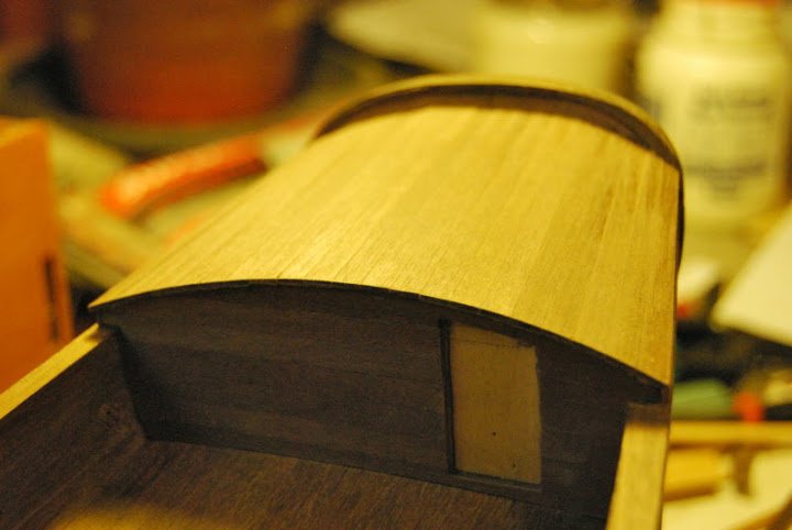
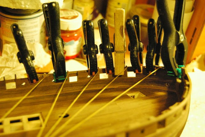
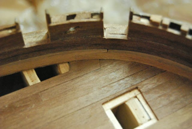
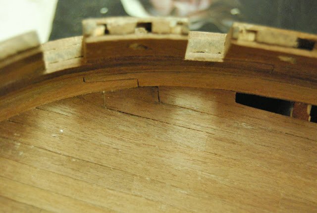
The planking of the hull begins with the wale. The main wale (the lower wale) dominates the position of the planking. I put strakes alternatively up and down, joinning in the center.
In the forum you can find manuals of how to make the planking of the hull. I strongly recommend you to read these manuals, The final look is better than the suggestions of some kits... and the time spent in this process is the same (more or less).
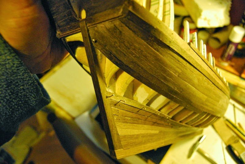
There is a reduction of distances fore an aft. The strakes should be reducted in the joining with the stem and stern. There are several methods (i've used both):
- to reduce the width of the strakes
- to make that a strake ends into another one or in the junction of two strakes.
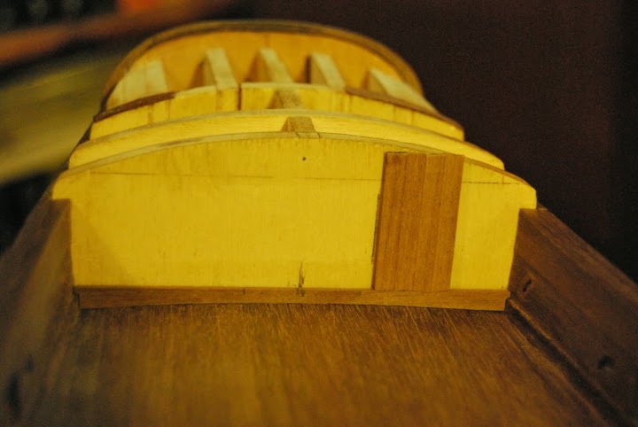
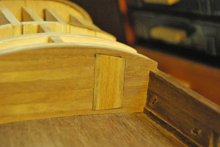
-
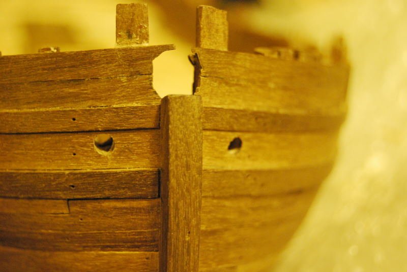
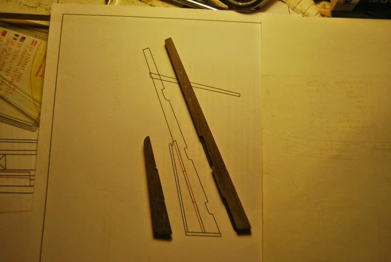
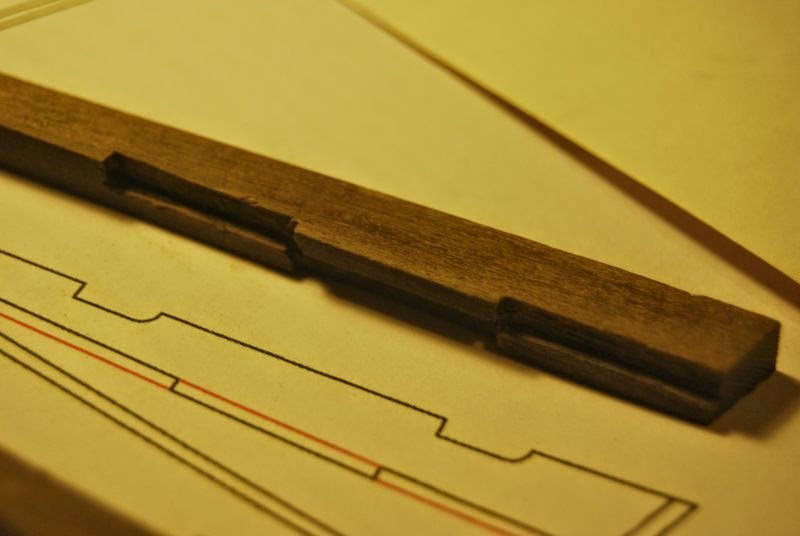
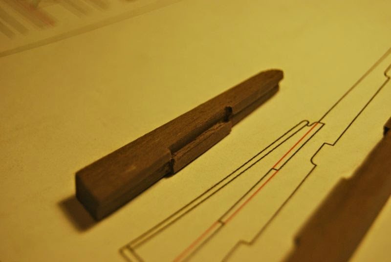
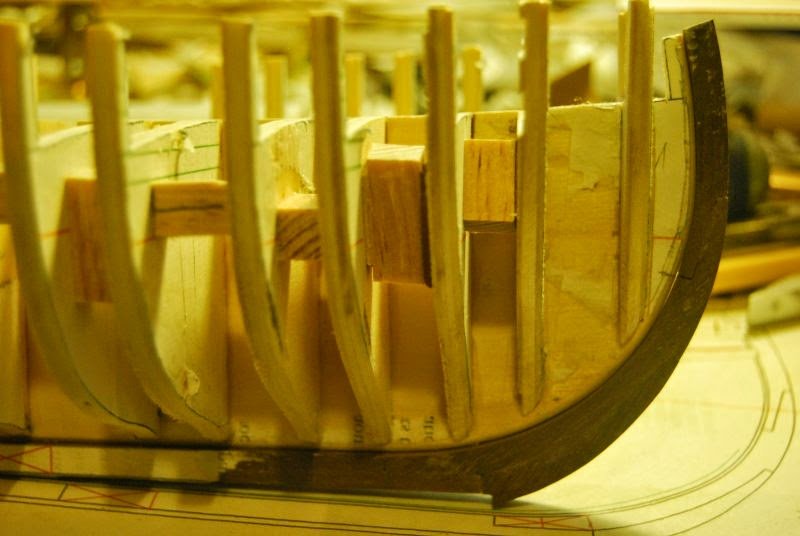
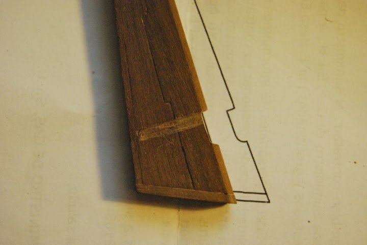
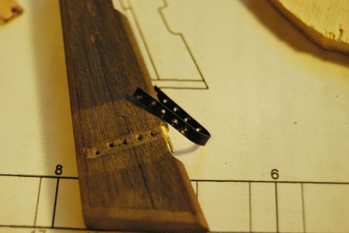
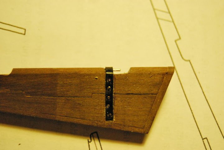
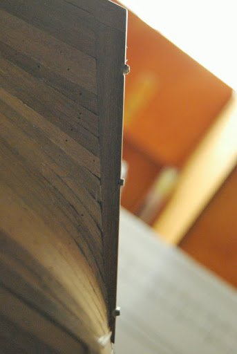
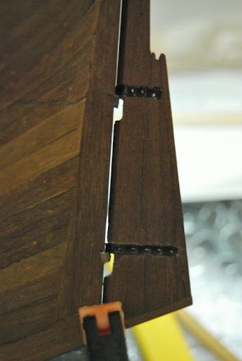
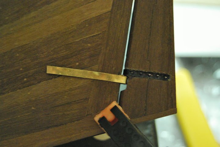
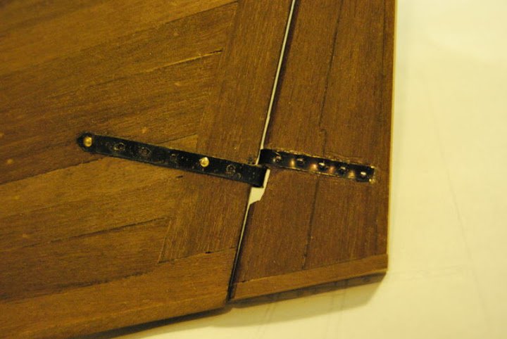
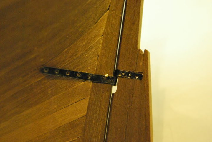
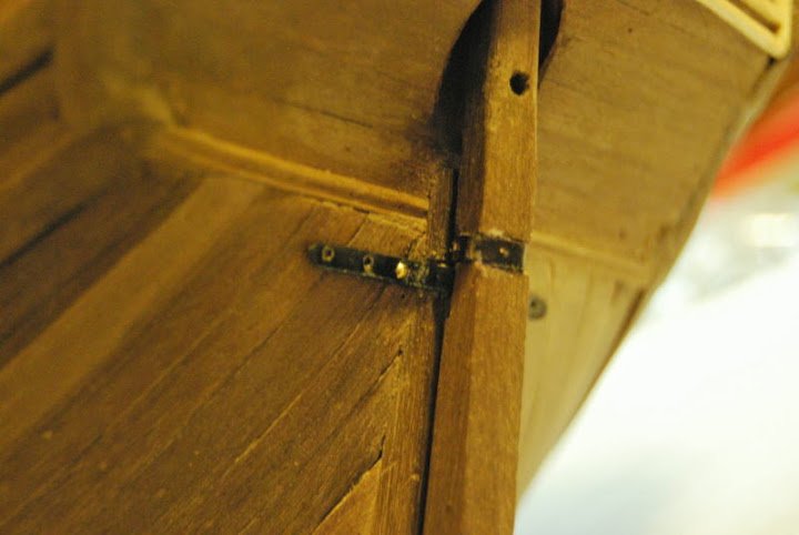
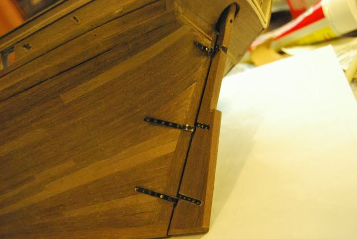
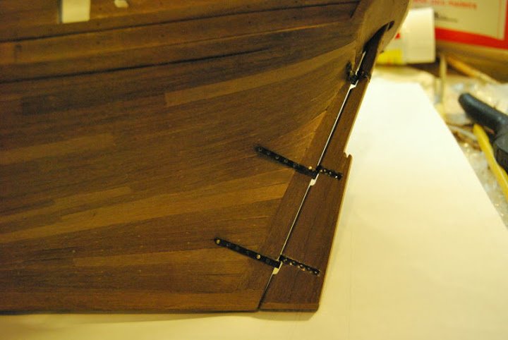
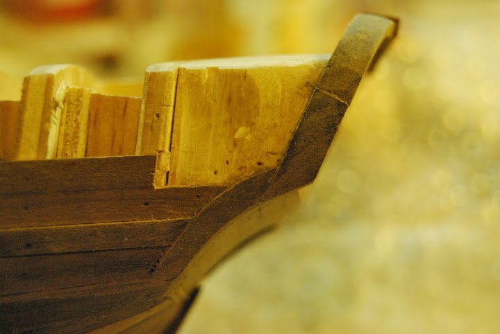
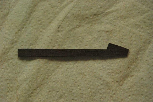
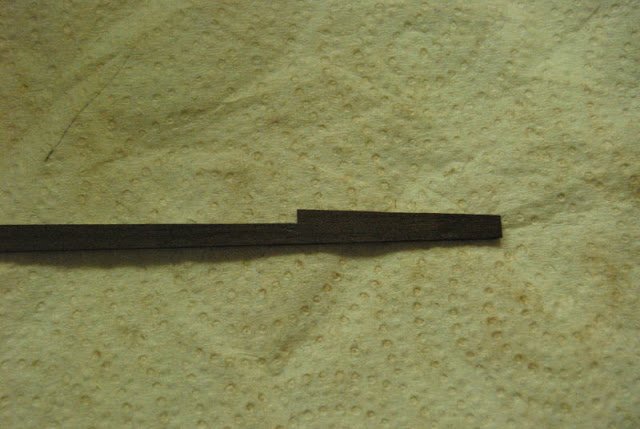
The rudder is made of two main pieces. I taked the idea form Swan Class Sloops of David Antscherl, considering that the Mediator is a very small ship.
- russ, aviaamator, Rudolf and 6 others
-
9
-
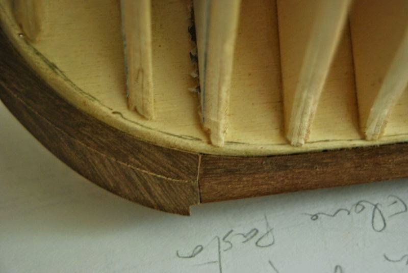
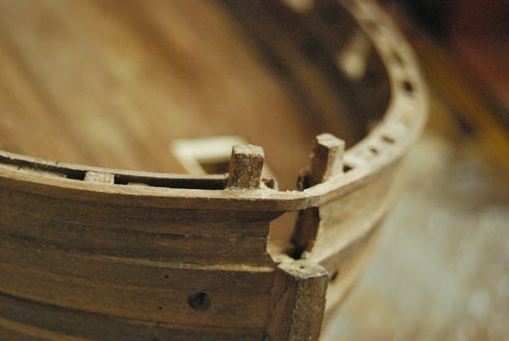
The stem, keel and rudder post are part of an interesting set. Unlike the kits solutions, I've tried to simulate a 'real' approximation.
I have a very few information about America Colonial ships. My assumption is to made this pieces in an English (Great Britain) way. I've made a mix of Cutter Alert (Peter Goodwin), Granado (Peter Goodwing) and Swan Class Sloop (David Antscherl).
- kees de mol, mtaylor, Mfelinger and 6 others
-
9
-
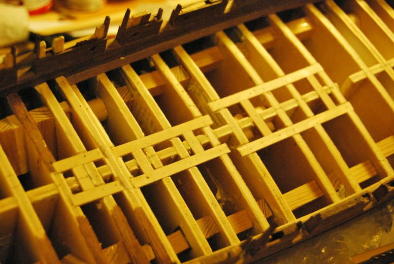
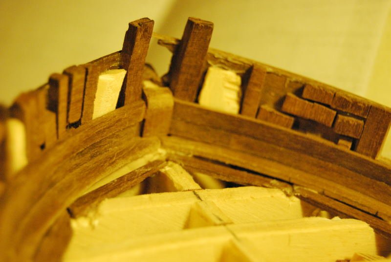
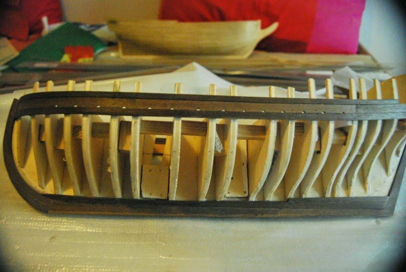
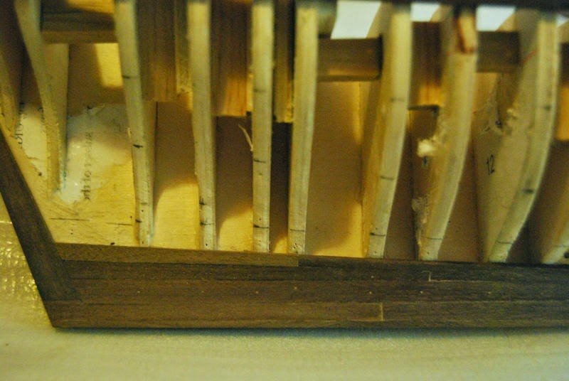
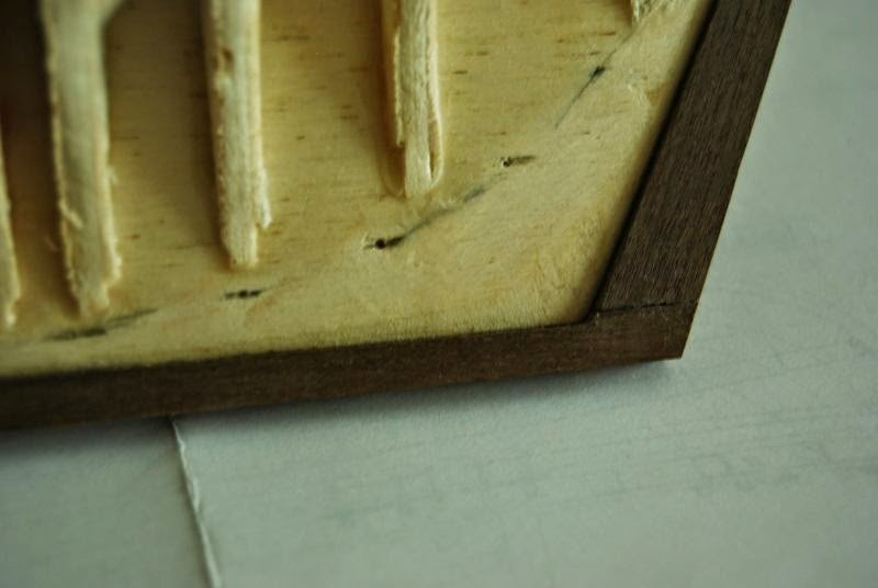
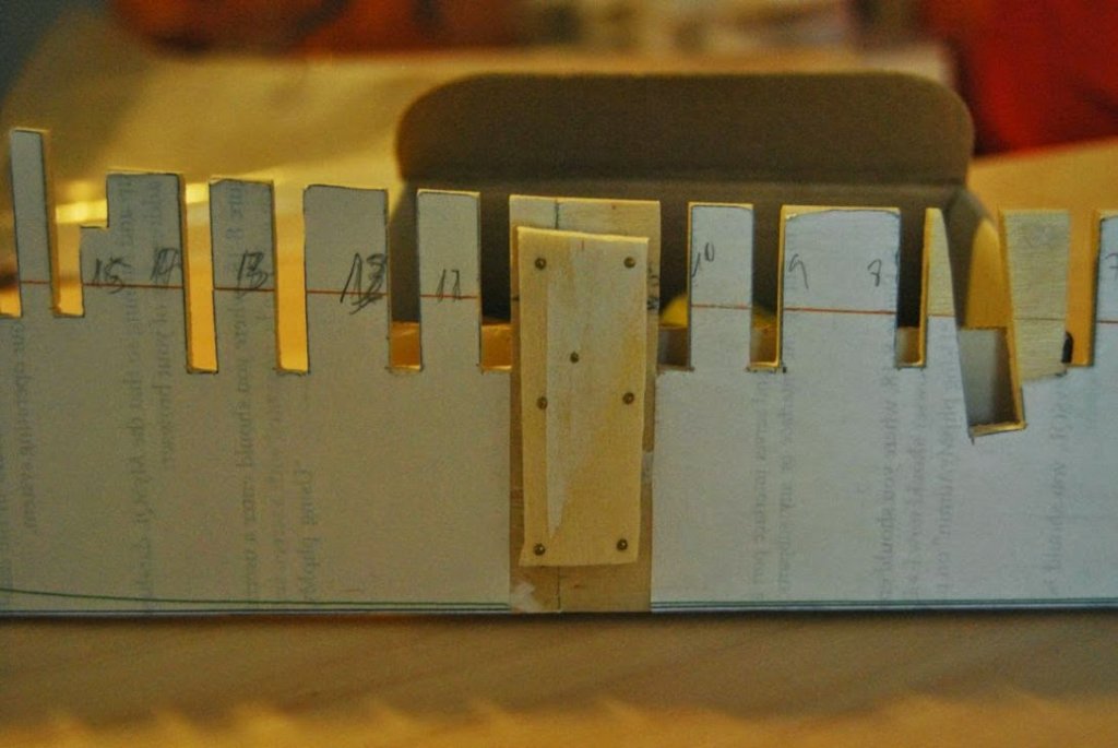
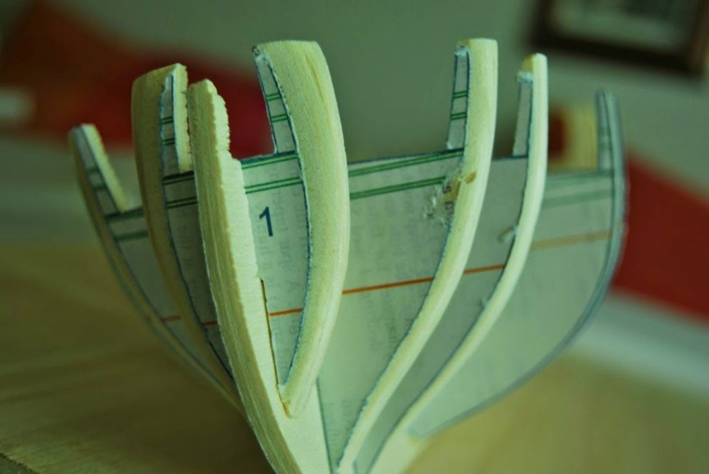
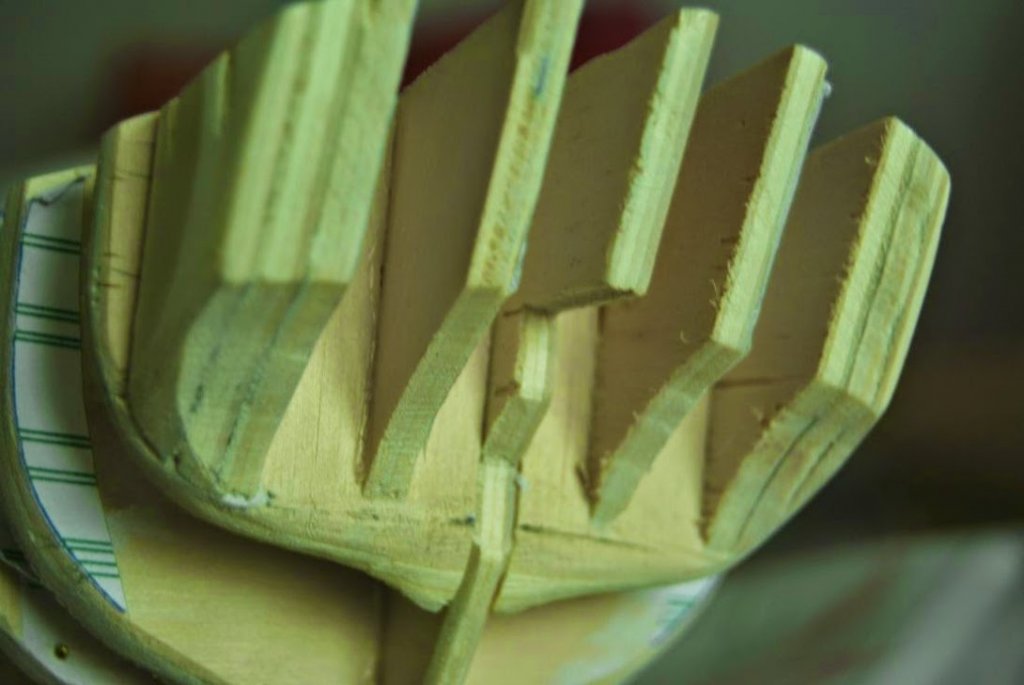
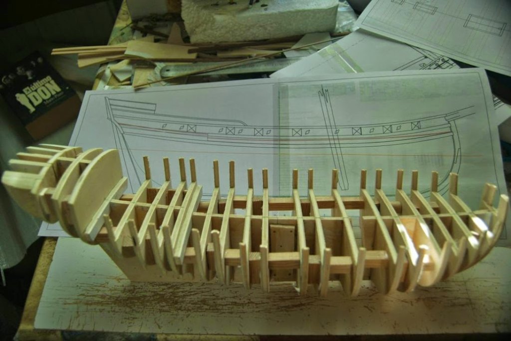
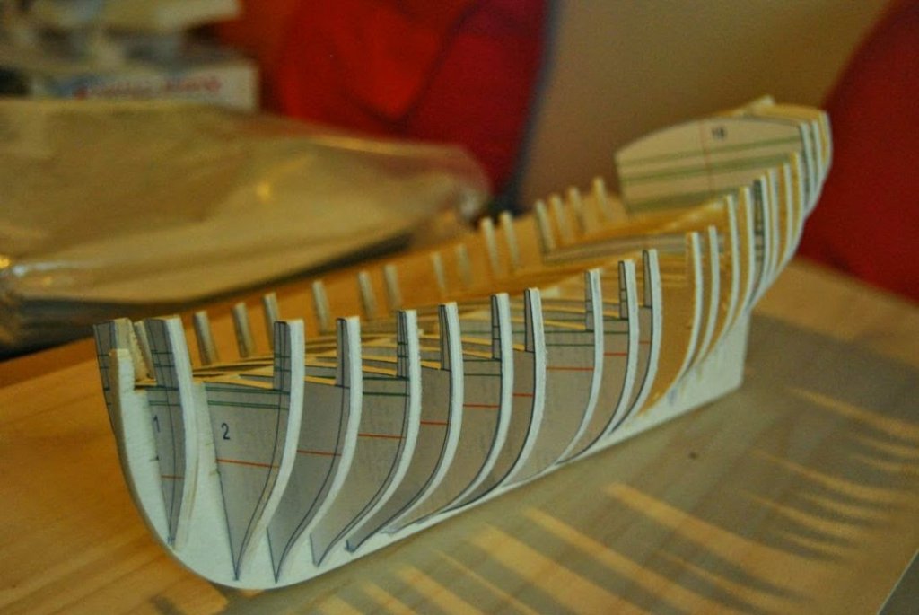
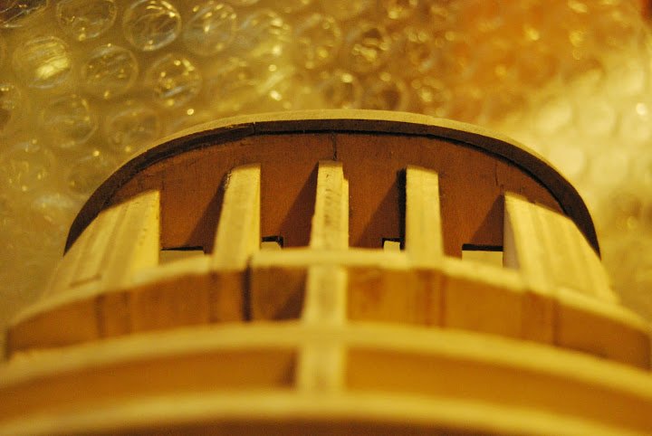
Bulkheads are glued to the false keel. This is made in two pieces because size considerations. Chocks (?) are glued between bulkeads to ensure the stiffness of the ship. The edges of the bulkheads are beveled order to facilitate the settlement of the strakes. These edges are drawn but the inner line is only valid if the thickness of the bulkheads is 5 mm (in other case, sand by eye).
- qwerty2008, Chuck, aviaamator and 6 others
-
9
-
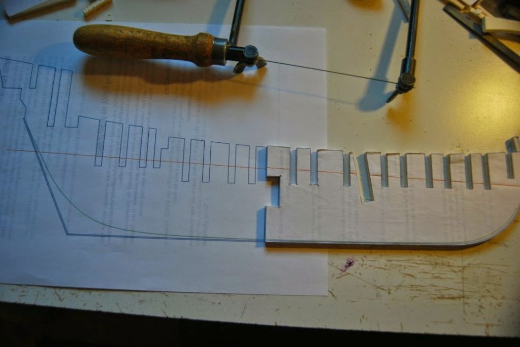
My idea was to make a plank-on-bulkhead ship model. The bulkheads and false keel were designed with Autocad. The drawings of Chapelle needed a lot of correctios because the small size of the drawing in the book, distortions of the paper, etc...
I put the plans in the first post and I will to update them if any change occurs. Please, feel free to use them, if You are interested in this model.
Some points:
- The bulkhead and false keel are designed to have a thickness of 5 mm (5 millimeters).
- Under the tramson, there is a rounded stern. I'v seem models wirh plain (square) stern.
-
The plans.
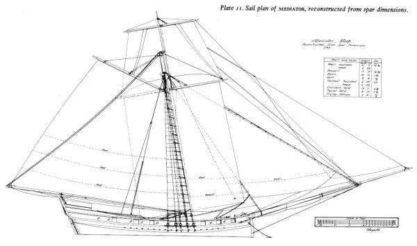
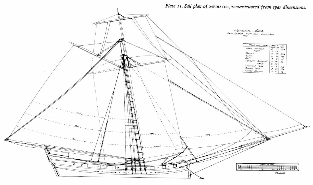
The plans i've used for the sloop Mediator are in the book 'The search for speed under sail, 1700-1855' written by Chapelle. I've scanned these plans and I've resized to scale 1:48, I think this is an interesting scale that allows to work with some detail.
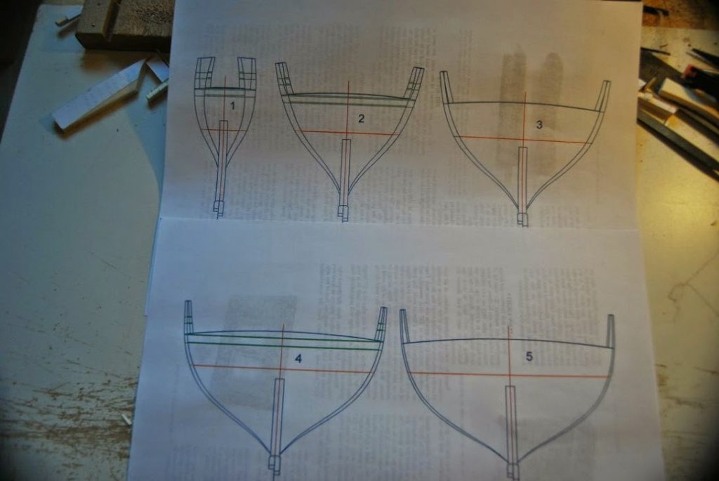
Chapelle's plans are two. The first of one is the hull drawings, waterlines, buttock lines, diagonals...
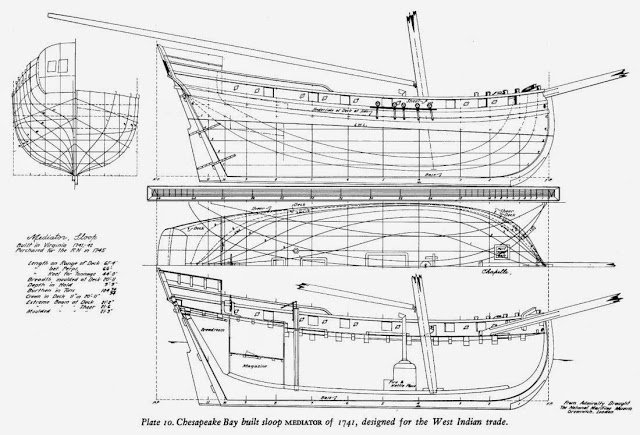
And the second one is the sail drawing.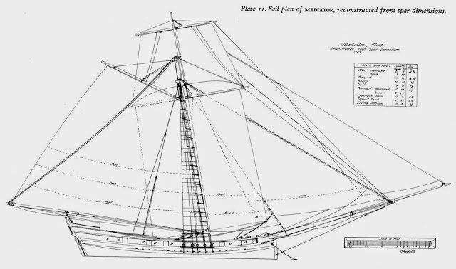
There is an original drawing taken in 1745.
I've started to work with Chapelle's drawings because i found these plans before.
- IgorSky, garywatt, qwerty2008 and 6 others
-
9
-
Hi world!
I want to show you my current ship model project: the sloop Mediator.
I found the plans of this ship in Howard I. Chapelle book named 'The search for speed under sail, 1700-1855'. I thought it would be an interesting ship for a first scratch work.
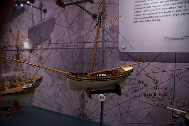
In the National Museum of American History, Washington, DC, there is a ship model of the Mediator:
http://etc.usf.edu/clippix/picture/the-mediator.html
And it is my ship model today:
Please, let me to show slooooowly the building process step by step.
P.S: Apologizes to everyone for my awful English.
P.P.S: I put my drawings in this first post. I'll update if any change happens.
P.P.S: Add a direct link to all photographs I have about the Mediator buid:
https://picasaweb.google.com/113346618105593843079/6058494423241948545?authuser=0&feat=directlink
- Landlubber Mike, qwerty2008, russ and 8 others
-
11
-
Hi.
Howard Irwing Chapelle in his book 'The search for speed under sail 1700-1855' shows the Mediator sloop (pages 70-73). This ship was built in 1741. It is not exactly a cutter but it is and American cousin. The original plans name a jibboom with its sizes. Chapelle interpret the planes and shows a picture with the sails.
http://prints.rmg.co.uk/art/491163/mediator-1745
The kit Virgina Sloop of model shipways is quite similar.
I hope this hepls you.
Carlos.


Mediator 1741 by carlosgf - Scale 1:48 - Howard I. Chapelle's version
in - Build logs for subjects built 1501 - 1750
Posted
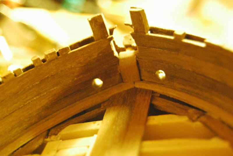
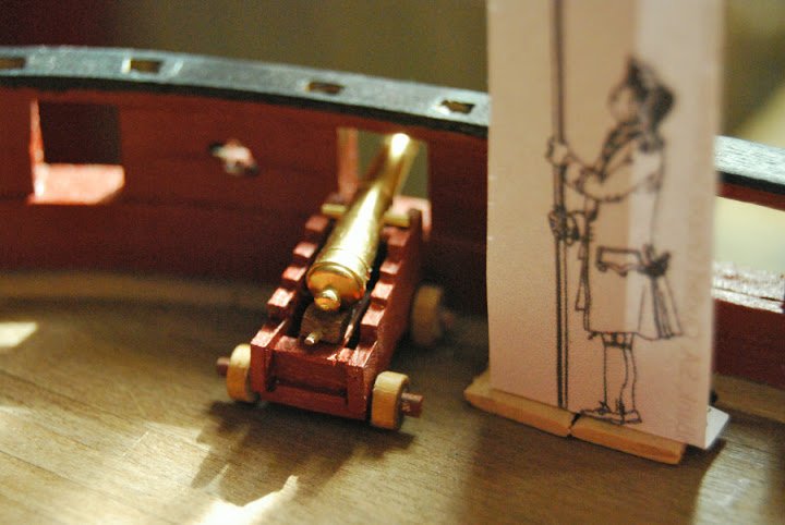
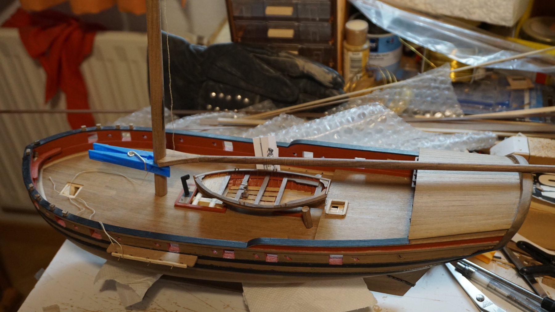
Hi all some progress:
- a breast hook
- adding somoe color (unfinished)
- the pedestal
- channels
- range cleats