

.jpg.f26acc9a74319261612561bfa7da1303.jpg)
vaddoc
-
Posts
1,521 -
Joined
-
Last visited
Content Type
Profiles
Forums
Gallery
Events
Everything posted by vaddoc
-
.thumb.jpg.6fd4c1b78768bb3efd745ab810936005.jpg) I ve been following all your paper builds Danny.. Mighty nice! And mighty small...
I ve been following all your paper builds Danny.. Mighty nice! And mighty small... -
I have a tin pot where all sharp things go upside down. Also a small cardboard box for drilling and cutting related stuff, one for general stuff, one for sanding related stuff, one for rope making and so on...An organised chaos but tidying up is quick and when looking for something I know where to broadly look. Of course from time to time I do lose things that resurface later on.
-
You are having too much fun GL! Lovely boat, I like the colour combination a lot. Looking forward for the rest of the journey Vaddoc
-
Very nice work on the rabbet, I guess your chisels are razor sharp! Very crisp edges, I always struggle and end up with wider margins and irregular surfaces.
-
Good news! No need for concern, the plank shape and run is fine! The computer can unroll a curved surface to give the straight surface it originated from, very useful when it comes to planks. The shapes I got were odd, and despite what the software was saying, eyeballing the hull they did not make sense. The problem was that really, CAD is very unforgiving. The hull is curved and fair but the planks are flat. I divided the hull to planks widths and asked it to unroll but this sections were curved and hollowed along their width, following the contour of the hull and not flat. This led to funny inaccurate shapes! I created a random sheer plank but made it flat this time. The result was much closer to what I expected. The plank blank now needs to be 39 cm wide which is much more feasible. Another interesting snapshot is the following, comparing my frames and sheer to the plans as given. The sheer is spot on as well as the aft frames. Note frame No 1 is identical and frame 2 and (to a lesser degree) frame 3 quite a bit different due to the errors and difficulties we discussed above. So all is good, the only minor loose end left is actually building the boat.😁 Putting all sort of disclaimers on accuracy of lofting etc, if any of you have an interest to build this boat let me know, I am happy to share these plans. Regards Vaddoc
.thumb.png.8e8b35ae3ae878d2eced8fc63242ab53.png)
.thumb.png.c6ef503dfe49d8e2e894bce3cd6b3e36.png)
.thumb.png.c260f544602cf5d00430a48c6cac4420.png)
.thumb.png.deb3c7277f382e7767e6ef7cfd532b3e.png)
-
Now I played a bit with the planking and odd shape planks come out. So odd that I now have two questions: 1. Can all boat shapes be planked? 2. For these period long boats (7 m long!), is it always one piece plank or is it common practice to scarf planks? There are other boats 35 ft long which is 11 m, so these cannot be one piece plank. The reason is that the initial tries show planks very curved at the transom end, which would need 50 cm wide blanks to come from and would have the grain running almost vertically at the aft end. This seems to happen because the hull at mid sheer runs vertically down wards before turning towards the midline and there is a pronounced curve of the sheer at each end. Looking at the NMM drawing this is indeed how the boat is drawn. More headscratching needed!
-
Druxey, indeed! GL, it is really not that difficult. Get any CAD, draw a dot, then another one, then connect these with a line. You 're off to a good start! The rest is improving on this! Keith, I actually do have access to a massive CNC mill but it feels a bit like cheating! I would sure like a bench top milling machine though! Bob, you are very correct, CAD (Rhino, well spotted) is very unforgiving and indeed this degree of accuracy is not necessary. I am aware that when actually cutting the wood the tolerances will be just horrible in CAD terms, nothing that sand paper or filler cannot fix. This however is a small boat so it was feasible to get all lines to work together. These guys of old, cutting wood without power tools and following some drawings where even one copy was not identical to the other...but I read that it was not unusual for ships to be a bit asymmetrical! In the end of the day, the ship has to be built! The picture you paint I think was their reality. Now I was indeed tempted to draw the planks, which would be a lot of work being a lapstrake. It is unnecessary though as I ll do the planking the old fashioned way but I will divide the hull just to get a nice run of the planks. I ll post this images later on I actually have in a couple of weeks another few days of computer time, I might be tempted to loft another boat or even something a bit larger. I ll have a look through the NMM plans. Regards Vaddoc
-
Live steam Bagnall loco and other railway stuff
vaddoc replied to michael mott's topic in Non-ship/categorised builds
Just went through the log Michael. I was left speechless. Wonderful work! I am clueless in this area but could I ask, how are all this moving parts kept lubricated? There are no sealed ball bearings, just metal on metal. I presume there were no ball bearings in the real thing either. -
Well, two new things to announce. First that the hull is finished. Secondly, I discovered another mistake! This one was in front of my eyes since the beginning. Simply, the body plan lines are indeed to the inside of the skin, but all other lines are to the outside! This is dead obvious looking at the drawing. What a mess! I have drafted all lines to the inside of the skin. Still, with a plank thickness of 2 cm (so that in 1:10 would be 2 mm), the error is not significant but could explain why I had such difficulties to get the hull to work. Still, lofting the profile view to the inside of the skin instead of the outside, creates some unique new problems that I had to overcome. I will try to explain these with some images. As I have defined the inner skin, I can easily get the shape of the frames at any position. What is left is the rabbet line at the keel, the stem and sternpost. To get this line, the outer skin is needed. This was very easy to get by asking the computer to offset the inner skin by 20 mm which is the plank thickness. Now, the rabbet line (the line the outer skin meets the keel) should be horizontal at the keel. The reason is that this line is given straight and the lofting is done on this basis. But I lofted considering that the bearding line (the line the inner skin meets the keel) was straight. So the skin pivots against the bearding line and the rabbet came out curved in two planes. The next snapshots show the problem. This is the face view of the two skins, the keel area is magnified in the second snapshot Nothing I can do for the bend downwards. To level things off however, the keel surface needs to come out and meet the outer skin. So I trimmed all lines to the same level. No idea how this will work when planking but the difference is about a mm or so. I think it will be fine. In profile view, the rabbet takes a small dive but it should not be visible. The black line is horizontal and the red line is the rabbet After this there is not a lot really to do. I projected the part of the transom that meets the planking just to see the bevels and the shape of the sternpost. There should not be a need to fair the frames at all as all the bevels will be known and cut in advance. Joining the two halves with a keel 80 mm wide gives us the final boat shape with the inner and outer skins I now need to decide whether I will use steam bent ribs or solid frames. The position of the temporary molds for the lapstrake planking will be such that the same screw holes would be used for the molds and the permanent frames. I would like to leave the planks unpainted so no rogue holes allowed. This might change though. What is needed now is to finalise the shape of the stem and the transom and to figure out the positions and shapes of the frames and subsequently the positions and shapes of the molds. I ll do this when I am ready to start building this boat. A couple of cant frames will be needed as well I ve learned a lot from this exercise and I dare say I now understand boats better. The error in lofting did not change the shape of the boat significantly as it was limited only in the rabbet and also due to the small thickness of the planking. This is good as I do not think I could start over for a fourth time! Thank you all for your likes Vaddoc
.thumb.png.046703be18298a433ade58d3eab7757d.png)
.thumb.png.617e97e3c720f3dd8049b6c835effd36.png)
.thumb.png.3e382b01d6cf1a61b1c5c95cce908a05.png)
.thumb.png.a62bbdbcd7287862239500e28cfa4da7.png)
.thumb.png.8c185a022a0494ad5d73c69c6b677a8f.png)
.thumb.png.809c1f04f6f61664297d17ea76c3919e.png)
.thumb.png.98ee46fdfd8e22412b0f24f4c2ba7513.png)
.thumb.png.8f975d5162bb210cbd24745b4671ec80.png)
.thumb.png.51a31bed9944f6c91694d7b037d24064.png)
- 232 replies
-
- 11
-

-
Indeed, epoxy is alkaline and vinegar being acid destroys it immediately if uncured. But: Slowly (or less slowly) hypersensitivity will settle with epoxy so best to always wear gloves
-
Small tip: vinegar removes uncured epoxy. Best thing to clean your hands.
-
Converting a Backyard Shed into a Model Workshop
vaddoc replied to Hank's topic in Modeling tools and Workshop Equipment
Depending on the type of work you ll be undertaking maybe also budget for fire extinguishers and a fire blanket ( to be placed near the exit) Some form of dust extraction/management -
Converting a Backyard Shed into a Model Workshop
vaddoc replied to Hank's topic in Modeling tools and Workshop Equipment
Indeed a great opportunity Hank! No doubt you ll end up with a fine shipyard. You might need to revisit your lighting. I converted my single garage to a shipyard, it has brick unpainted walls and no ceiling. 5m x 3m approx. I installed what I thought was massive lighting. 4 double fittings, 5 feet each fluorescent, overall 8x52W concentrated only at the first half of the space. Not enough. I installed an extra 4 double fittings, 6ft each this time. Brighter but for the detailed work I do I could use even more. If I could paint the walls white there would be no problem. Also, it is important for light to come from all directions so there will be no shadows Vaddoc -
Dear friends After endless pains and buckets of digital ink, lofting is done (-ish)! A few pictures: I had to add 2 waterlines and one more diagonal and eventually, lofting to the waterlines was the most efficient way and only took two cycles. Now, I honestly think that there might a bit of a problem with the lines in the original drawing. Of course it is a thousand times more probable that my lofting skills are inadequate rather than the long dead builder making a mistake but I absolutely could not make the thing work in regards to frames 1 and 2. It was coming out very wrong so in the end I had to keep close to either. I chose to keep close to No 1 frame which, being the closest to the bow, should had a stronger influence in the shape of the hull. As a result, all the other foreward frames had to change a bit. Still, I am not too far off the original frame shapes. Now, this is the INNER surface of the hull. It seems this was common practice at the time which is unusual today as almost all plans give the lines to the outside skin. I now need to project new frames to the surface. The computer smooths things out by creating the surface so the new frames that will be produced will be very fair. Then I ll need to create the thickness of the planking and create the outer skin. I will also need to decide the thickness of the keel, adjust the Transom, create the bearding line etc. Tons of work! I also would like to publicly declare my huge respect to all of you that can pull something like this off without a computer! So all good so far unless I discover a catastrophic mistake. A final screenshot and to be continued!
.thumb.png.cfb5f5fea85e2509a0afb68464c77436.png)
.thumb.png.c98a4d1eeca8b3edf7809a1e82acc65f.png)
.thumb.png.f50c95617133677f1bef8a646a4a9b23.png)
.thumb.png.f2d08bc48a8b9baa829364ce6c0bcb67.png)
.thumb.png.bee69b79132a7c09769c3469d7c88cd1.png)
.thumb.png.c888670d38c7b6fc7d2517de78b9398e.png)
.thumb.png.36d0786352fd025614b60d0821ed0928.png)
.thumb.png.d2f1654e2b03f6bae5ee6defcdc3fb31.png)
- 232 replies
-
- 14
-
-
Hope I am not too late! Great project, I ll be following. What is the massive gun in the background? Vaddoc
-
Welcome Pannonicus! I have recently been wondering how laminated paper/cardboard might work so I would be very interested to see your work. Looking forward to your log. Regards vaddoc
-
Welcome Retroship! Have fun building your ship and do start a log! Vaddoc
-
My dear Druxey, you are very right. It is just that I cannot draw at all! I ve tried and failed miserably. Actually, my mother was a professional drawer/draftswoman for power networks long before the computer era. I have some of her ink drawings which are simply amazing as well as some of her equipment. That gene did not make it through!
-
A quick update. I did tons of work and have nothing to show! I finished lofting the hull and then realised that although all the lines and frames were fair, I had deviated from the original plans more than I wanted. So I started from scratch again, this time lofting to the waterlines and diagonals rather than the frames. I moved the lines around a bit so that from the beginning they lined the best with the frames as given. I had a big issue with the bow as the second frame was coming out constantly wrong. Finally, after a week of hard work I fixed the issue and produced a very nice fair hull. It was at that time that I realised that somehow the hull had rotated a bit and the sheer was completely wrong so again I had made a different boat only that this time it was lopsided. I am pretty traumatised but I think I have enough sanity left for a third attempt.
-
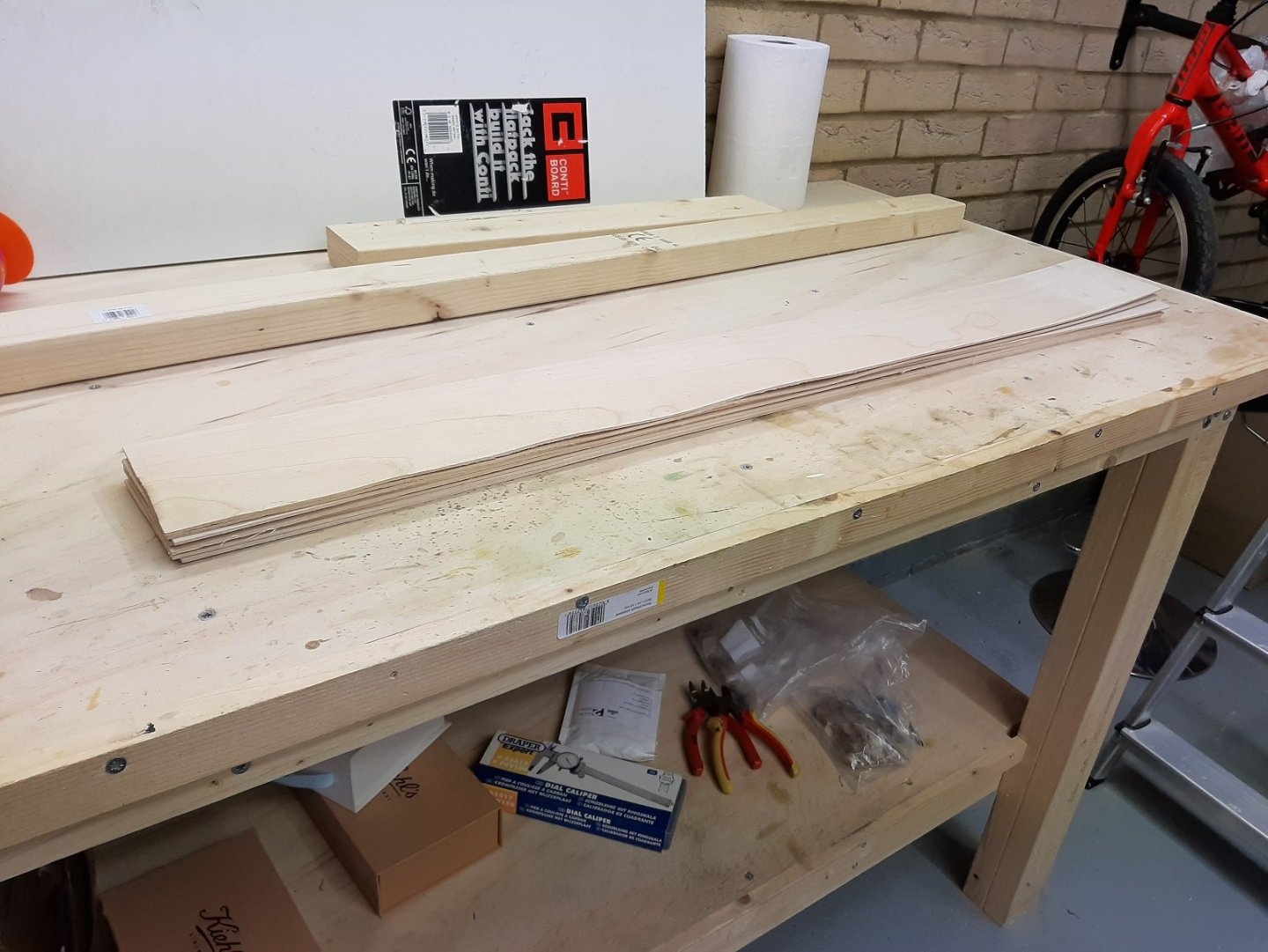
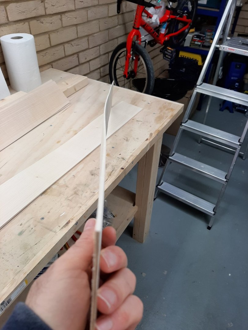
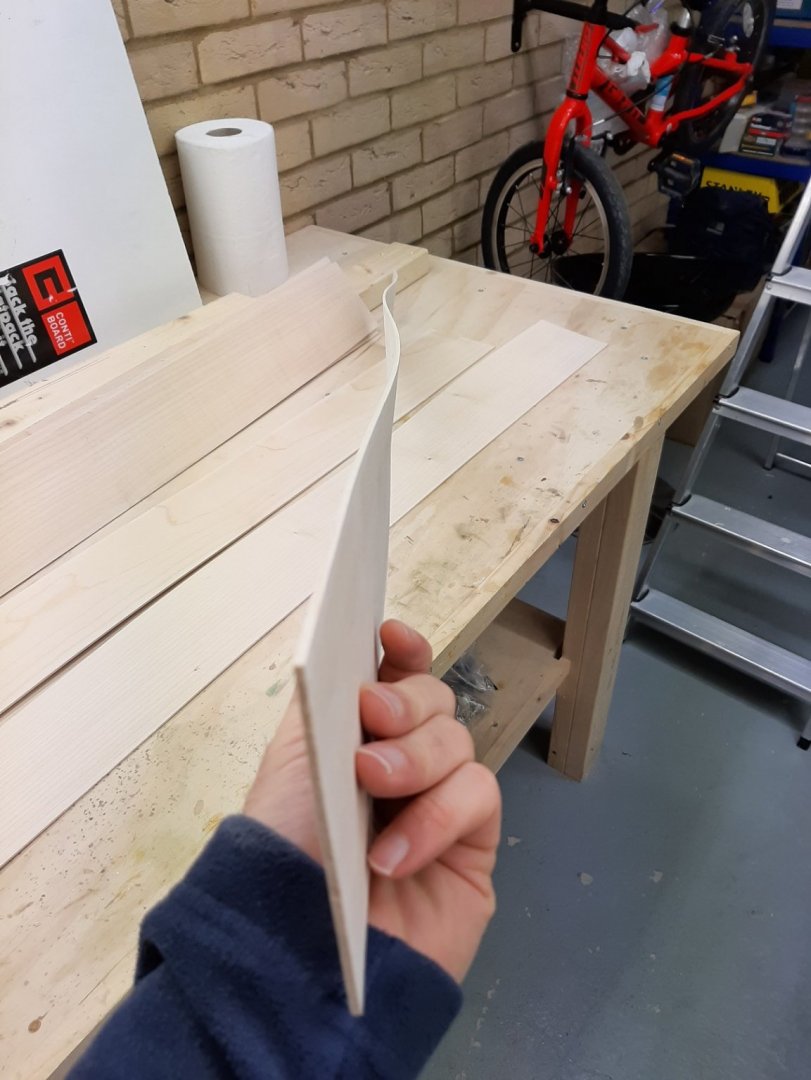
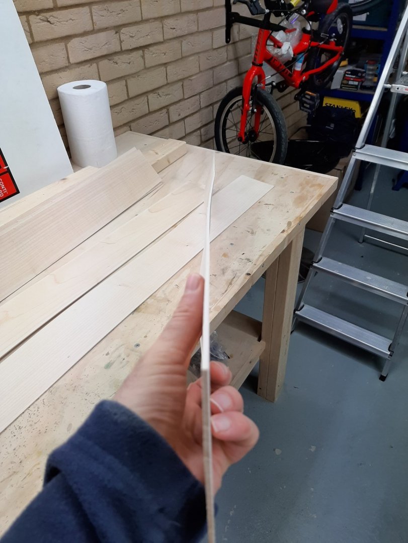
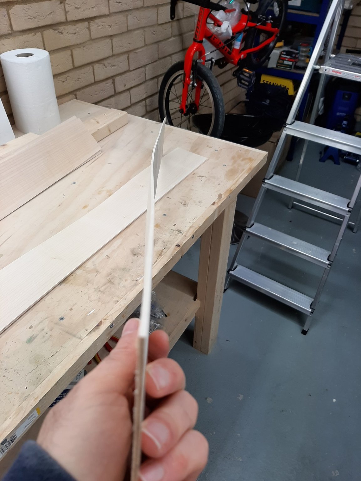
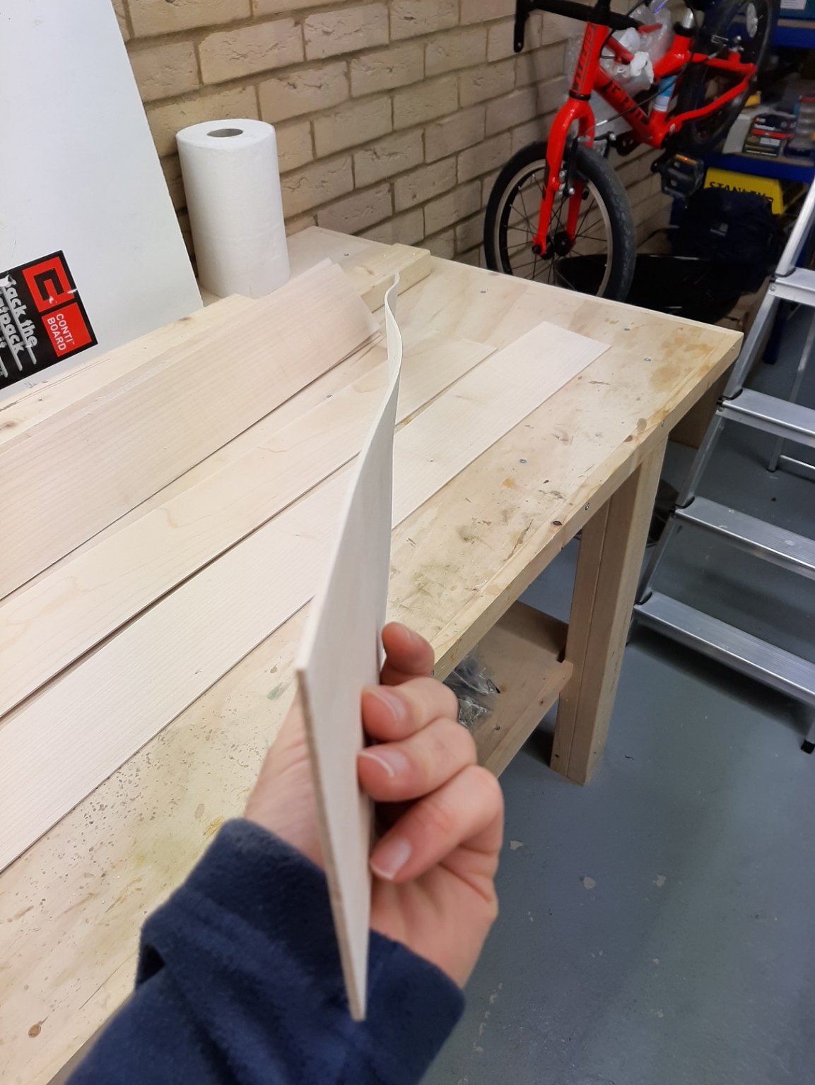
Dear all I threw the sheets in the bathtub and soak them in very hot water. Then I took them to the garage, flat on the work bench with a sheet of particle board on top and whatever heavy items I had laying around pressing down. I repeated this cycle twice. Much improved situation, some sheets better than others. Some are dead flat, others have one edge straight and the other a bit wavy, others still a bit wavy. They are all however usable now.
-
Newbie paint questions...
vaddoc replied to CPDDET's topic in Painting, finishing and weathering products and techniques
I would suggest to use only paint products specific for modelling. Much better pigments and quality. Yes, with practice you can brush paint with very good results. Spray paints are expensive and messy I have found. With acrylics you need a top coat, mat in your case. -
Many thanks Dan! Actually I do have May's book, it contains some good info. I will look up the other book. I ll dare say that I am not too stressed with the planking, I think it will be ok. I just do not know how these boats were put together back then. At 1:10 scale mistakes are much more visible. At this scale a model very close to the real thing can be produced. Anyway, we ll cross this bridge when we get to it!
-
Now, this is a good idea, much appreciated Bedford and Michael! I wonder if ordinary cement glue could be used, I think it dries rubbery. Many thanks to all!
-
I remember spending 4 months drafting by hand, making all the frames and then binning everything and starting again. It's not often in life you get a second chance but you do in model building! Have fun and do not worry, all will fall into place in the end.
-
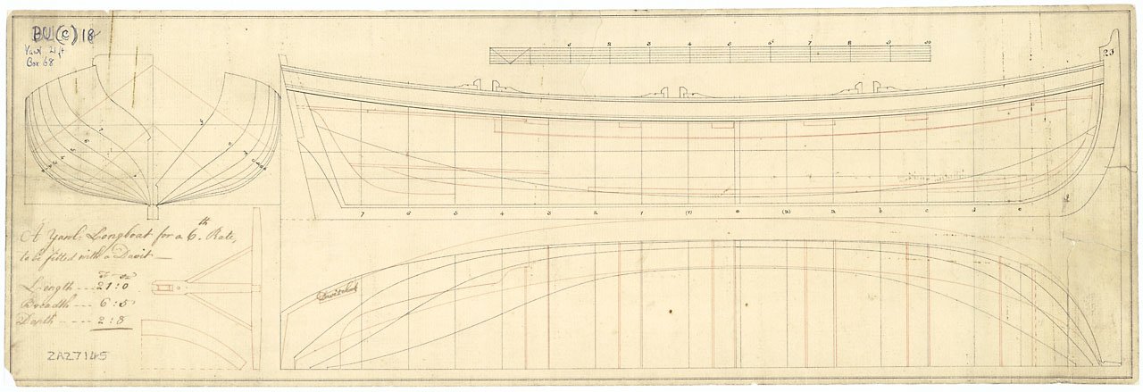
Now, I did not really intend to get involved in a project like this. My current boat (Deben 5 tonner) still needs a lot of work and has been going on for close to 4 years. However, this week I somehow found myself with a lot of free time to sit in front of a computer but not being able to work in the garage. I stumbled across the prints that the National Maritime Museum sells and there were some of boats carried by ships of the line that looked nice and detailed. I have always wanted to draft from printed lines and I ve been missing messing about with planks so I started playing with CAD. I just used the images the museum has on the on line shop. I progressed rather well, kind of 20% through the first lofting, so I thought I ll start a log initially with the CAD lofting and then with the boat it self, provided of course I ll get a reasonable result. Without a deck and rigging and with just a few planks it should not take more than 2 years to complete... I would like to try and do a nice lapstrake, not sure if it is historically accurate. Also, I cannot find easily much info on how these boats were actually built in terms of stringers, thwarts etch so I ll use some more modern arrangements and hope for the best, unless in the meantime I get by some more info. I admit I have not searched through MSW yet. I would like to try for a quality model, choosing appropriate wood, lining up holes, being careful with fit and finish etc. We ll see.. Enough talking, lets get down to business. This is the set of plans I used. The print costs £25 and can be ordered on line but as I said I just used the picture uploaded on the webisite. I think we are ok with copyright issues. More info on https://collections.rmg.co.uk/collections/objects/86936.html The plans show that this boat has a Davit but I will ignore this, at least for now as I do not really understand how it works. It seems like an interesting twist though. These plans are really very detailed. They include the keel, three WL, two diagonals, the sheer, all but the middle frames (this seems to be common practice) and also some of the interior arrangement. They proved later quite accurate and it is amazing that people can produce this with a ruler and a pencil. Especially the accuracy of the diagonals is impressive. Tracing the lines showed that there was slight distortion of the paper so adjustments had to be made. Getting all pieces in the correct position produced a half hull In the next photo, the sheer was created from the two views (red lines) provided in the plan. It fits the frames reasonably close. After I took this screenshot I had to re position all fore frames to account for the missing middle frame. This sorted things out. Later on I also found a small mistake and correcting it raised all the frames a bit. These is the top view of the waterlines. A bit of effort was needed to get them somewhat fair And on to the hull...not too bad. The diagonals (blue) are also added The sheer seems reasonably fair. This is the only line that really needs to be fair as it will not change and will be a reference line. All other lines except maybe the diagonals will change during the lofting cycles. The waterlines are also faired but these will get adjusted many times The hull with just the lines. Note that the transom in the plans is given in its vertical projection. It first needs to be projected in the angled plane it would normally be prior to adding to the hull This concluded the first part which is to just get all lines drawn. Now, the first lofting cycle begins. I created two more WL to help me maintain the shape of the frames in the upper strakes (green colour) I decided that the diagonals are the more accurate lines and I will follow these, using the WLs to maintain the shape of the frames. This is how I arranged the new shape and how much off the frame was. Not too much really. The small horizontal lines were added to maintain the distance from the old line, so keeping the same shape as close as possible. Later on, the WLs will be created anew and faired and the cycle will begin again. In the next two photos, you can see that the frames on the left side that have been faired follow the lines much closer than the rest Now we can try and create a bit of surface with the frames we have adjusted and see how it looks and how smooth it is. The points and lines from adjusting the 5th frame can be seen in the background. This is not bad at all considering that the waterlines have not been faired back at all. Of course the difficult areas will be first the two segment at the bow and possibly the transom. To my experience the transom always creates problems! It looks promising though. I am not sure when I ll have time to do any more work on this but it has been fun. If I ever manage to build this it will be a big baby at 640 mm LOA, some planks will be close to 80 cm long! Off to a very busy weekend, I will be doubling the lighting in my garage, it should be as bright as a supenova afterwards. Regards Vaddoc
cropped.thumb.png.64da0c5486f4900ffd7b9dd417d293d4.png)
cropped.thumb.png.21f1d4a3a7b7261b0230e00e4ee0d907.png)
cropped.thumb.png.a8425a74bc480511f7716eecb3c446c9.png)
cropped.thumb.png.f588130825940cec6cfeb5905c84e774.png)
cropped.thumb.png.3aa8727d55571d503c61ee5d3f92e916.png)
cropped.thumb.png.3891bad48a5de6dde675c9eb7bb2e066.png)
.thumb.png.96fcc1de9fad79d4fe1e1c1ea7fc3436.png)
.thumb.png.e0093a2684c49af39dcfd5f05abe2ab3.png)
.thumb.png.85e73955249e7eeb71251718fd8aa2df.png)
.thumb.png.9d443c094c267acfedb70cef880bf88c.png)
.thumb.png.62f659e540c08174a003759f7b2ddf6f.png)
.thumb.png.88bc753c0e2f6aba3245942b711b5c30.png)
.thumb.png.d2c873e98758556488fd74334ccd7dc2.png)
.thumb.png.7d5d832dbaa5fd2b7e4296680a7588f6.png)
.thumb.png.8d256c385d136b48dde0eeca245d3050.png)
.thumb.png.5ab2c4518720341024e6eb690163b821.png)
- 232 replies
-
- 18
-
-

.png.6feb3ce038b77a09388405da6449f266.png)
.png.b8622d3e37d5b211af172f60560e67c6.png)
.png.ac7e66a0dd65e0502611f1a2a87904b8.png)
.png.b2445a5876f562d64985ccad1cbad6cb.png)
.png.c4f63ba65a7d1b02bbbb63a997205752.png)
.png.9f5373e64c5d45868ad73afca594709d.png)
.png.e39ebd458fdfd0eed40d436c5b88284b.png)
.png.54e74cd5a4bd562af06c40bca544ab59.png)
.png.4848cbd53052919b909eaba117f97e44.png)
.png.09c6aa929803eafc9f41bde5f4a68b97.png)
.png.b1326ee32e3d90c79ee854433c466da4.png)
.png.a3acb13ac5412aedbc3aec7c606befae.png)
.png.38ef38953ac61c19aad90ff75f68cb8b.png)
.png.0eaeffa418b96d44a701ae6d9893cace.png)
.png.48b0c253035c4c762cfef921cdca4d43.png)
.png.e8fbbe4d4e974d74f477838e93c5b214.png)
.png.2c7a03fdf79f0be4320feb7573069a87.png)
.png.f6f91a79a1a65c7748ae8d91904b6b51.png)
.png.2bbd9b2235e0270b657ca9a225ce62ba.png)
.png.a25924a9b907a659af5ef71e47f4ba9d.png)
.png.d2386d4ad55e317f741bea87a41d7c87.png)


cropped.png.c8c93436d7610c3581cdbc09ea2ce9a1.png)
cropped.png.286b2028d1ca0338407d4c72ed498302.png)
cropped.png.29efca76a26ca49cda3081d3913546ce.png)
cropped.png.9d03b140631b911b5592c085f23d0882.png)
cropped.png.2429495eb2041286ca7e3ec7b3d6ff54.png)
cropped.png.de239418595fea8a7b28e0ca036b8a70.png)
.png.22678a93620cdcd26f6295ff1df95f2b.png)
.png.66c47f3989a8c254bdb704f74bdd5e86.png)
.png.7f90347b3e8d8303c19635dd79cbb817.png)
.png.2c9727e8d613bb213ccd41a6f383fb90.png)
.png.003075eee1a91a420c6bed53b164b5e6.png)
.png.04d0f8455b35481cc3a4140bec2ff510.png)
.png.f4d7e016567ae28d9336b7ccf6a7b8af.png)
.png.a82fcfa105398891a7592ea240684306.png)
.png.1ae74c7abf234c937b2fa115309d4ccf.png)
.png.5a1bf2b8a15d6caaaf5aefd8d64d5cc6.png)