catopower
-
Posts
1,900 -
Joined
-
Last visited
Content Type
Profiles
Forums
Gallery
Events
Everything posted by catopower
-
 Unrelated, but did Model Shipways really call the Bluenose a New York Pilot Boat of 1868 on the box like that?
 -
A.Jorden, I've bought several sizes of copper foil tape from glasscrafters here: http://www.glasscrafters.biz/CTGY/foil Get the exact size you need for your scale, uncoated. Clare
-
Is Warner Woods West still in business ??
catopower replied to Teakfreak's topic in Masting, rigging and sails
Hi Ed, Lloyd retired from the line and block business... I want to say it was early last year (?). I really liked his blocks and still have a small supply of them, which should finish up some models projects I have. Sad to see his products go. But, as Tom points out, you will not be disappointed with Chuck's stuff. Beautiful quality stuff at reasonable pricing. Easy to purchase. Clare -
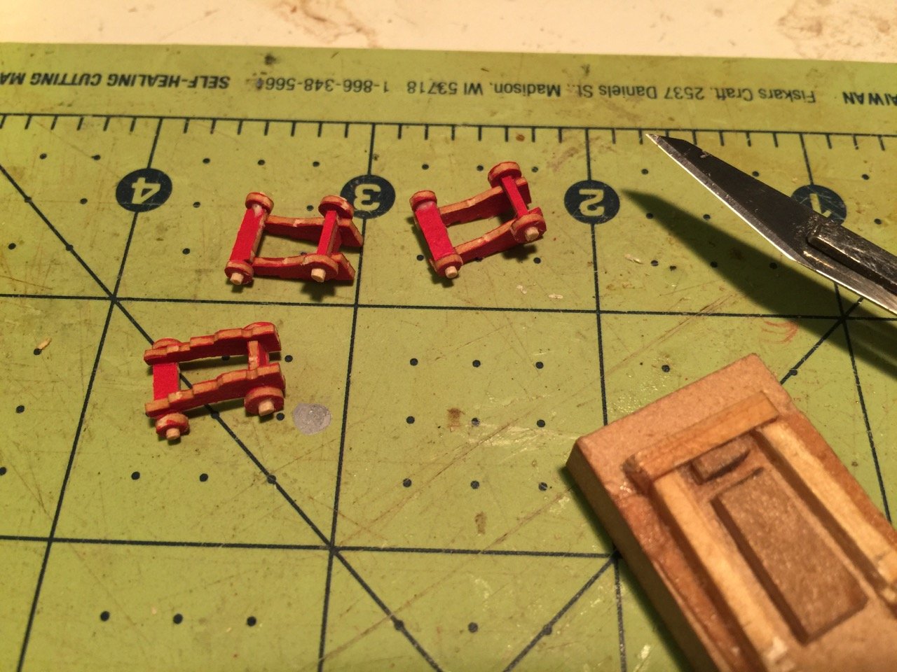
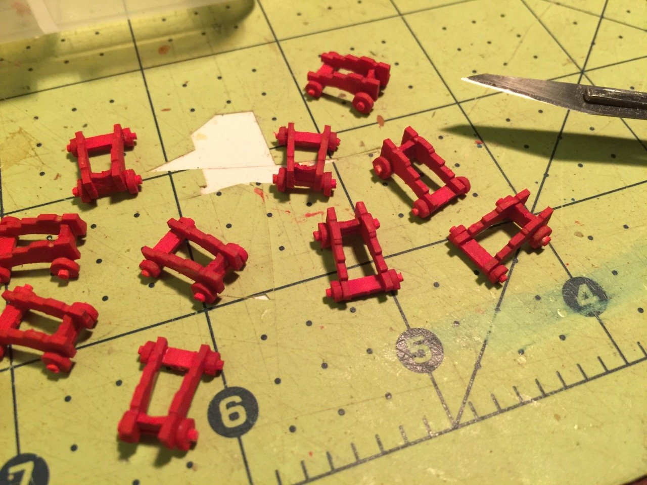
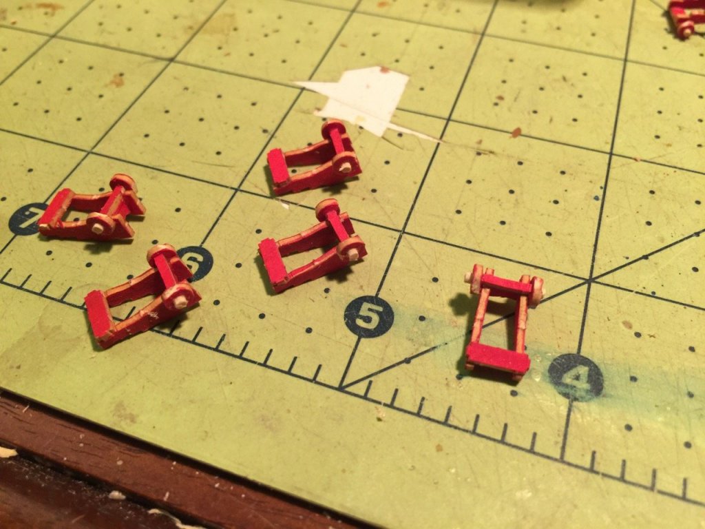
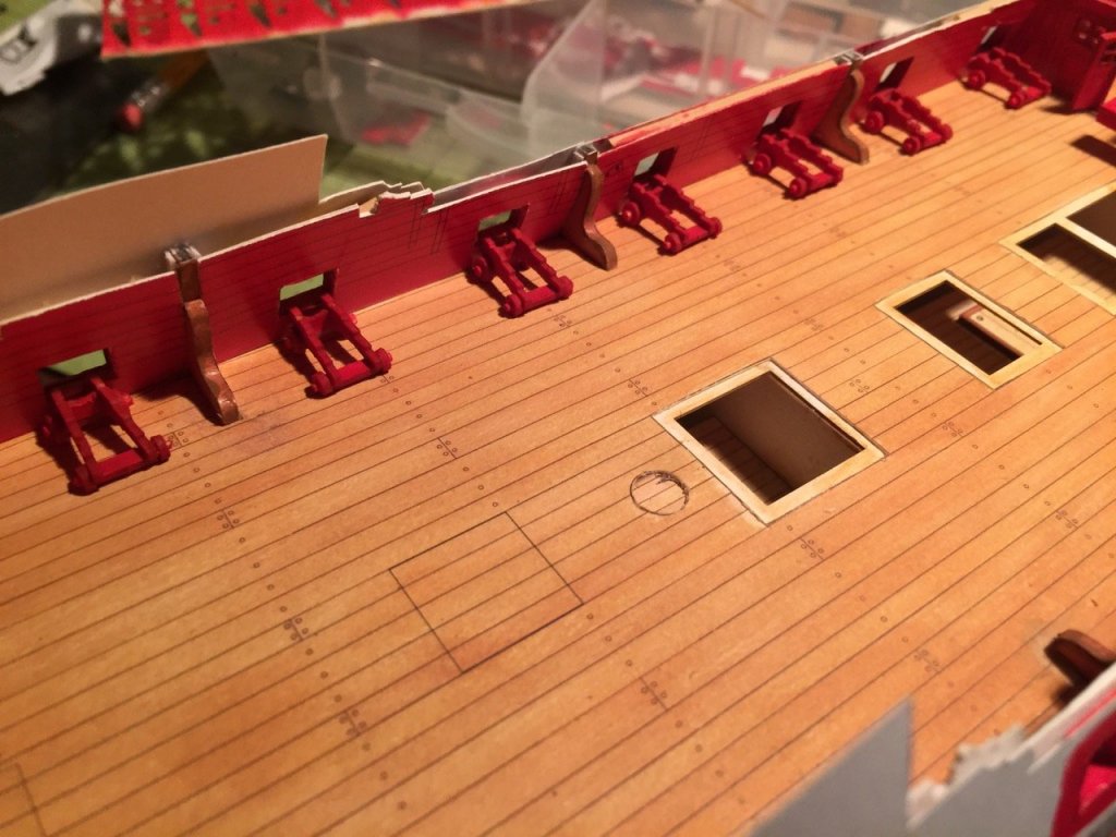
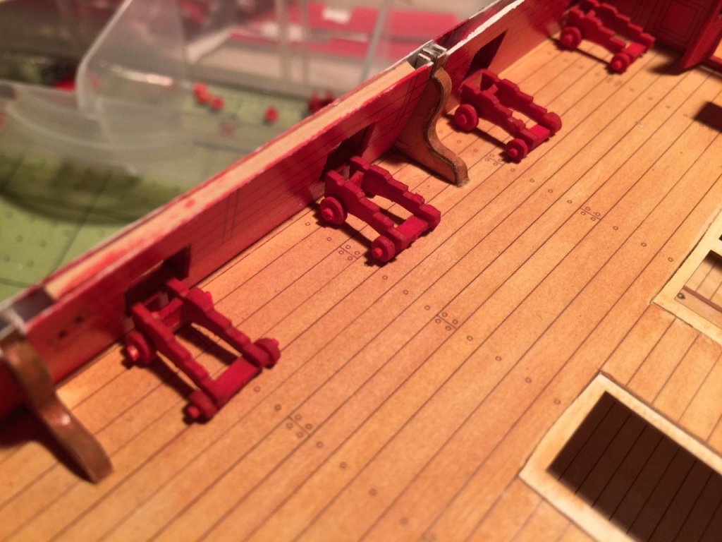
And speaking of the GPM detail sets, here are some photos of the cannon carriages built from the GPM detail set. Construction is mostly complete on the first half of the gun deck carriages. I still have the ironwork to do, a little cleanup, and I have to figure out if I can add the quoin and quoin bed. But, I'll make the barrels before I to that, so I can determine if I ca fit them in and have the barrel elevations look good. The quoins in the detail set are extremely tiny and narrow, so they're hard to see and work with. I didn't use them on the Alert, and I don't think it mattered at this scale. On the Alert, I also only rigged the breech ropes and not the tackle blocks as they would have looked way out of scale, so I preferred to omit them. One issue I ran into, which I didn't deal with on the Alert, is that the detail set has a hole in the gun trucks for an axle, but don't provide any detail for the axle itself. I just used the carriages "as is" on the Alert, which looked fine. For HMS Mercury, I thought I'd deal with that detail by shaving down a basswood dowel to 3/64" diameter for the forward gun trucks. The rear trucks have a smaller diameter hole, so I took the leftover dowel and shaved it down to fit. I just glued everything up using Elmers wood glue. After it all dried, I then took the completed carriages, and applied thin CA to stiffen it all up. Without the CA, it's flexible and still a little delicate. The CA wicks into the card stock very well. I finished painting the carriages with the Renesans Colours acrylic paint. Color number 08 is a perfect match for the printed parts. I think I mentioned before that I really like these paints and I finally found a source in Poland for them, thanks to the folks at Papermodelers.com. I've since heard from a fellow ship modeler, who read my post about them and also managed to buy successfully from the same shop at https://www.swiatmodeli.eu/pl/c/Renesans/58. Below, you can see the visual test I did, just to see how all the carriages will look in place on the model. Still have another dozen carriages to do for the gun deck. Then, I need to do the ironwork. After that, I will have to tackle the making of the barrels – something I avoided on the Alert by using 3rd party brass barrels.


-
I will say that I kind of wish that I had started Shipyard's HMS Wolf first. I think it's fully open gun deck would make construction simpler at this point. Only issue would be that GPM doesn't make a detail set for that kit. But, as I did with the Alert, I think it would be simple enough to adapt parts from the HMS Mercury detail set, such as cannon carriages, blocks, gratings, etc. Still, enjoying the HMS Mercury build.
-
Hi jct, The laser-cut parts do help a lot. I don't have to cut or laminate the parts. The only issue is that the card stock sheet isn't as sturdy as laminated thin paper. So, I'm finding that I have to be more careful with them. Tim, It's been fun and challenging, but it's hard to say if it's really quicker or slower than an equivalent wooden kit. If I were working in wood, I'd spend more time thinking about how I want to approach each step. Also, since I've been a wooden ship modeler for over 20 years, I'm more concerned with how to get the details right. The paper model kit pretty much does what it wants and I probably don't spend the same kind of time getting a detail just right when I'm working with paper – I'm just happy if things fit together well. Technically, I think building a paper ship model kit is easier than building a wooden ship model kit, at least this type of build. It's a simpler skill set: laminate, cut, fold, glue, etc. But, there is a LOT of it to do, and you have to be okay with that. Masting and rigging should be about the same. If you're scratch building or modifying, then that's an entirely different story, which I can't really comment on. At least not yet. I'm looking forward to seeing you start a build log. Then, maybe you can show me how to build this thing correctly! But, this is fun. I'm really enjoying it (the laser-cut GPM detail set helps). It's mentally much easier than working with wood, takes up much less room, uses few tools, and is less messy than working with wood.
-
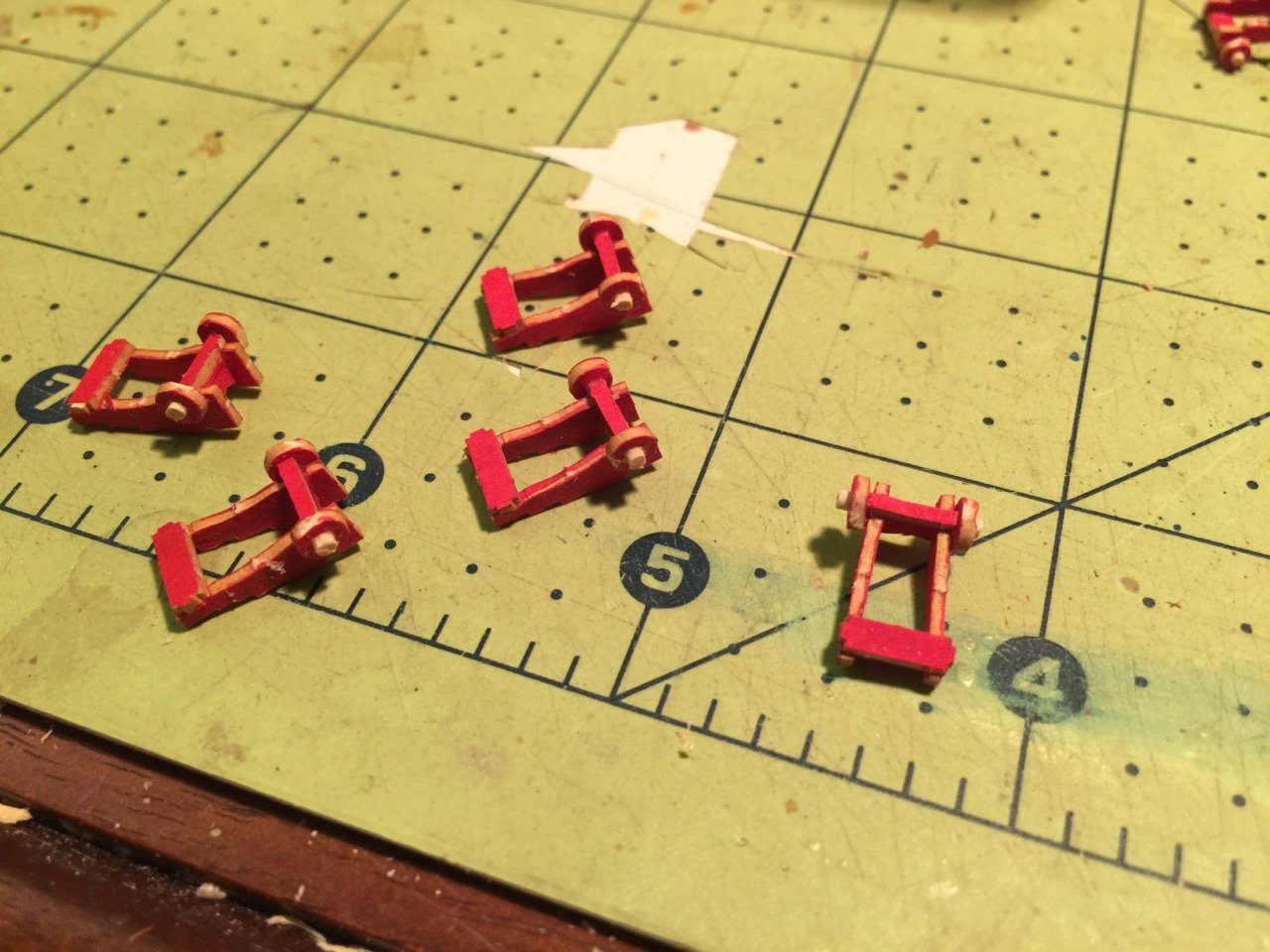
HMS Mercury's Cannons Before I can put too much of the interior detail into place, I really need to add the cannon carriages and probably the gun tackle too. The main reason is that if I am going to add any amount of gun tackle, I need some room to add ringbolts and blocks and such in the tight confines of the model's interior. This will be more difficult if I try to do this after adding other interior furnishings. Now, if I built this as a real dockyard scene with launch flags flying, as I've been considering, the cannons wouldn't be on the model at all, as this was something done after launching. Of course, I could take some artistic license and create the launch scene, even if I do add cannons. I'm still a little torn about the whole idea of the dockyard scene, because it feels a little like cheating since I'd be avoiding all the masting and rigging. But, I've seen some beautiful models built in this style. And who's to say that I won't build a fully rigged paper model next time? Yes, of course I'm rationalizing. In any case, I think I've decided that I'll add the cannons regardless of the final model type. I can go ahead and get started on the carriages first. I will then give some thought to the barrels and the gun tackle. I think it's common to build a ship model where the cannons have no tackle or just the breech ropes rigged. But, a serious ship modeler would most certainly fully rig the cannons, and I expect I will do just that. And the barrels? I used brass cannon barrels on my HMS Alert model, which look absolutely great, but I may just put some effort into making them out of paper this time. Anyway, I don't know of good sources of small enough pre-made carronade barrels, of which I'll need several for the quarter deck. But, first things first. Time to make carriages. Building the Carriages The task of cutting all the parts to make good looking gun carriages can be quite intimidating, particularly the trucks or wheels. Luckily, this step is simplified by the fact that the GPM HMS Mercury Details set I bought includes all the gun carriage parts all neatly laser cut. I've generally been pre-painting the laser-cut parts before removing them from the sheets. The Shipyard printed parts are a natural wood brown color, but if you look at a lot of dockyard models the gun carriages are most commonly painted red, and this is the way I've decided to go with this model. It's easy enough to choose the desired color since the laser-cut parts need to be painted anyway. I painted the carriages using Renesans brand acrylics from Poland, specifically the Renesans Colour 08, Cynober (Cinnabar). I've written about my hunt for this line of paints in another post. As an alternative, I had initially tried to use Blick Matt Acrylics, Deep Red, but it was just a tad darker than I wanted. My desire was to match the color of the printed bulwarks as closely as possible, and the Renesans paint is a better match. Since I painted the parts before assembly, once the carriages are completed, I'll have to go over them one more time to color the edges. Also, I'm going to try a little gloss medium in the final paint coat to make them less dead flat.
- 82 replies
-
- 12
-

-
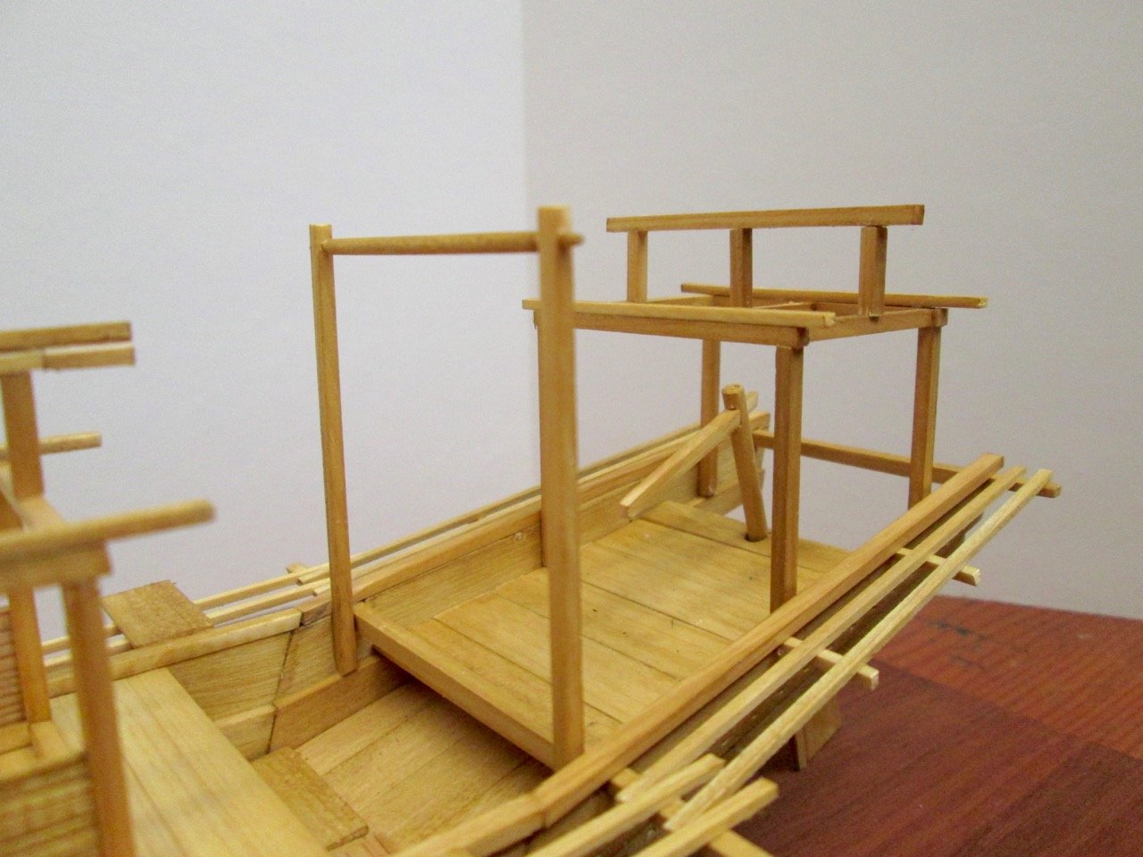
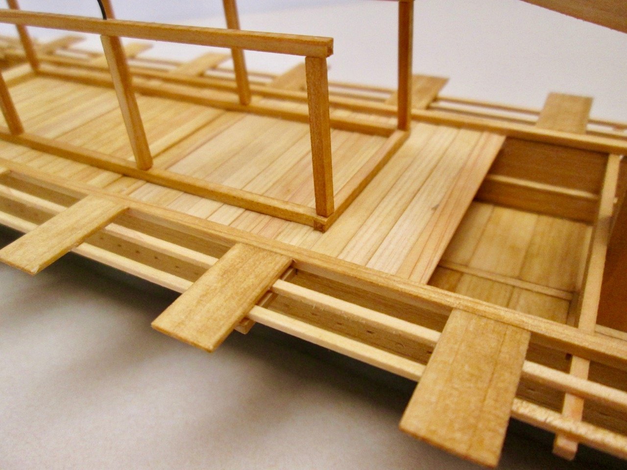
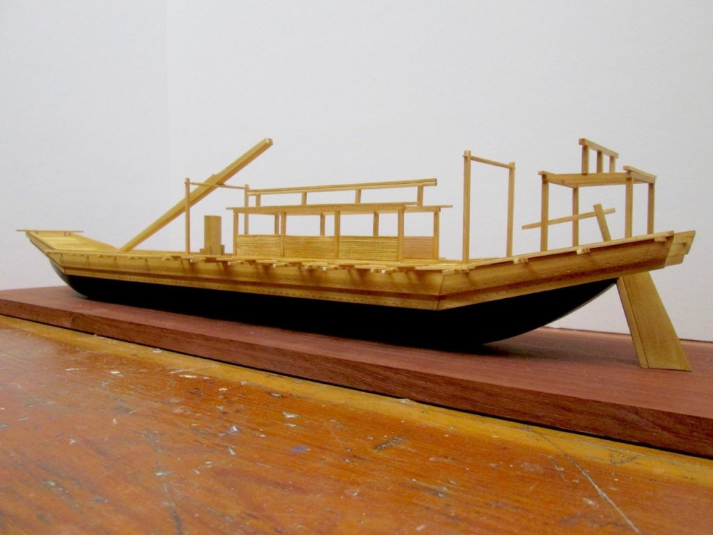
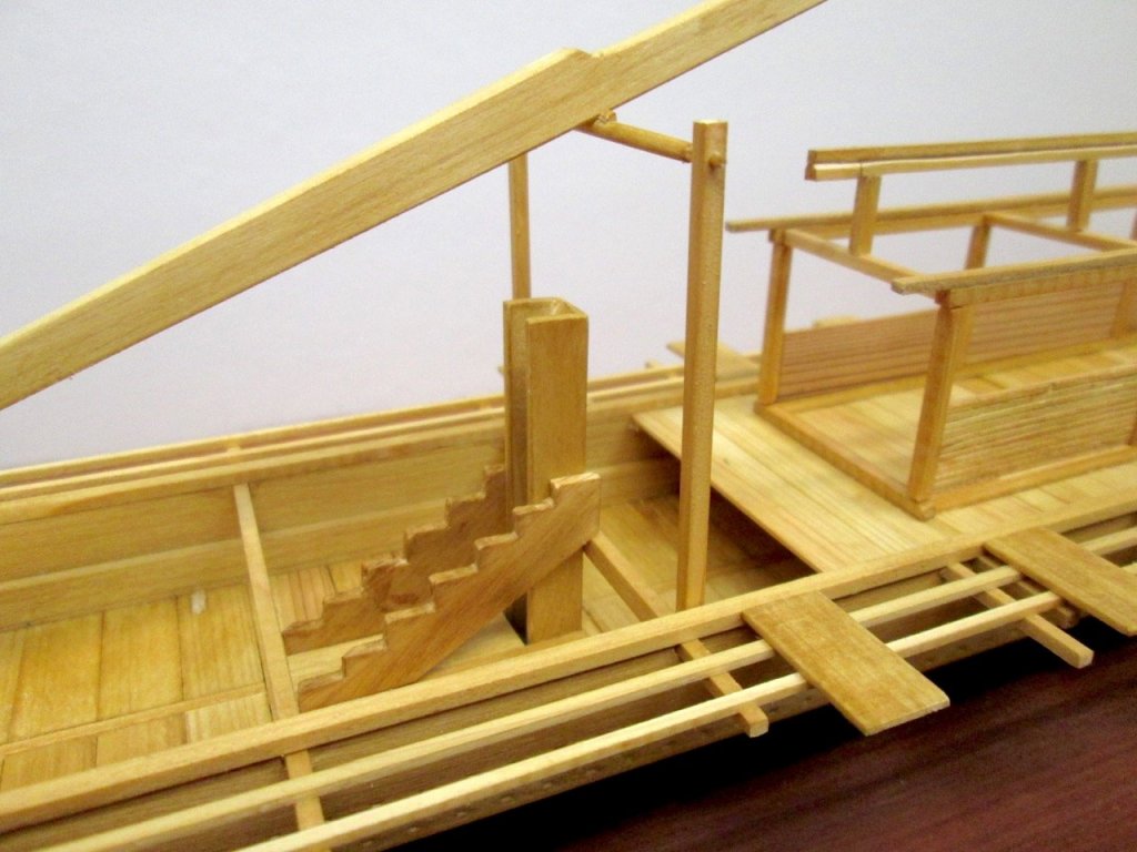
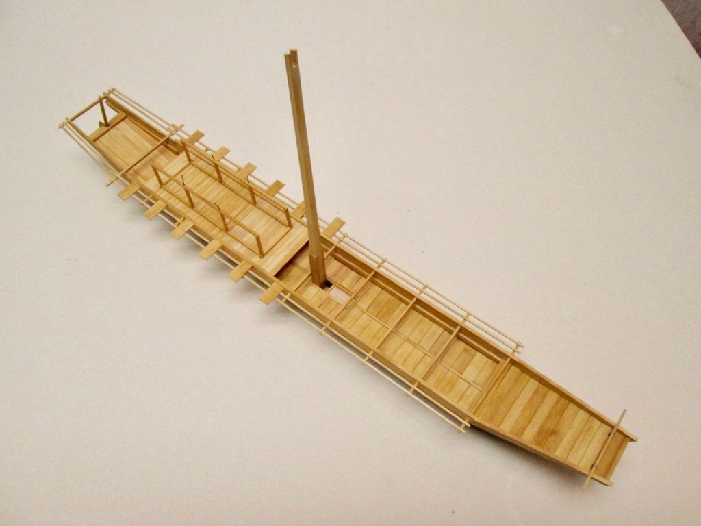
It's been a while since I've update my build log. After a long stretch of overly quiet time with my regular job, things got really busy for a couple weeks. That was on top of a series of projects and tasks I needed to get done this week. Today was pretty much my first full day of rest after spending yesterday playing catch-up on all the things around the house that I've had to put off. Getting back to the Umibune here, but, unfortunately, I kind of jumped ahead without taking many intermediate step photos. As I mentioned before, this has build a project where I've been really trying to figure out the details of the subject as I'm building it. This has led to one issue of building the deck houses, or yakata, on the model as I go. With these fragile structures, it would have been a lot easier if I could have built them off the model. But, it is what it is. As you can see, I started the framework for the aft structure and added a peak roof beam. I also added one to the main structure. You'll note that the roof of the aft structure runs perpendicular to the centerline of the vessel. Also, the frame construction is a little odd, because the aft section of the vessel narrow toward the stern. It's not all that clear how this affects the roof, as the reference drawing doesn't show a top-down view of the roofs, and the roof's shape is not discernible from the scroll painting. Since the walls don't actually cant inwards very much, I figure that it's simplest to build rectangular, as if all the joints were at 90 degree angles. In addition to the deck house structures, there are a pair of cross-beams mounted up high on posts. I don't know exactly what these structures are for. But, often, the mast is shown leaning on them. Also, the height of the cross-beams is above the top of the roofs, so it might be possibly to lay something across the top, again, perhaps the mast. These were used to tie pole-mounted lanterns to (see the scroll painting) and might have also been used to tie banners. I set the mast in a lowered position, leaning on the forward crossbar, but I don't know if that's how I'll display it. Still have to think about the sail. You can see I also added the wall panels on the main yakata. I wasn't sure how these would have actually appeared. To me, it looked like these might have been something like rattan. Not wanting to weave these, I ended up taking very thin dowels and glueing them side-by-side to a wooden backing. When the glue was dry, I then pressed across the dowels at a 90 degree angle with a dull blade. This crushed them a little, making not only the cut, but leaving the suface slightly rounded at each cut. From a distance, I think they look okay. I will probably do the same thing for the upper panels, though they will be mounted in an open position, "hinged" open, and secured by some kind of hooks to the underside of the roof. At least that's the plan.


-
Those cannons are looking great Nils. Sorry I'm late with the wishes, but a belated Happy Geburtstag to you! (Sorry, I couldn't remember how to write the whole phrase in German)
- 692 replies
-
- 5
-
-
- eagle of algier
- chebec
- (and 2 more)
-
jct, it looks like you've solved the color match issue. The hull looks great. On my HMS Alert, which used printed paper (as opposed to the boxed, laser-cut kits which require you to paint the whole thing), I ended up painting almost every single surface in some way. Even my deck has a thin wash of paint. I think it actually makes the paper model of the wooden ship look more natural. Looks great. I'm going to start experimenting with the acrylic mediums myself. Nicely done!
-
Dr. Per, I believe that this is an earlier Swedish-Nowegian Union flag which was in use at the time of Mariefred's construction.
-
Hello Nils, Just catching up with your work now. Wonderful work and progress on a most interesting subject. I'll definitely be following along!
- 692 replies
-
- 5
-
-
- eagle of algier
- chebec
- (and 2 more)
-
Hi jct, The paint I use is the stuff that Shipyard used to sell. It's still used in their boxed kits, though they put it into their own jars. The brand is an artist's acrylic called Renesans, specifically the line called Renesans Colours, but it's a Polish brand and it's hard to get here. I really love the stuff because it's a dead flat color that has some transparency. You thin in way down and it still adheres well to the slick paper. I found a source, but it's in Poland. It's not a problem, except that they only take bank transfers as payment. In the US, banks charge $25 a pop for the privilege. The closest alternative that I've found are the Blick Matte Acrylics. They're again artist's acrylics, but they go on dead flat. Best thing, for artist's acrylics, they're pretty cheap at $1.99 for a 2 oz. bottle. You can get them direct from Blick: https://www.dickblick.com/products/blick-matte-acrylics/. It's actually very good and I may switch to it since it's easily available. Regarding planking material, I personally found that high-end inkjet printer paper works really well. It has a very smooth surface that takes paint really well. I laminate a few sheets together using 3M spray adhesive and it should give you planks, or parts, that are strong, but flexible, easy to cut cleanly, much better than cardboard. In fact, I don't like using cardboard, I much prefer laminating these sheets together. You get much cleaner edges that won't break down the way cardboard can.
-
Thank you for the nice comments Druxey, Carl. It feels a bit simple at times, given the purely straight lines of so much of this build!
-
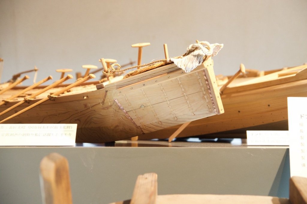
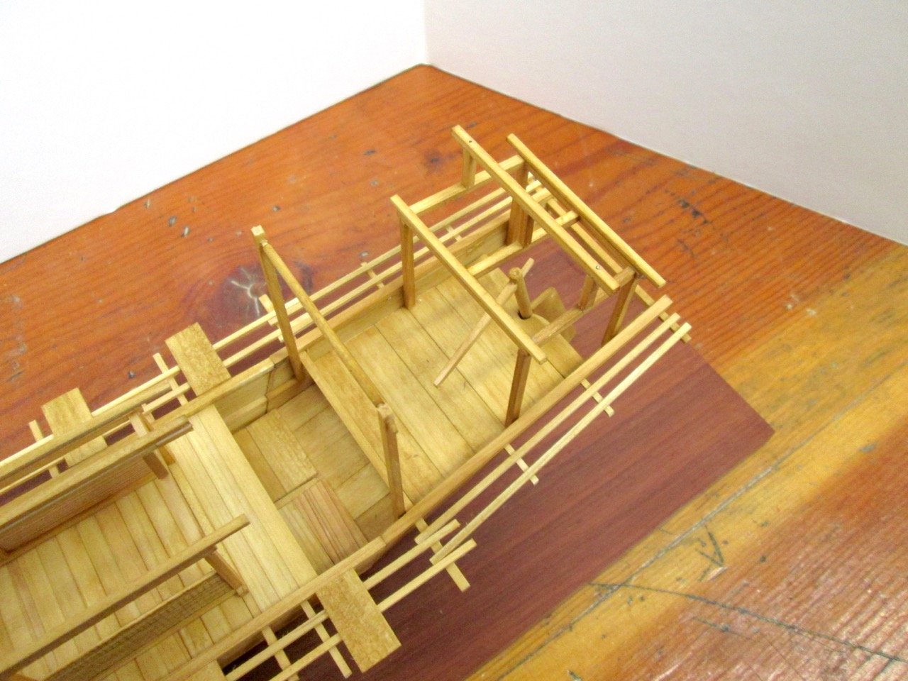
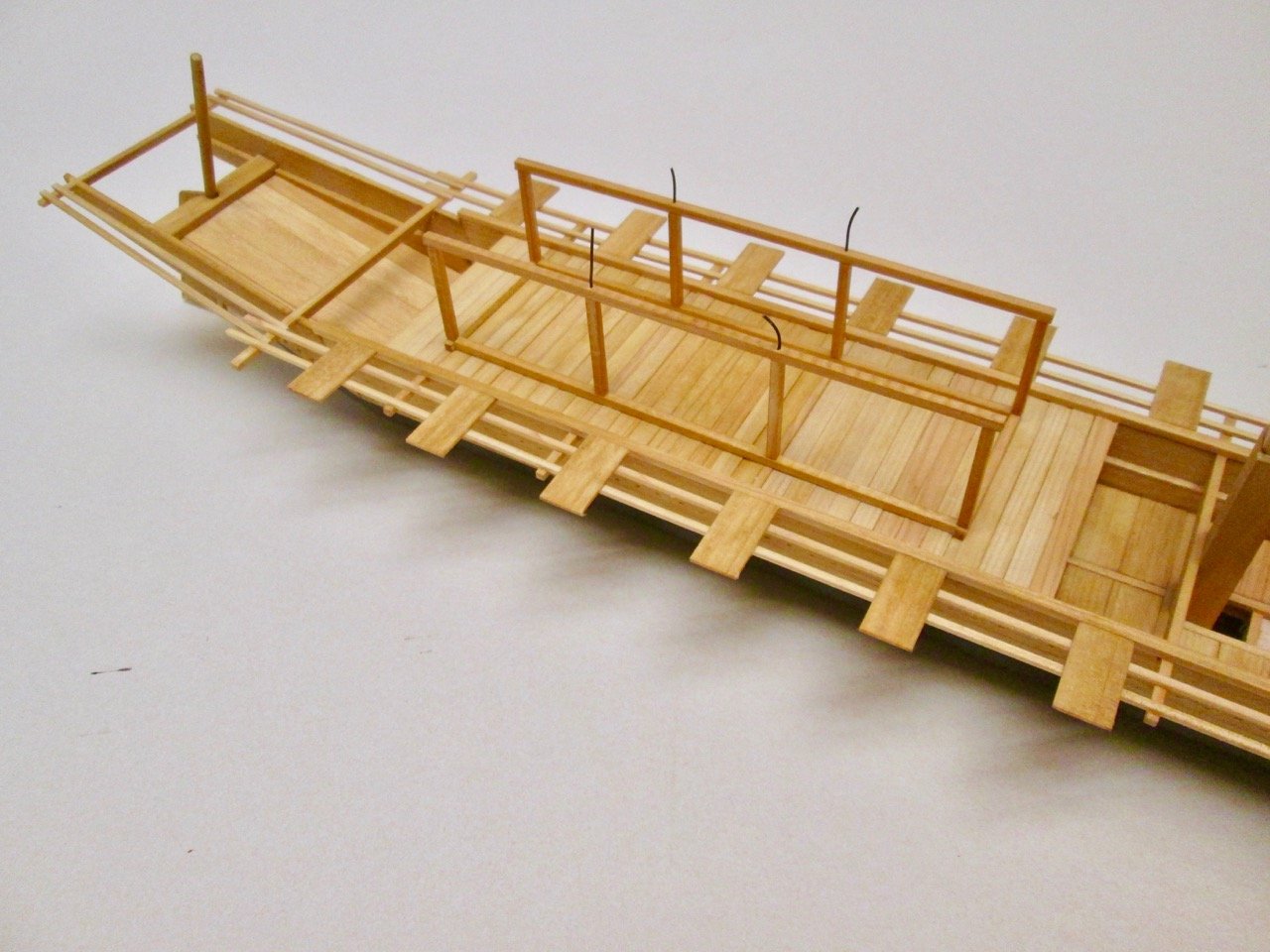
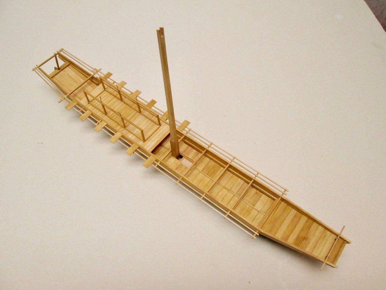
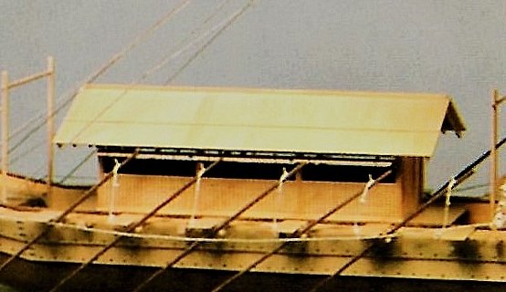
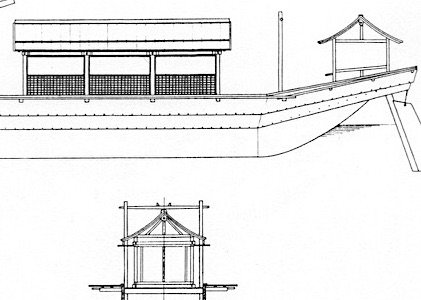
Time to get back to posting about the Kamakura period large sea boat... First off, when I initially described the Japanese name Kamakura jidai no dai umibune, I may have been incorrect. I'm thinking now that it should actually be Kamakura jidai no taikaisen. Something to do with the way the Chinese characters are read, which I'm not so up on. For now, without the character for large, 大, (the full name written in Japanese is 鎌倉時代の大海船), it is still correctly read as an umibune or sea boat, so I'll do that. The next step after getting the raised planking into place was to start adding the yataka or the deckhouse. Now, this part of the build gets away from most boat building, as I think this is just a basic Japanese building structure that's been attached to a boat. Having built Woody Joe's Yakatabune kit may have helped a little. The overall structure is similar, though that boat was fashioned after those from the Edo period, which is 300+ years after this umibune. I had a hard time finding any information that helped, though I did buy the book The Genius of Japanese Carpentry, by S. Azby Brown, which did help me out a little bit. Mostly, it served to show me how little I know. Still, there were a couple pictures that showed features something similar to the umibune's deck house. Also, I built Woody Joe's Shinmei-zukuri shrine kit, which I hope would help a little in the old style building construction. But, the umibune's deck house structure is very simple and lightweight. It is basically a frame work with a gabled roof which, on some paintings and models, pitches upward toward the peak. The only fixed walls are the lower half of the sides of the deck house. The ends appear to have been open, covered by no more than some kind of roll down screen, which I suspect must have been fastened down to the floor to keep it from flapping about in the wind. The upper half of the side walls was open, with a cover that is hinged at the top, and it usually depicted as hooked in an open position. From the model that used to be in the Tokyo Museum of Maritime Science. Using the above drawing, I began to lay out it out. Being fairly As you can see in the photo above, I reinforced some of the joints with wire, which has yet to be trimmed off. Also added are the remaining aft outer rails or segai, and the rowing platforms called rodai. Below is a birds-eye view with the mast temporarily stepped. Still haven't decided if I'll have it in sailing configuration or not. And then a close-up of the beginnings of the deck house structure. Just winging it here...


-
Hi jct, What I was thinking I might do is to score the lines of the planking, which should make the piece conform a little better. It would need a light wash of paint to kill the white of the paper that would show through afterwards. I actually use paint washes pretty heavily on my HMS Alert, keeping them really thin. That worked for the most part, though I fully painted the lower hull. When you turn your model over, I expect the issues you were having with the lower hull won't be so prominent. Also, something I learned with the Alert was that as soon as you put paint down on the model, it looks better, overall, if everything has a thin wash of paint on it. Evens out the look.
-
Hi jct, I understand the problem you faced there. I have been thinking about a similar issue I'll face when I get to the hull planking of my 1/96-scale HMS Mercury, which also has planking added in strips 3 or 4 planks wide. I didn't have that problem with the HMS Alert, because it has the clinker planks that go on afterwards and cover that part up. I'll probably be painting too!
-
Heinrich, I'm happy to see your build of this Shipyard paper model. I built the 1/96-scale HMS Alert kit, which has very similar construction, including the clinker planking. I've often thought about building Shipyard Le Coureur kit. After all, they did engage in battle. I will enjoy following your build here.
- 21 replies
-
- 1
-
-
- shipyard
- le coureur
- (and 1 more)
-
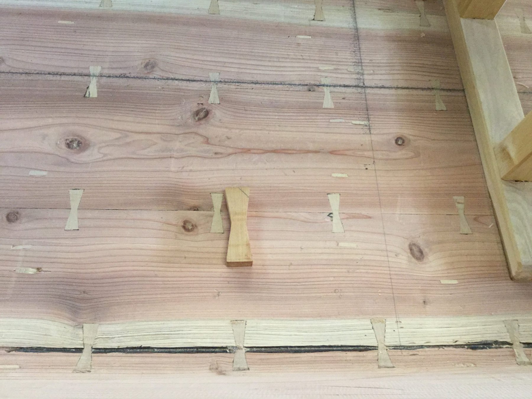
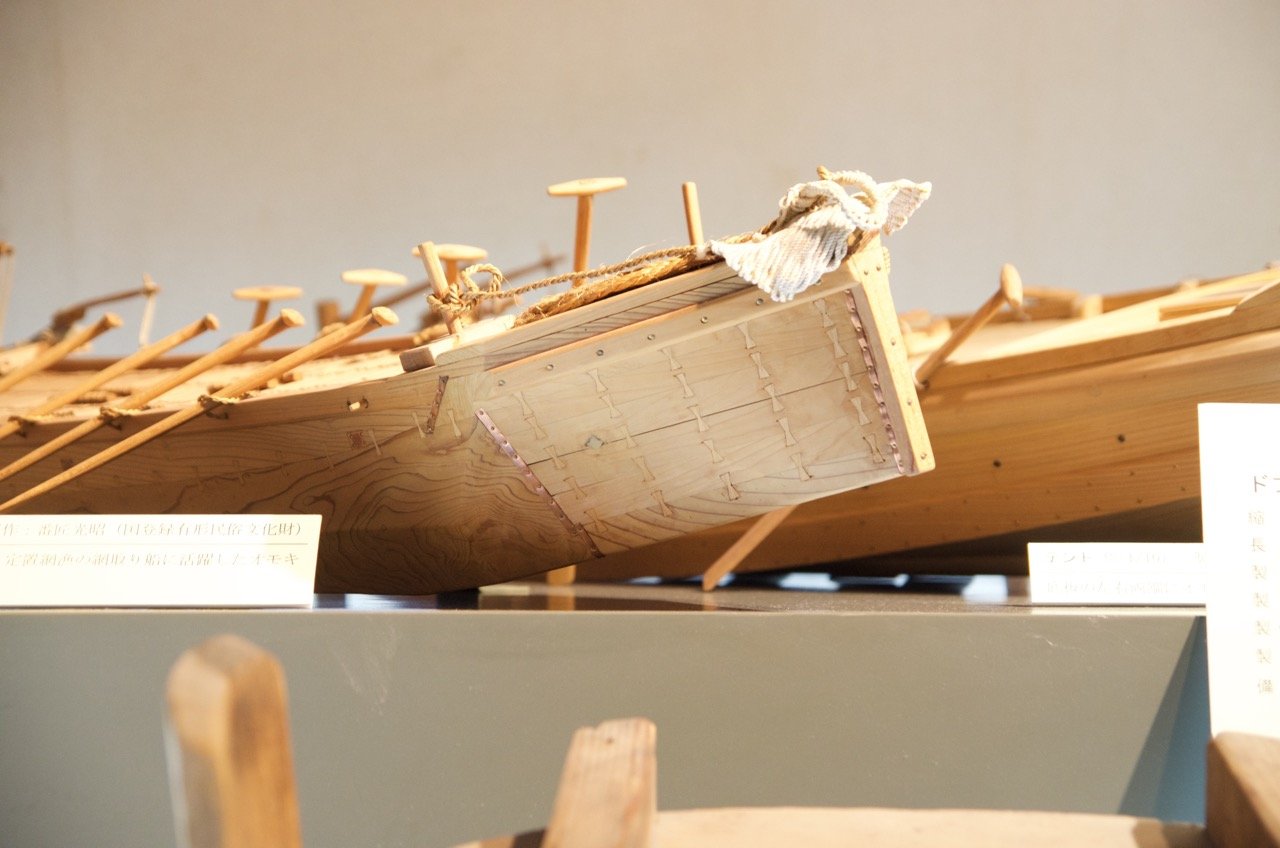
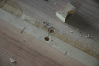
Hi Dan, Good question. On one boat in particular, I have had that same question. But, on these boats, I'm sure the planking is too thick to run the fasteners all the way through. I believe they're about as deep as that large fastener sitting on top of the wood in that last posted photo. So, the fasteners would have to be added to both faces of the planking. I don't know if they are done inline or staggered or if they even worried about it. I'll ask Douglas about it. Been meaning to do that because of the Aganogawa-bune, or Agano river boat, which is a beautiful, slender boat that his students at Middlebury College built a replica of. Here's a photo from his blog, where he basically answers this question. A mortise is cut for the fastener, in this case, to the thickness of this fastener. Douglas Brooks has a great blog site, which I think people here would really enjoy. Here's the entry for the fastener, which he refers to by the name used by his teacher in Okinawa, a huundu: http://blog.douglasbrooksboatbuilding.com/2009/12/huun-du.html Oh, I just read in the blog that his teacher in Okinawa like to lay these out with an even stagger between the inside and outside. A very useful blog!
-
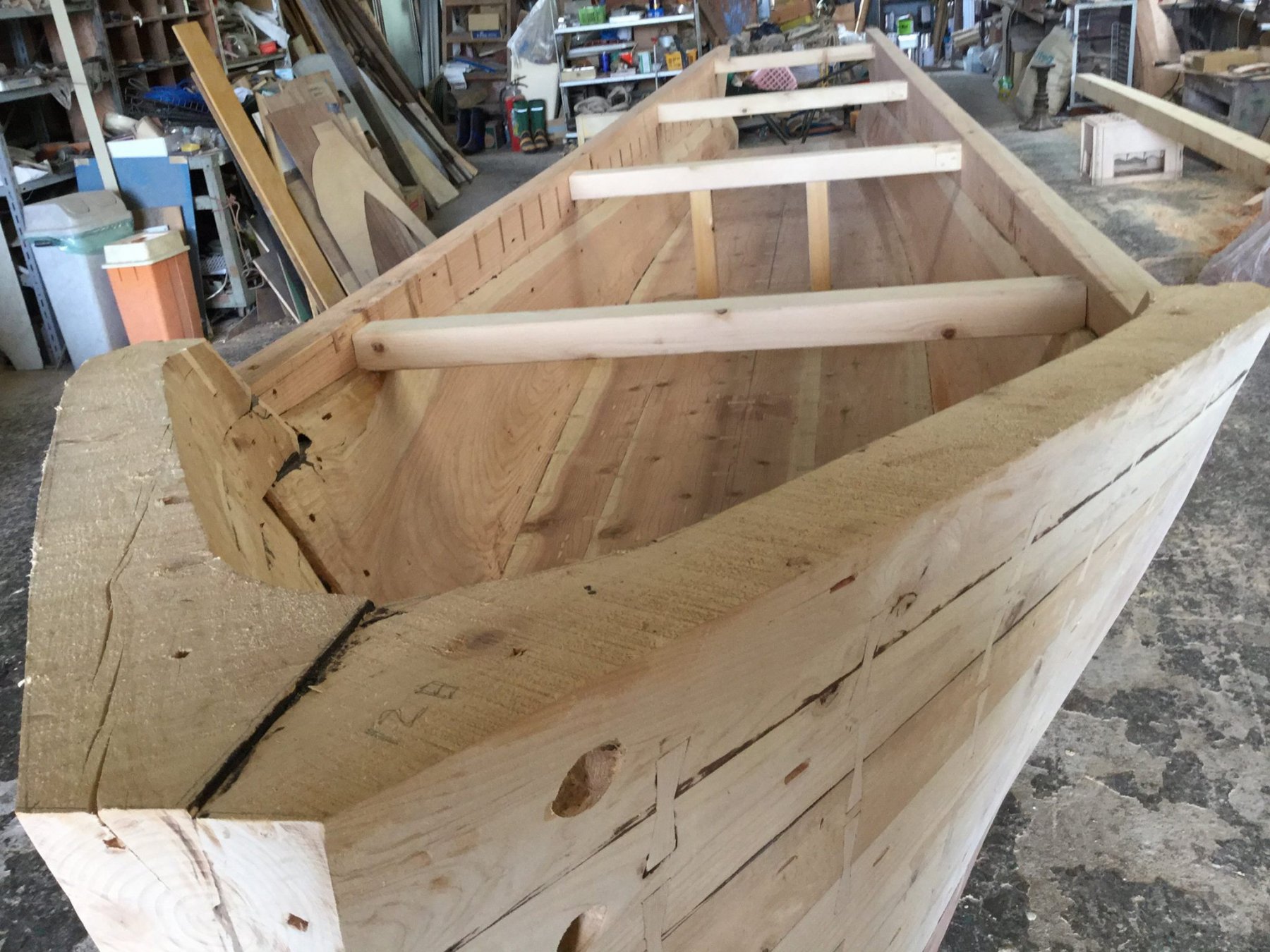
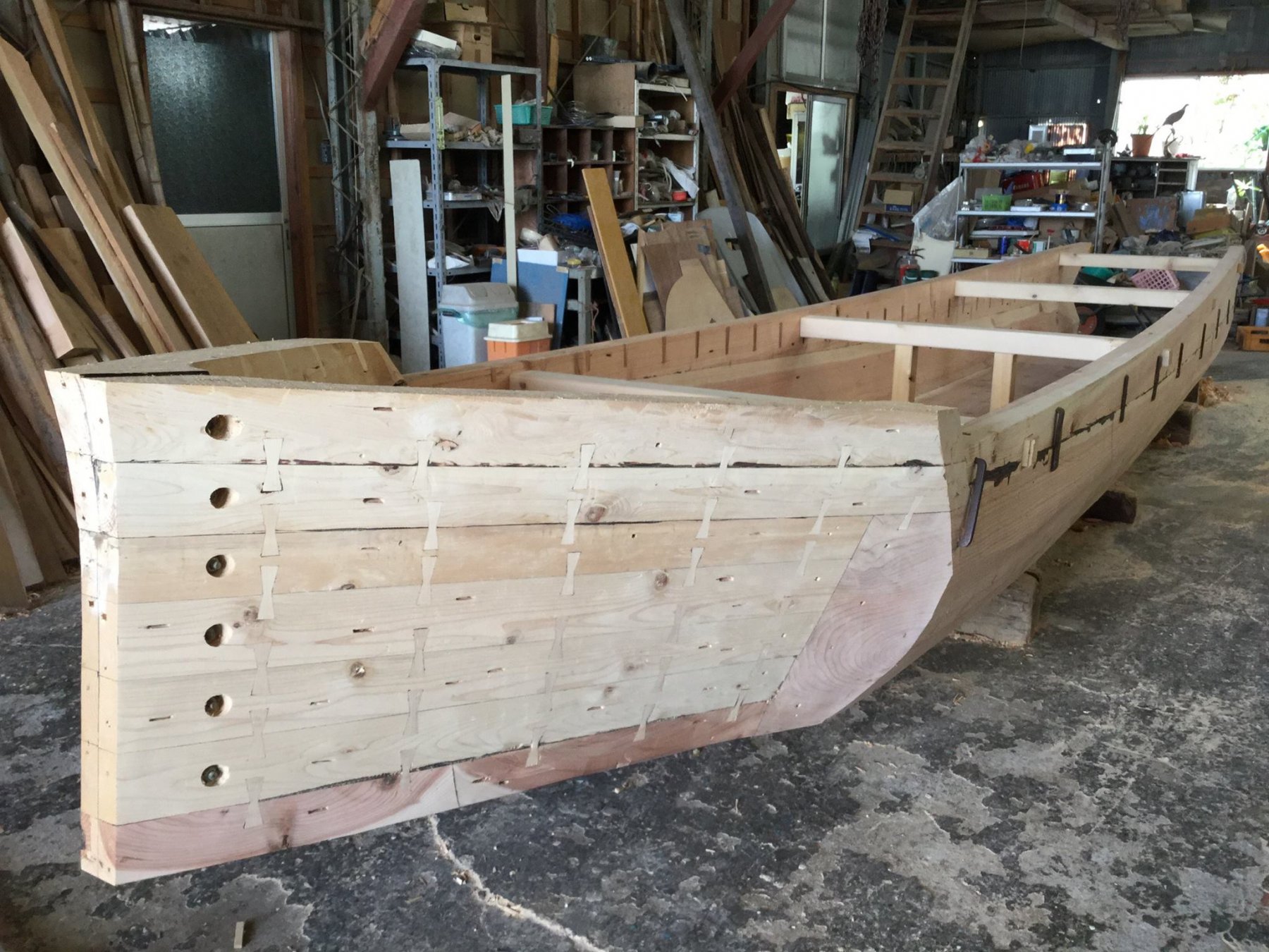
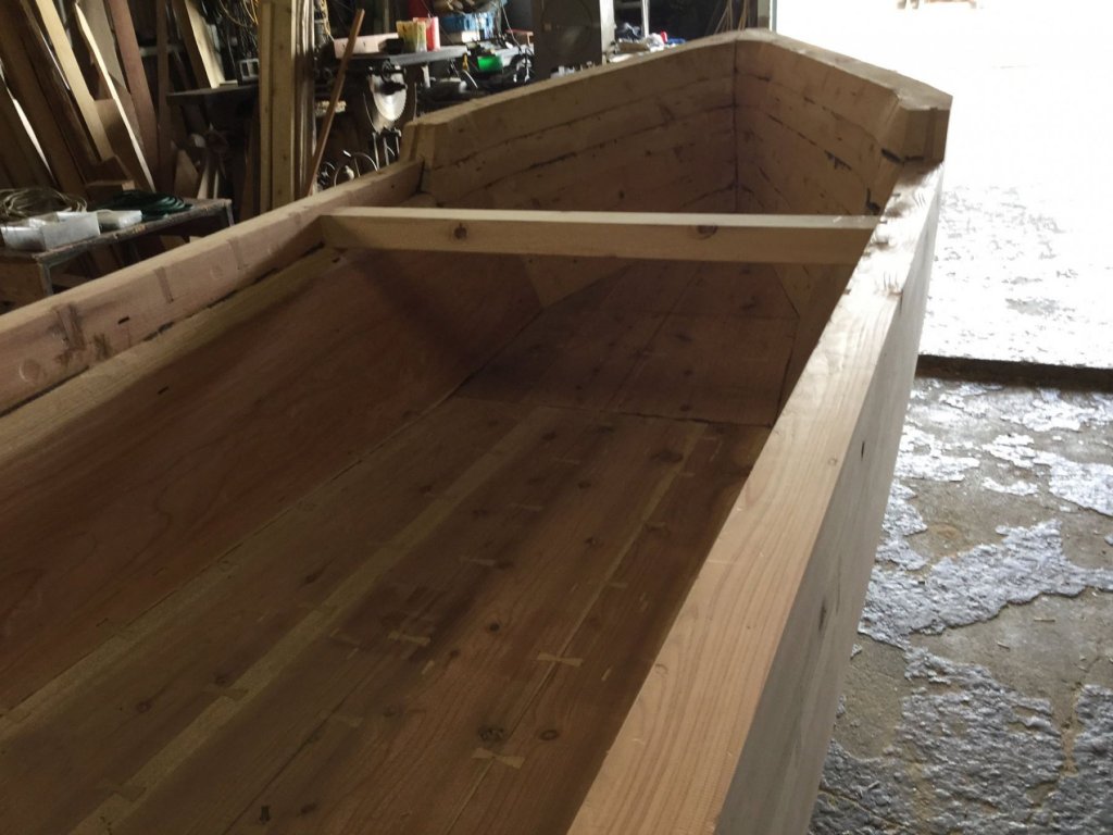
Okay, one last post about the Dobune. I found a few photos of a half-scale replica being built. The photos were on a Facebook page for boatbuilder Nasu-san. I don't recall his first name. He instructed Douglas Brooks on the building of a Ukai-bune, or cormorant fishing boat, earlier this year. Some of you who attended Douglas' talk in Mystic a couple years ago may also recall seeing a short video of Nasu-san pounding nails with a lively rhythm. I don't believe Nasu-san is building this replica, the photos were just on his page. There are more photos on Nasu Boatbuilding's Facebook page, if you're interested. It's in Japanese, though, but you'll find them in the Photos section: 那須造船 Note how the thick lower hull plank is actually more of a carved log. This type of construction seems pretty rare, and I believe it's considered a transition between the semi-structure hull type, as shown in my umibune model, and a structured, or fully planked hull.


-
Beautiful job on your build, Art! I really like this kit – I have one up in my closet I've been saving for a rainy day. It's too bad these kits are out of production. Great blogging too!
-
Hi Dan, It's great to see you here – by all means pull up a chair. Thanks for the nice comments. Funny thing is that it often FEELS like I'm trying to figure out a puzzle box... Ken, I was originally looking at taken on a different boat to model, a net-fishing riverboat used on the Agano river in the Niigata prefecture. It uses a lot of those fasteners and I couldn't manage them in the small scale and type of wood I wanted to use, they were too soft. So, I turned my attention to the Kamakura period sea boat at 1/50 scale. Most wasen models in Japan are either sugi (cedar) or hinoki (cypress). But, looking at the Dobune in that photo, you can tell from the wide, wavy grain pattern that it's a different wood. I suspect it's a much harder wood, which I think you'd need in order to cleanly use fasteners like that. I do want to experiment with modeling this feature at some point.
-
Hi jct, Sorry I'm late to the party! I'm really glad to see another Shipyard build. I saw this in the shop a couple months ago and had to slap my own hand to keep from buying it. It's a very nice looking kit and it looks like you're doing a great job! Thanks for the nice comments earlier. I don't think I deserve them, but I really did have a LOT of fun building one of these paper kits. Thanks for the tip about the punch. I've heard of others using and recommending them, but I still haven't tried one out yet. But, I know that you'll get much cleaner rounds with one. I'll be following along, but everything is looking great!
-
Mark, who says it's unavailable? Billing Boats USA has them in stock, and they're still listed on the Billingboats.com.
-
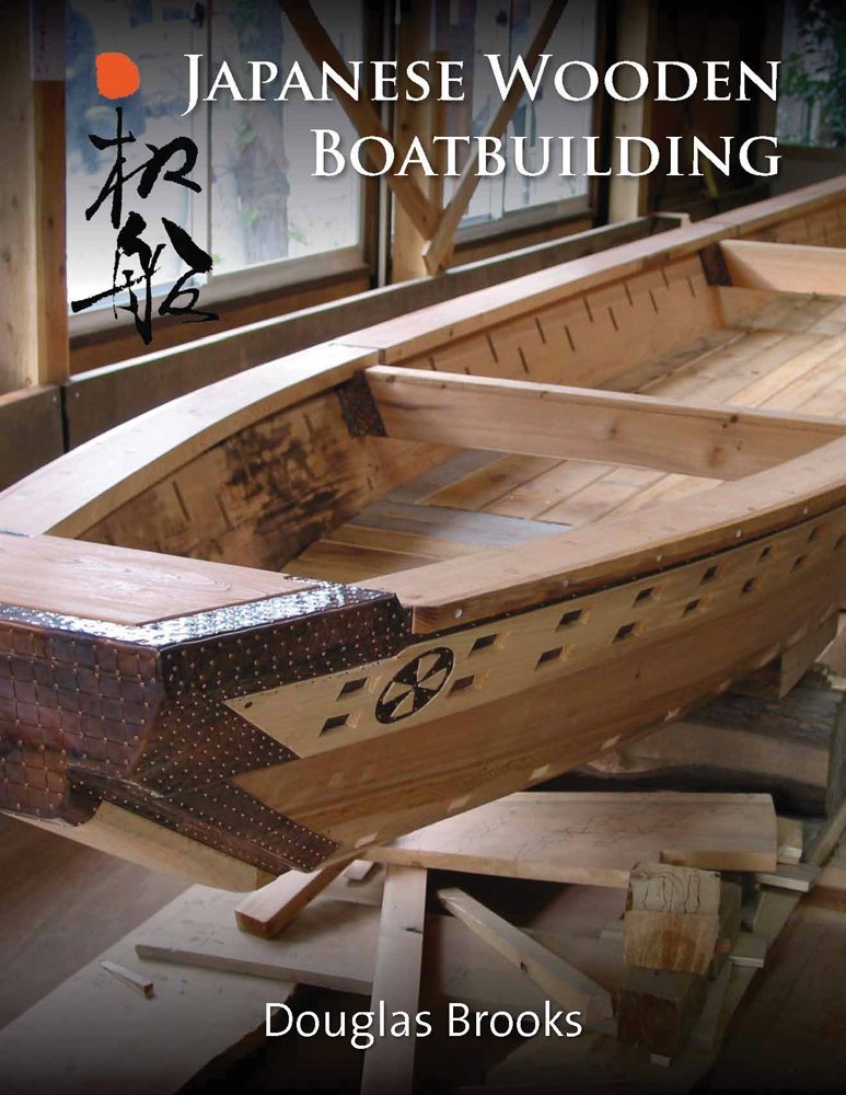
Ken, if you like those fasteners, you'll love this boat. It's a kind of semi-dugout called a Dobune (doh-boo-nay). The were used up until the 1960s, I believe, off the Noto peninsula in the Sea of Japan. This is only a model of one, but take a look at the bow. The photo is courtesy of Douglas Brooks, who took it when he was in Japan working on a boatbuilding project in Himi last year. And Carl, since you mentioned his book, let me take the opportunity to plug it here! This is a "must have" book if you're interesting in Japanese traditional boats. I can't recommend this book enough. It's not a cheap book, but it is loaded with information and it is written in a style that makes for easy and fascinating reading. If you're interested, I recommend buying it direct from the author off of his website as it helps to support his research work: http://douglasbrooksboatbuilding.com/japanese_wooden_boatbuilding.html