
Bedford
-
Posts
1,284 -
Joined
-
Last visited
Content Type
Profiles
Forums
Gallery
Events
Everything posted by Bedford
-
 Cherub is beautiful Mark and looks perfect under sail. I know the Karoo will be a beautiful model well received at the club no doubt. I would love to work with some nice huon pine, maybe one day.
 -
The idea is that once you start with epoxy on ply you may as well keep going and seal the whole thing completely. Apparently varnish is not guaranteed to seal completely but three coats of epoxy will and it's a lot tougher than varnish however. as stated, epoxy needs UV resistant varnish or paint to protect it from the sun
-
Well since you asked, the recommended method with the bote coat epoxy I used was to re-coat while the previous coat was still a little tacky which ensures the best bond. Having said that don't panic because if you couldn't do that they recommended sanding with coarse paper between coats to give a better surface for bonding. What I have read in wooden boat building forums is that the epoxy you are using will get what they refer to as an "amine blush" when it cures. This is a result of the chemical reaction and must be washed off before another coat of epoxy or paint is applied. So, knowing what I now know, I would suggest:- 1- wash the epoxy with soap and water and rinse well 2- sand with 120 grit wet and dry WET, you'll be amazed how well it works once it starts building up a little sludge 3- rinse again and when dry apply more epoxy Don't sand too much between coats but try and get it a bit even because epoxy tends to run a bit and you will get very thick beads of the stuff that will take a lot of sanding to remove later. I know it's difficult but try and get it on there as thinly as possible to reduce runs
- 299 replies
-
- 11
-

-
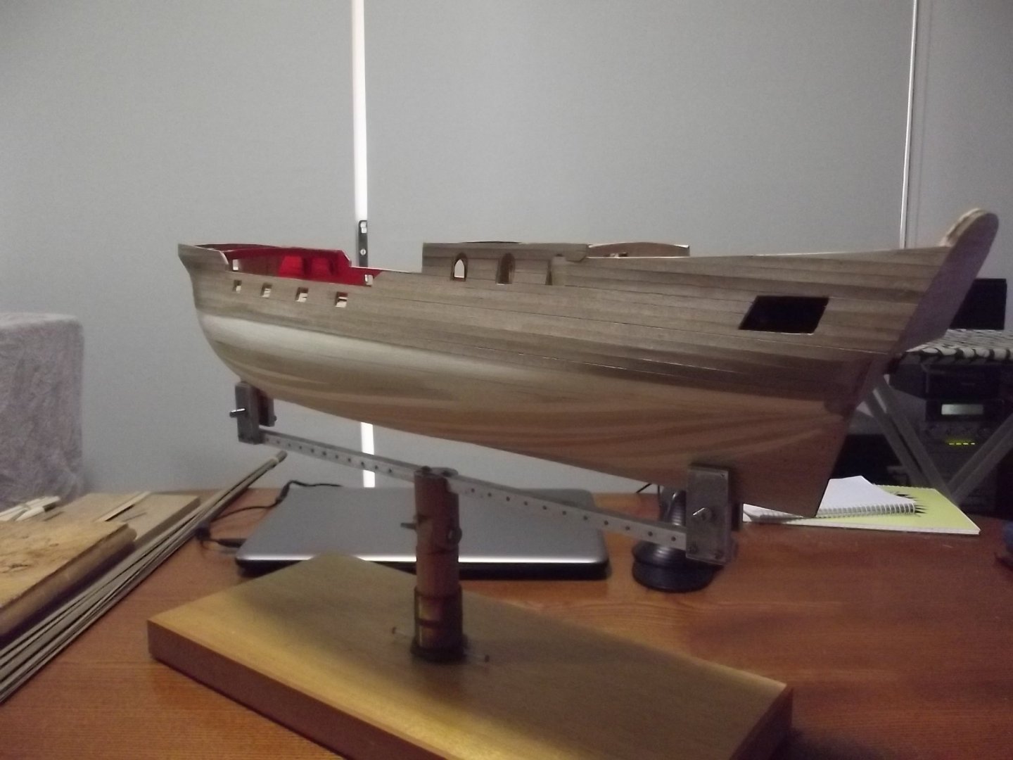
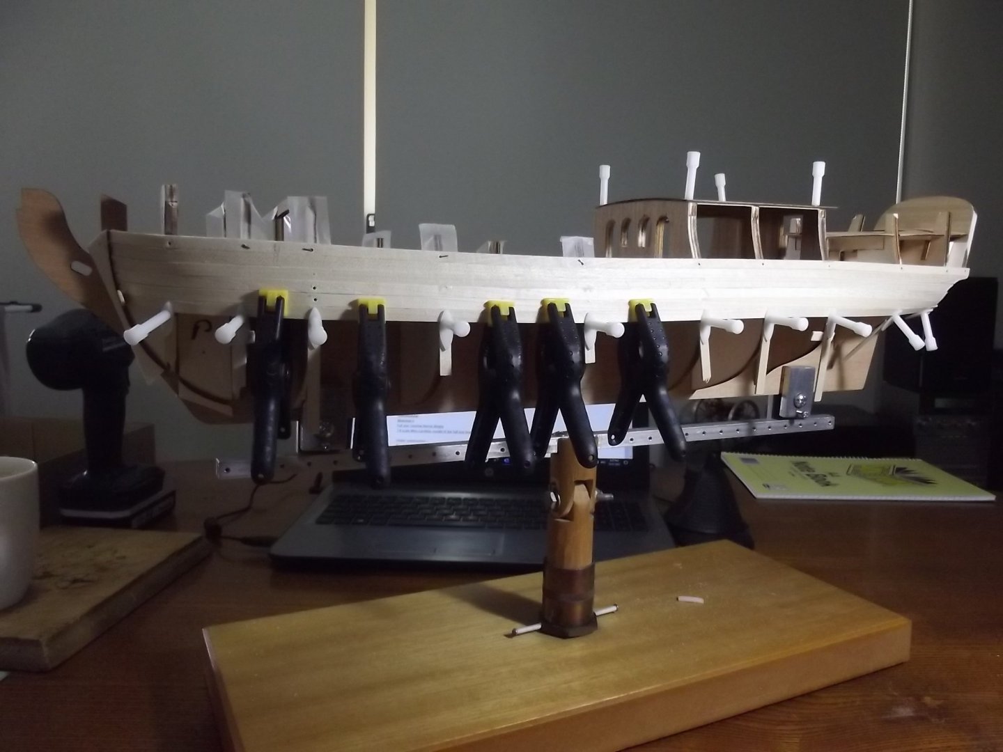
I've been working on the second layer of planking, so much nicer than the wood provided in the kit. I've planked the quarter deck but am working up the enthusiasm to do the main deck because it's going to be challenging to fit the margin boards and joggle the deck planks in but I'll have to get into it soon

-
I've sailed on the replica Endeavour, similar age design, and the access to below decks is covered, 1.4mtrs would be about the height. I'm about 1.9 tall and access was easy because you always face the stairs. Also people 200 years ago were generally shorter than todays average.
- 124 replies
-
- 1
-

-
- panart
- royal caroline
- (and 1 more)
-
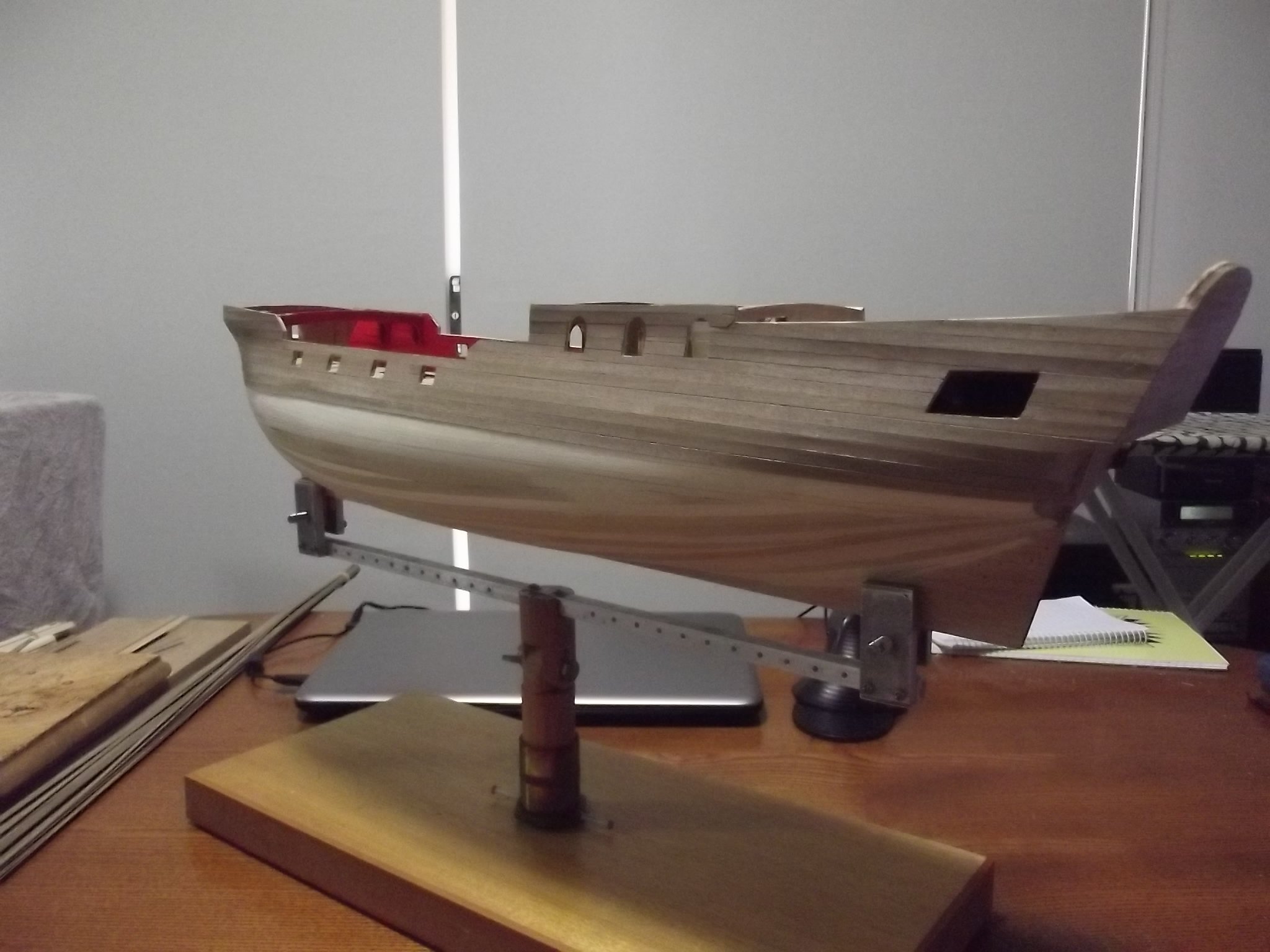
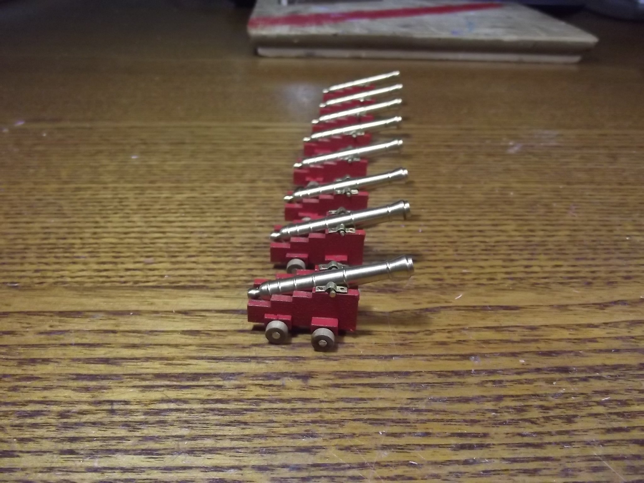
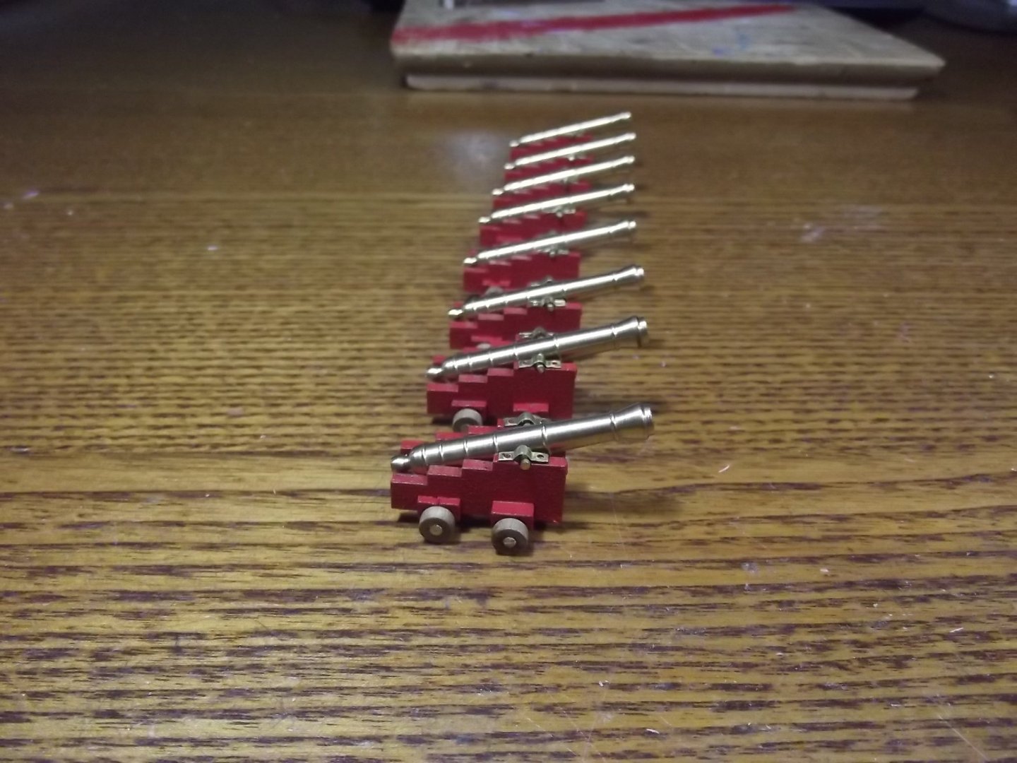
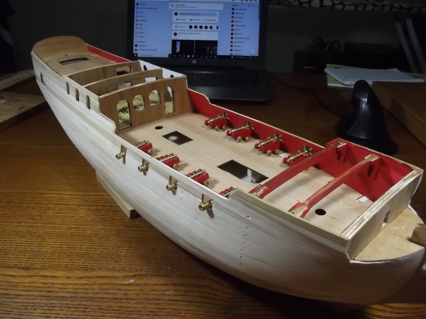
First layer of planking completed but the material provided for the second layer was so bad I threw it out and am waiting for better stock to arrive. Meanwhile I've painted the bulwalks red, and made the guns so I could make sure the gun ports were correctly placed
-
I've not long started my RC so I'm following yours with great interest
- 124 replies
-
- 1
-
-
- panart
- royal caroline
- (and 1 more)
-
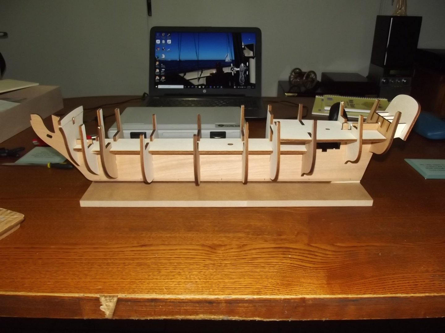
Well I did my due diligence and determined that the mast holes are not as badly aligned as suspected, we're only talking a degree or 2 so I can easily rectify that when the time comes to step the mats, there was a bit of an optical illusion going on apparently.
-
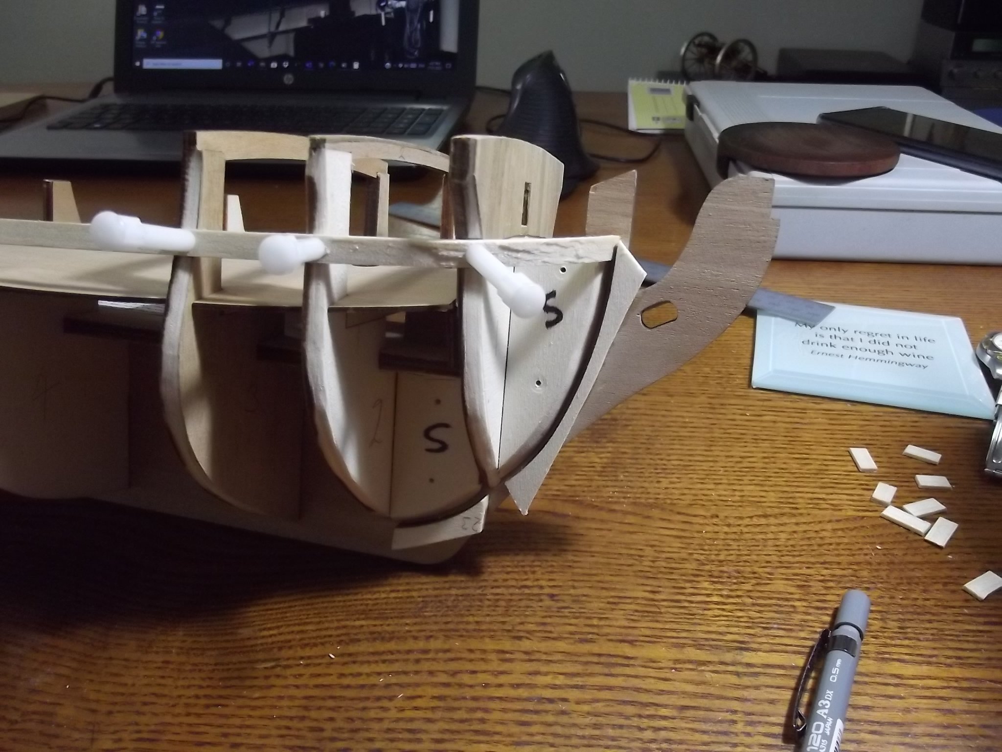
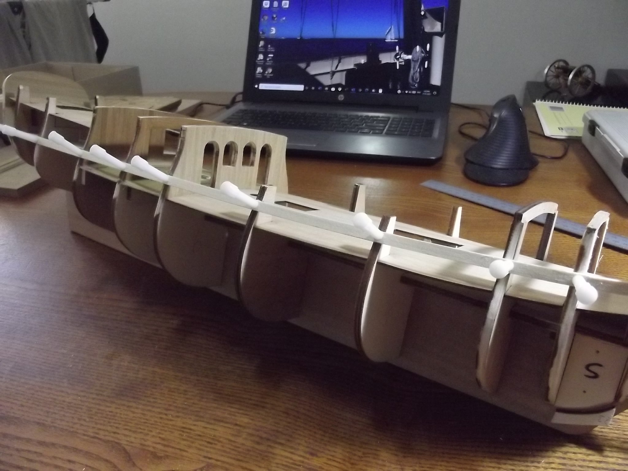
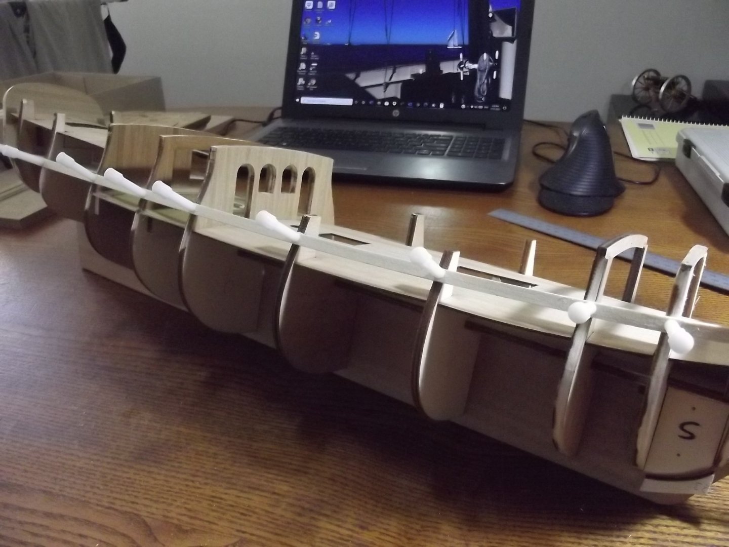
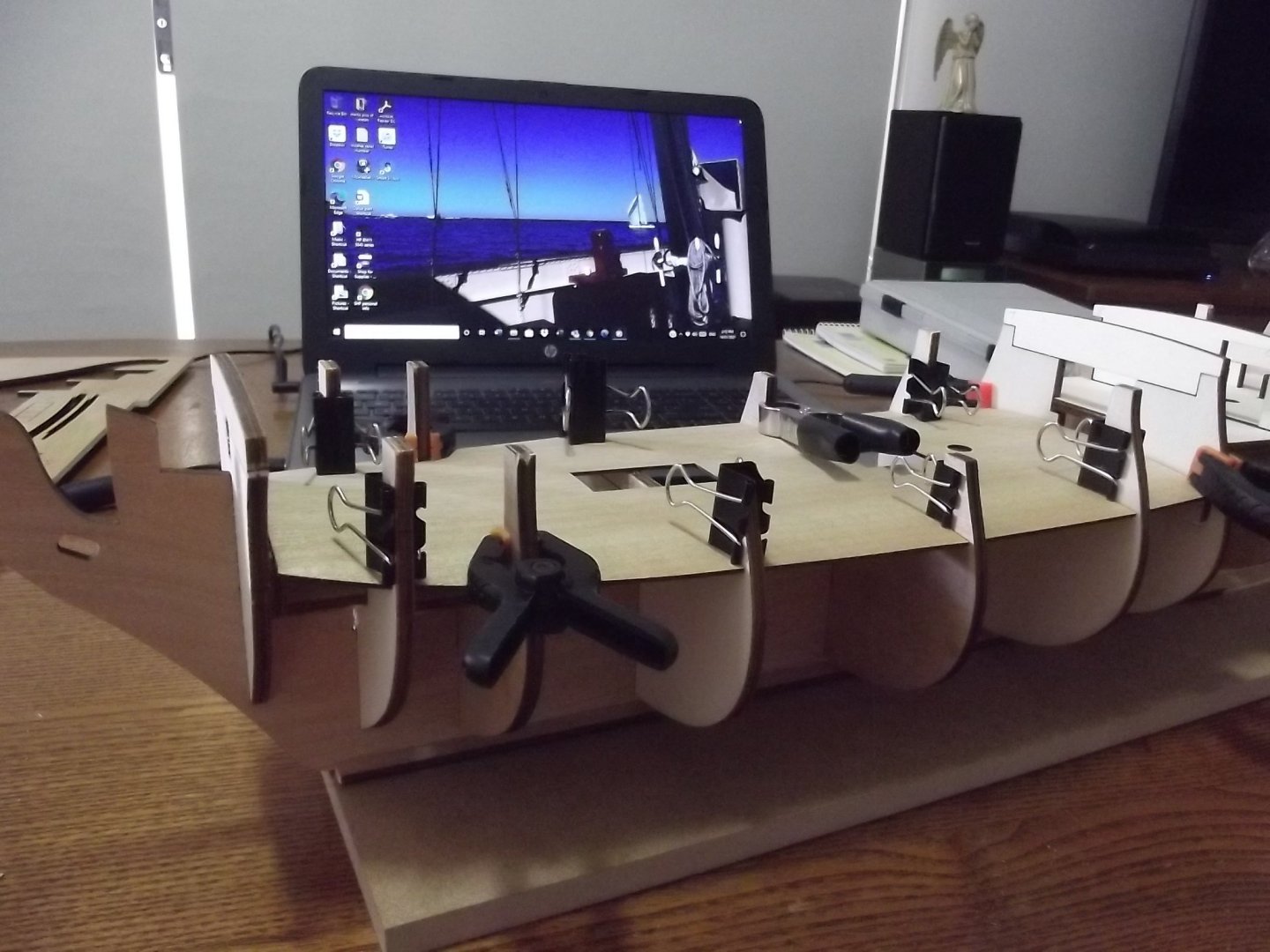
The planking begins, you'll note that I glued the "negatives" of the bow molds to the stem to provide proper placement and wedging facility to keep the planks held properly at the bow. They will be easily removed later with a sharp chisel. I've got 6 planks on each side but here it stops for a while because I don't like the alignment of the mast holes. The fore mast will lean forward like an older VOC ship, the main will be vertical and only the mizzen will have a gentle rake aft like it should so now I have to take the angles off the plan and work out how to make it all work. This is the first kit I've had which doesn't include the mast angles.

-
On the topic of epoxy grease, yes I've experienced that on my boat in very upsetting places that took some effort to fix. My solution was not to rely on clamps to prevent movement, rather I doweled the pieces so they couldn't slip or I screwed them on while the epoxy set. Some screws I removed and back filled with epoxy and some became a feature of the boat because they were in places I didn't want visible epoxy hole filling. I used silicone bronze screws so it looks good and won't rust. If you use screws you can wipe a tiny amount of vaseline or similar on them so they release or if you time it right you can unscrew them once the epoxy has hold but before it sets completely OR if they can't be undone simply heat the head with a soldering iron to warm the screw until the epoxy will release it. As for the patch, yep just fill it with thickened epoxy because it's structural too.
-
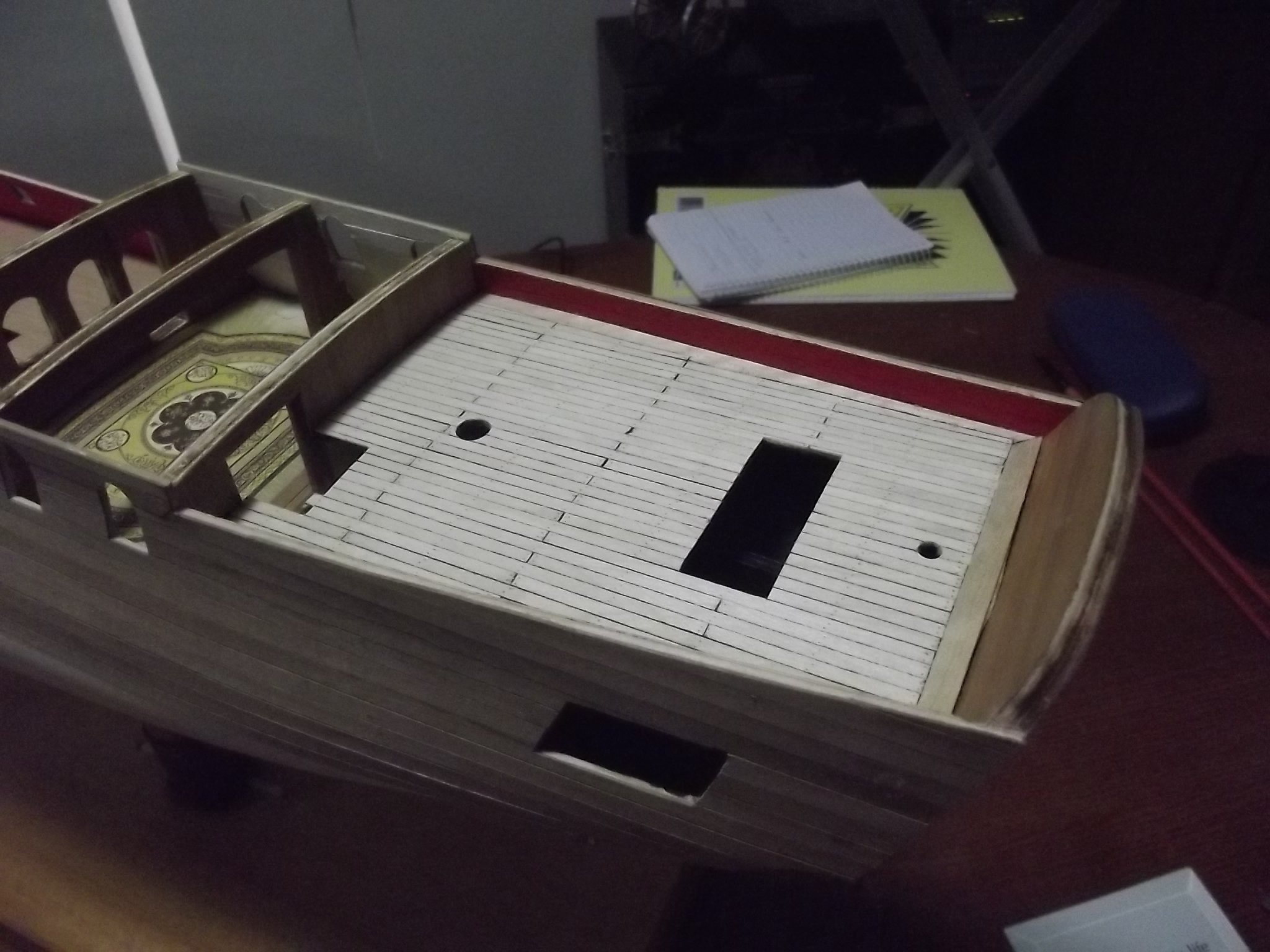
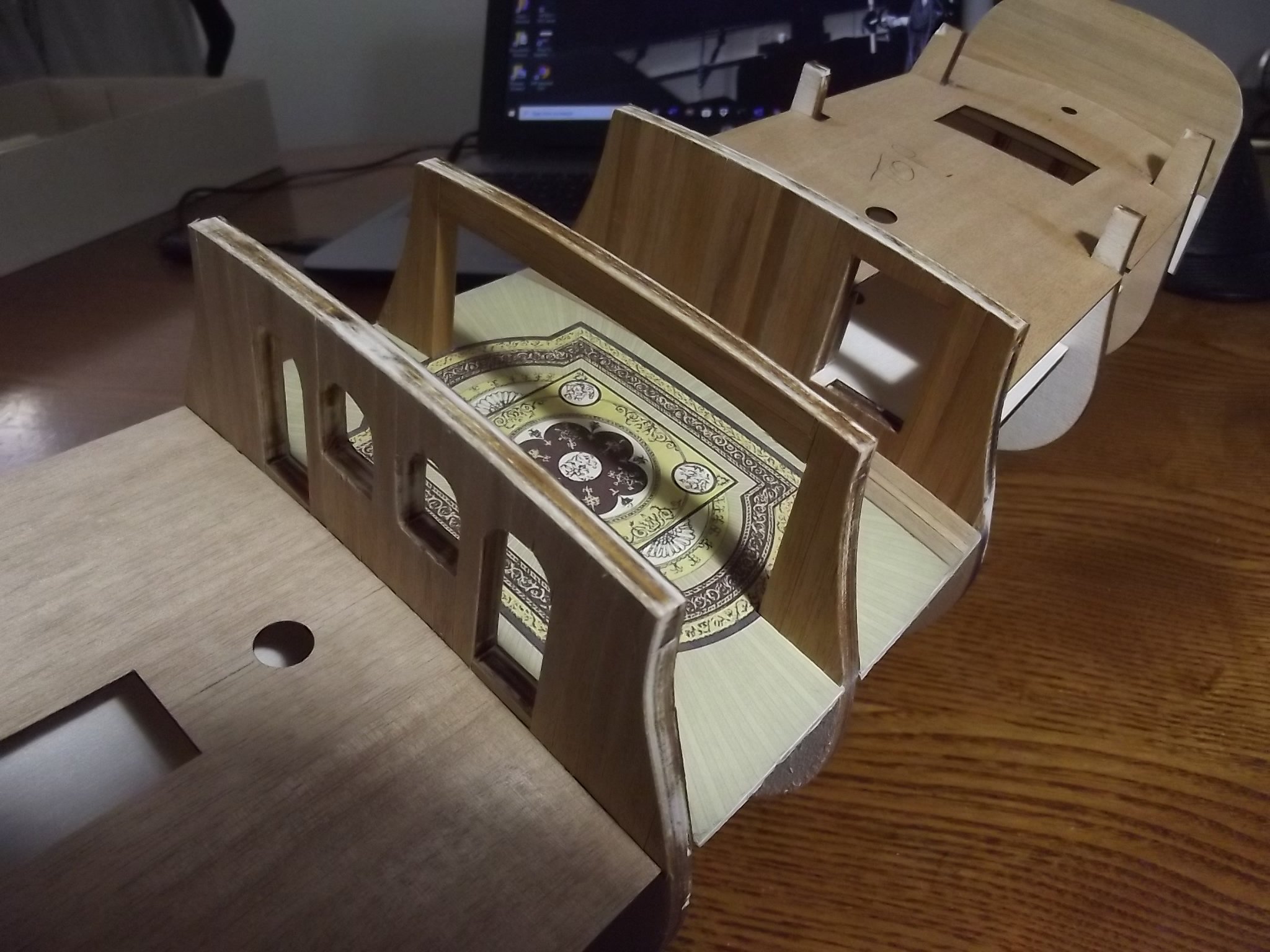
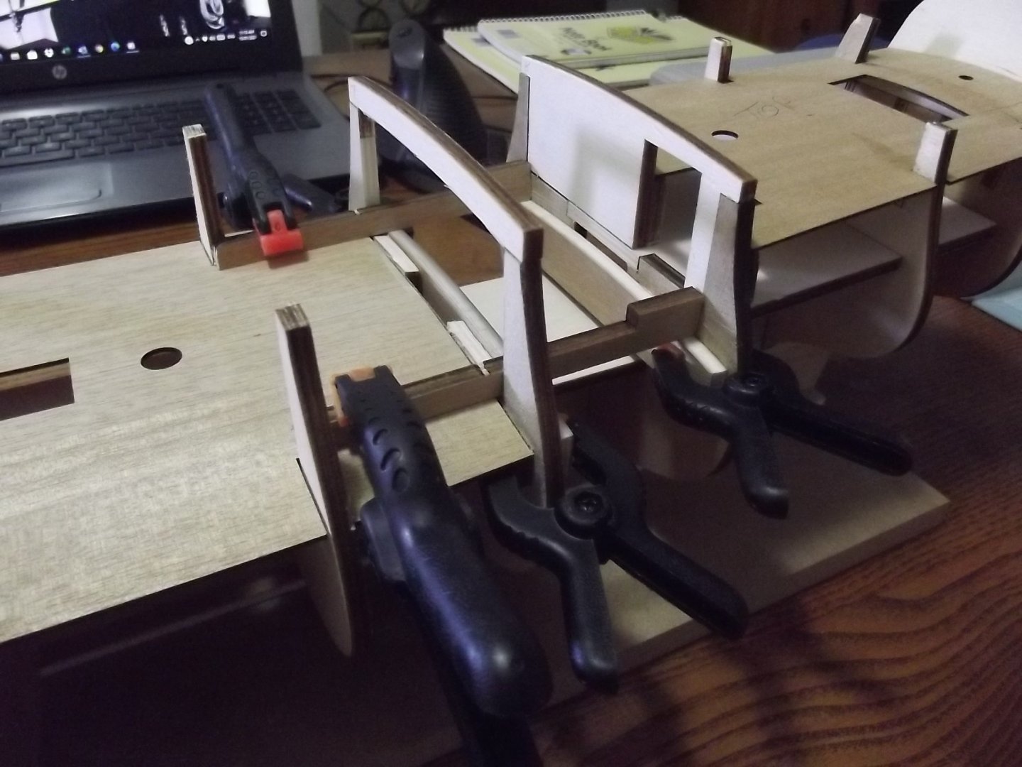
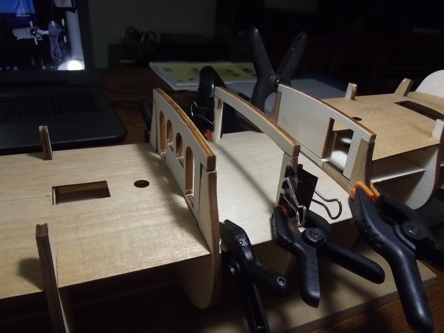
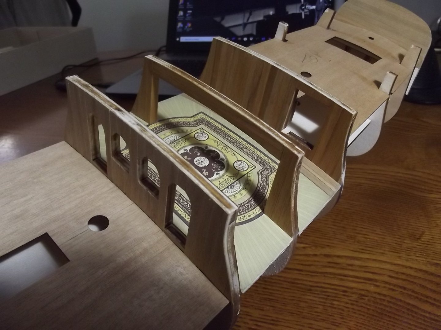
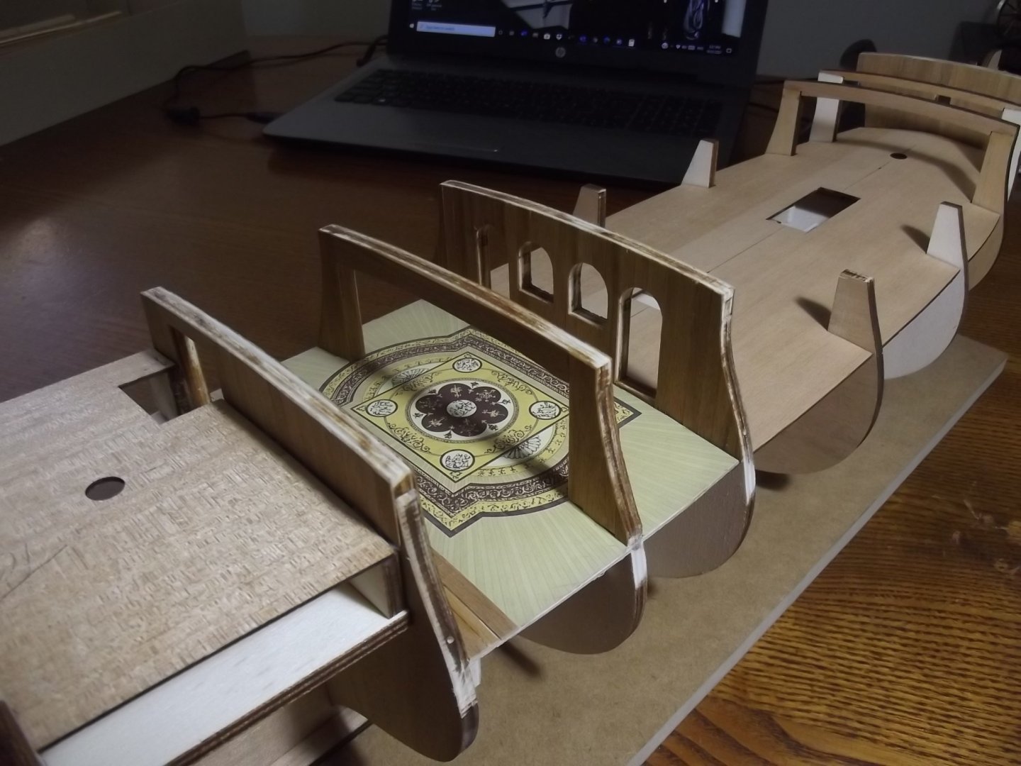
Ok, this will be a tad long winded. Several years ago I was googling this model and stumbled upon a build on this very forum (that's how I came to join this little group) where the builder had taken the time to research and draw up the floor of the Kings cabin on his computer and the pics where beautiful so I asked him if he would be so kind as to send me the artwork and given my reason for building this he was more than willing to help. I don't remember who he was and as far as I know the build thread was lost when the site crashed a few years back. Anyway, I am proceeding with my plans to fit out the Kings cabin. I cut out the centre of frame 7 and traced the floor beam at that station to put one on the back of 7 and another on the front of 8. To align them I just clamped some scrap to the existing floor section between 6 and 7 and used them as guides for the two extra floor beams. I then cut a template for a new floor to cover the existing half floor and the new section aft of station 7 and cut the new floor from some 0.8mm ply and glued that down followed by the floor image. I then lined the interior timbers with some 6 x 0.5 planks I had. There will be more in that cabin as time progresses. On the subject of lining walls etc I differ from the kit manufacturers in that they recommend applying the facing planks AFTER doing the hull planking but it is so much easier to do all the surfaces that can be done prior to hull planking because you can just slap the planking on then with a sharp chisel trim to an exact fit without any drama.
-
OK, I'm no expert but I've been through the process. The epoxy resin is naturally quite thick so you can't really put it on thinly, having said that you can thin it with metho (you're an Aussie so you know what I mean) but it thins by way of spreading the stuff and creating micro pockets between epoxy bits and when it evaporates it leaves micro gaps in the epoxy which allows water to get to the wood. The Aussie epoxy I used has the option to thin the first coat with a rot resisting thinner designed to allow it to penetrate more and it doesn't leave the gaps because it's epoxy based. I don't know if it is available elsewhere or if it works with other epoxies because the stuff I used is very low in toxicity.
-
As Oddball said, "have a little faith baby, have a little faith"! It does get easier but it's a very steep learning curve and the mistakes take a lot of sanding/filling/elbow grease to fix but you'll get there. You might want to have a look at a product called Peel Ply, it is for use with epoxy and is laid on over the epoxy and smoothed out, in theory as I understand it, the epoxy adheres to the ply in a surface tension way but not a glue way so you peel it off after.
-
Thanks Chris
-
Well folks I've been sitting on this one for a few years now. I had always planned to build it for my daughter, Caroline. Before I got anywhere near buying the kit I lost my beautiful girl in a horse riding accident, that was in 2005 and she was 13. I've had the kit now for about 6 years but haven't been in the right place (on a lot of levels) to do it but the time has come. There will be a few special little things done during the build and eventually my son will get the model. This is the first kit I've done in a while as I prefer scratch builds but we'll see how it goes. Bear with me, this may take a while. The keel was laid on 13/1/2021

-
Don't feel too bad, I had trouble dealing with the epoxy too although the hull on my boat is not fibreglassed. Remember that you can heat epoxy with a hot air gun to soften it so a sharp chisel can slice though it then you only have to do a little sanding. How much did you mix up? Did you try to do it all in one go? I think the trick is to mix small batches, work that in nice and neatly before making another small batch etc. The different batches won't be a problem as far as the continuous bond goes because it takes hours for it to go right off and as long as the previous patch is still sticky the new batch will bond to it properly.
-
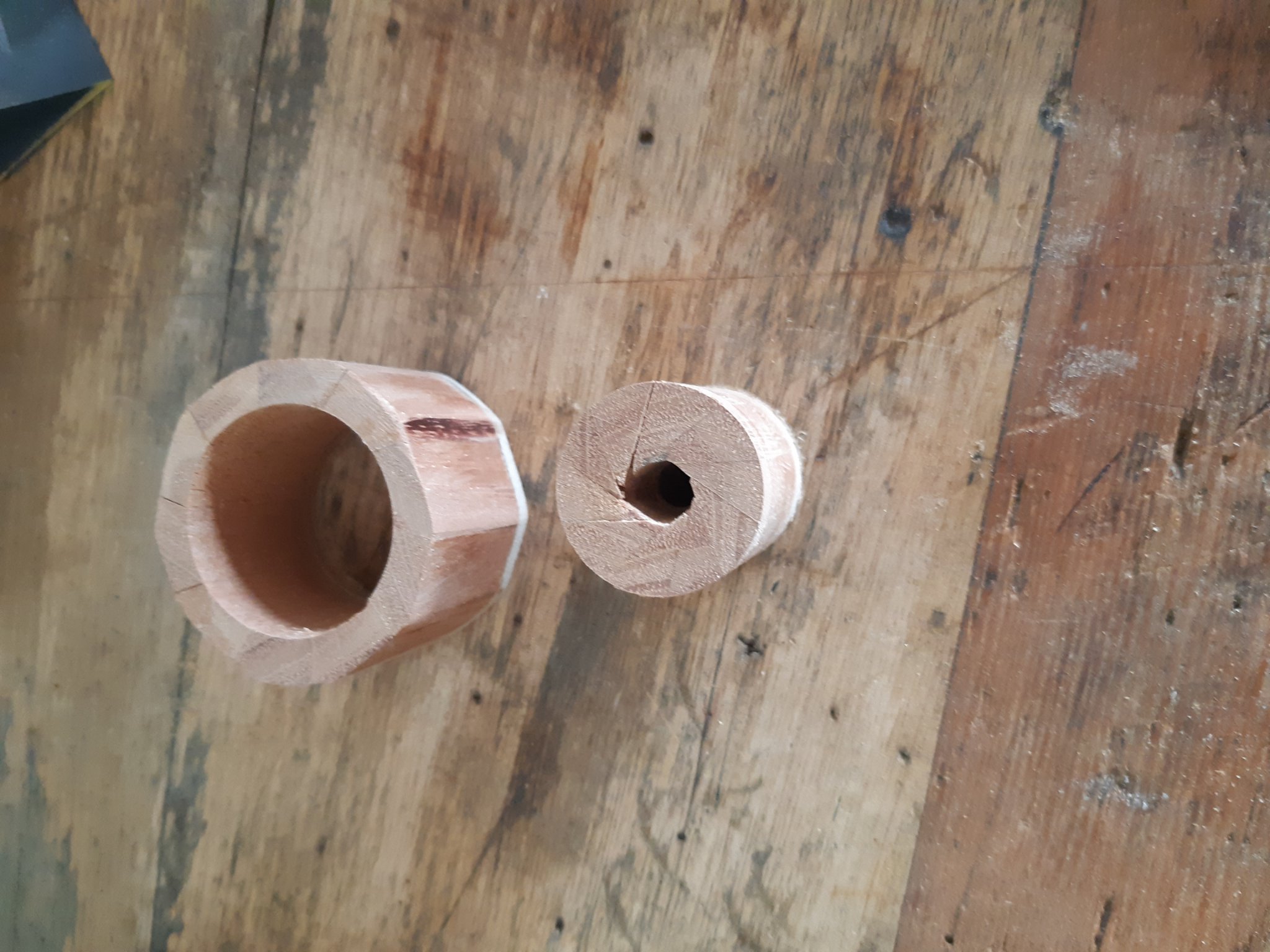
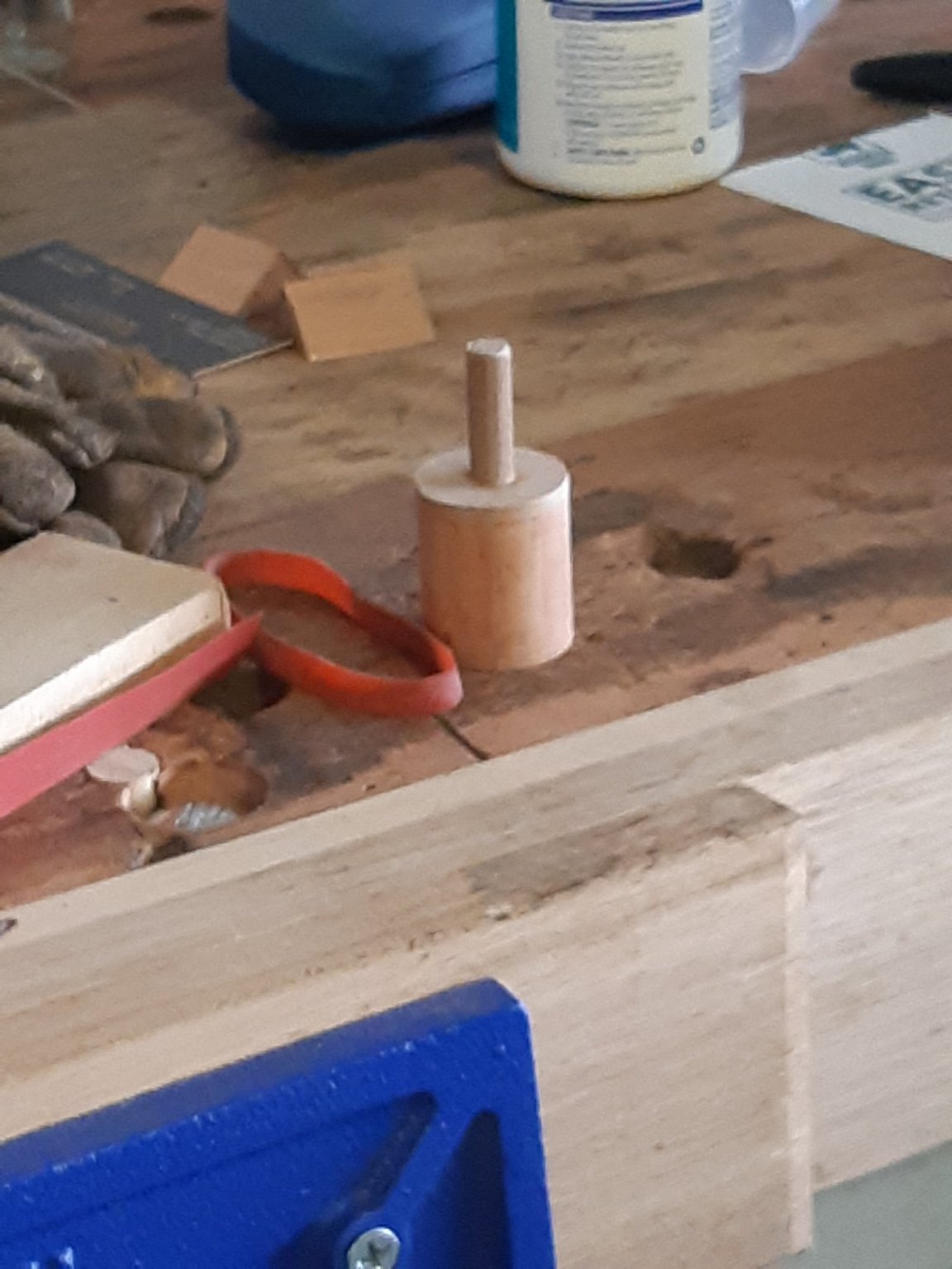
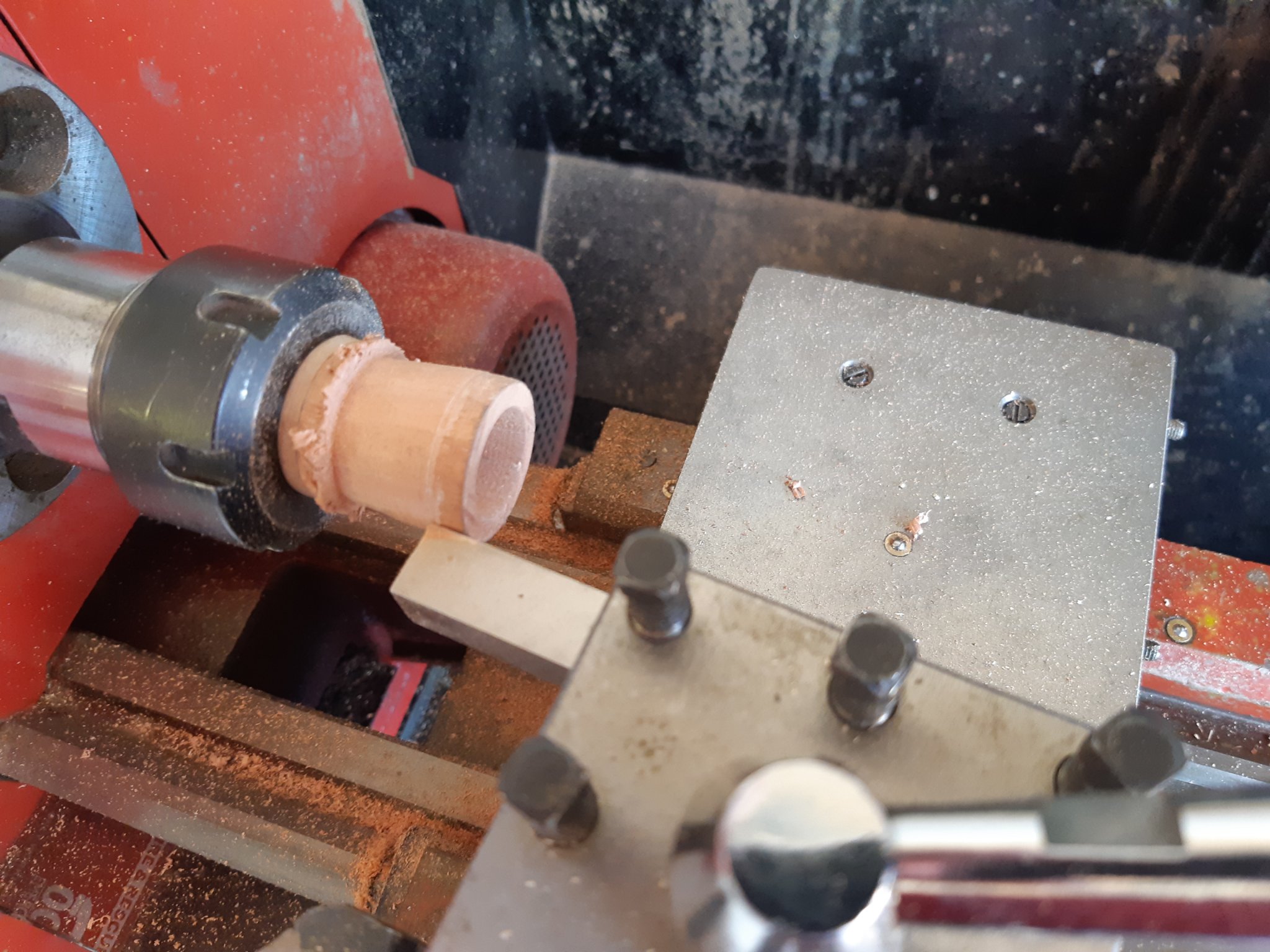
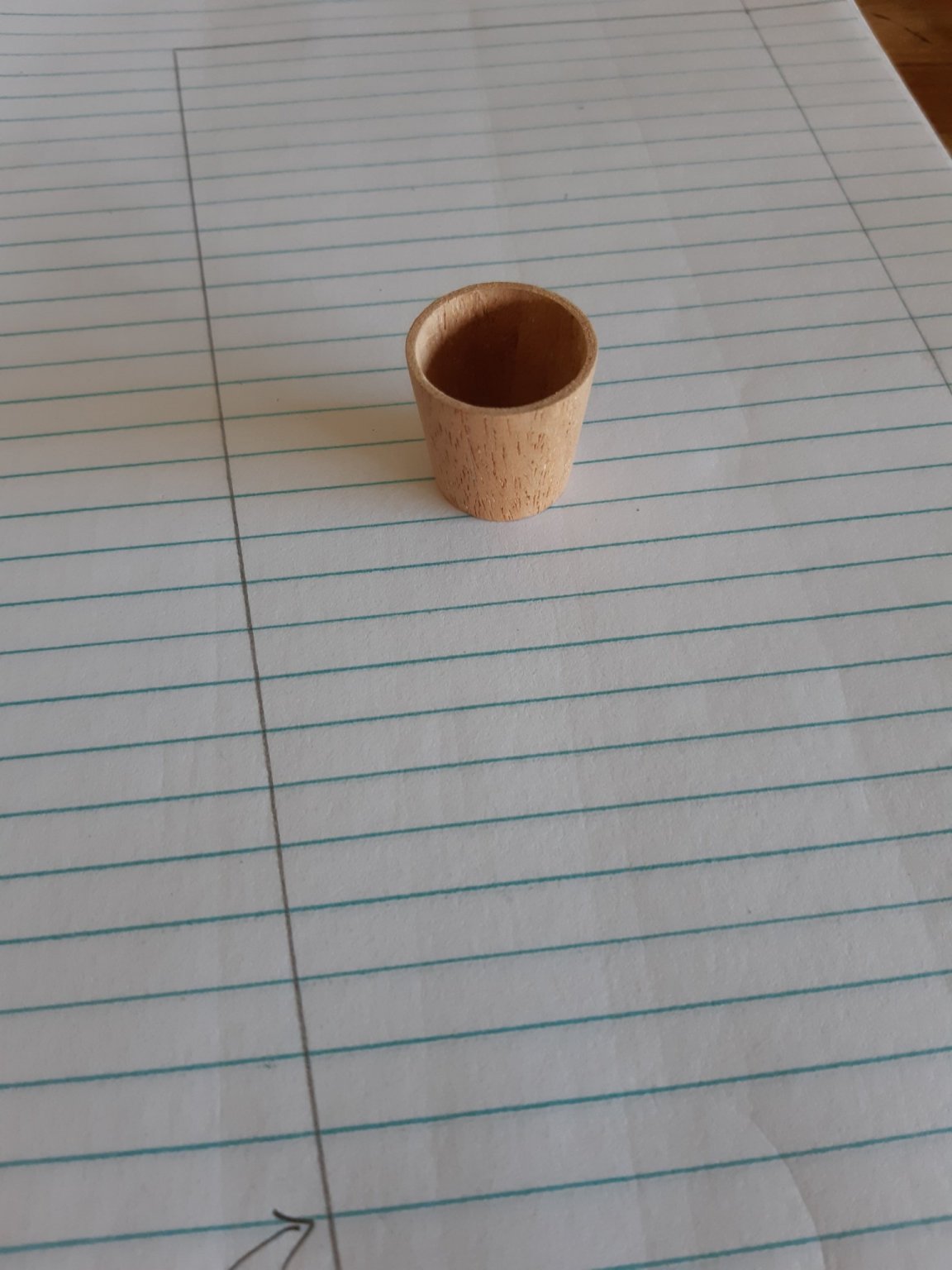
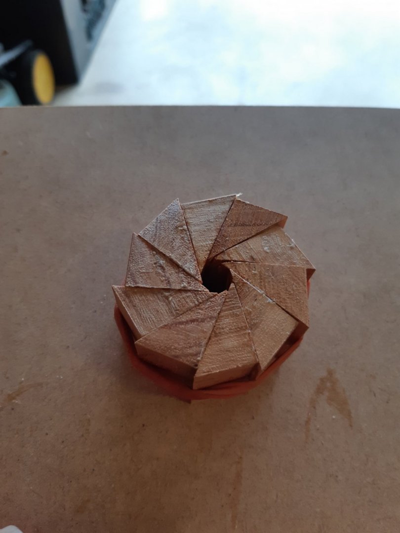
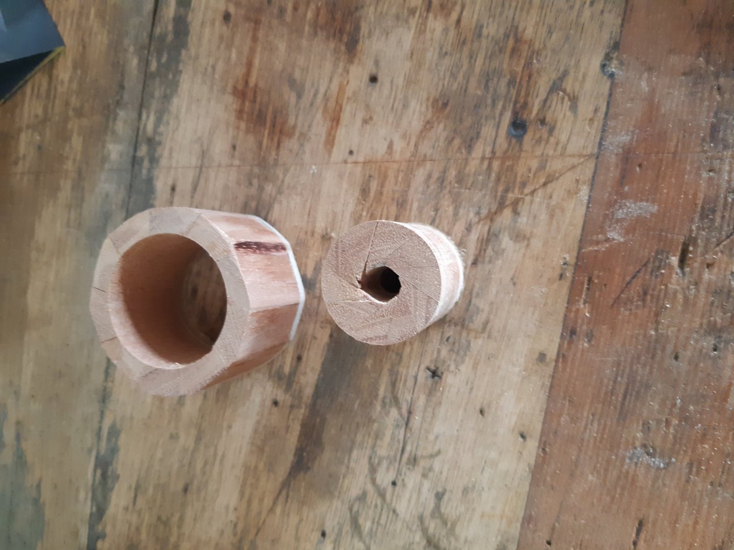
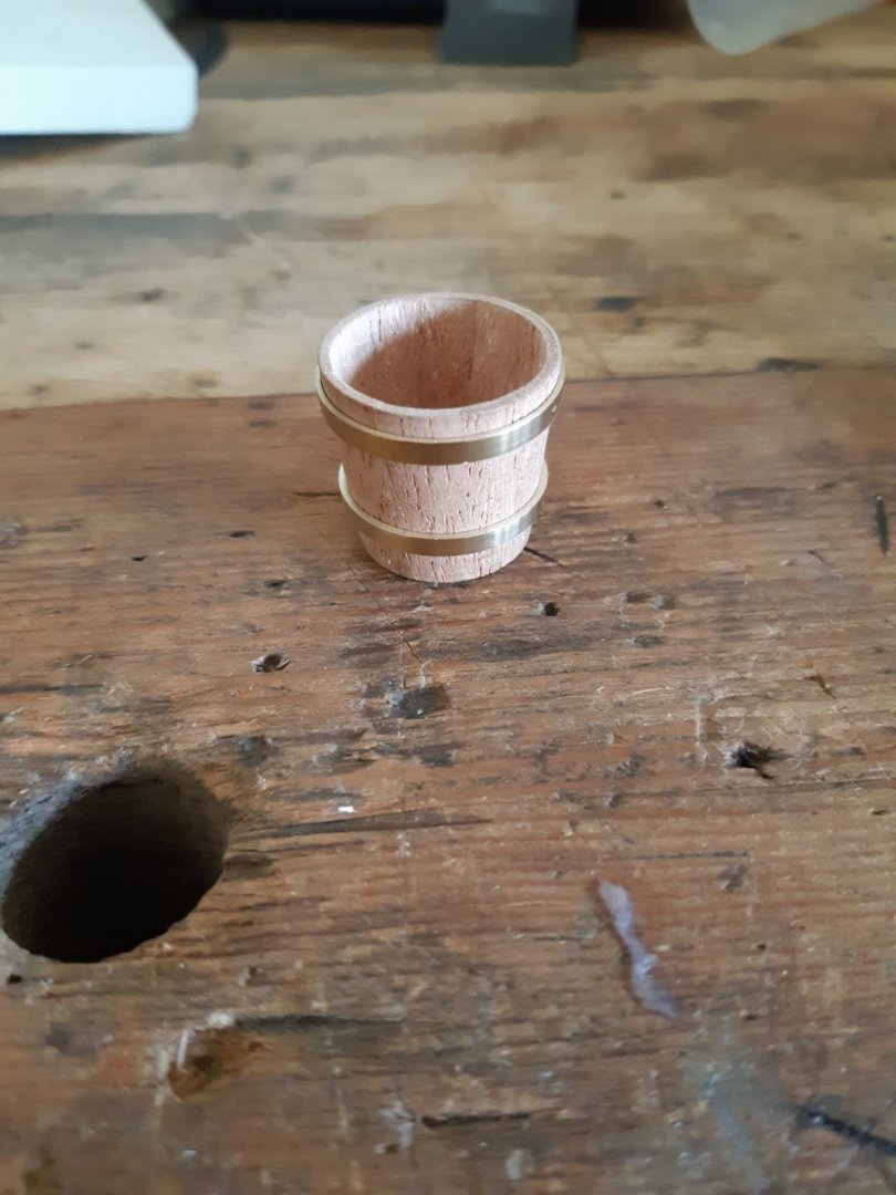
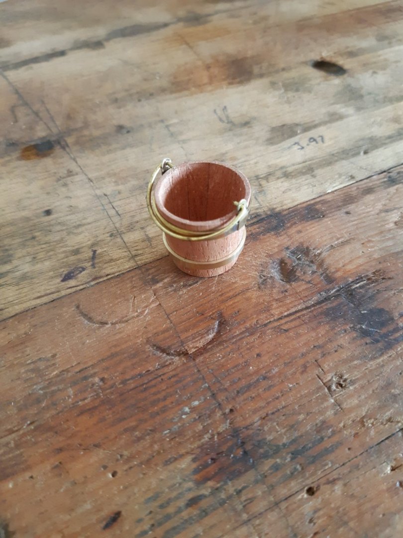
The bucket consists of 10 wedges of mahogany cut to an angle of 36 degrees and glued together on a 3mm MDF backing plate. I then used a 25mm holesaw to cut out the blank for the bucket, glued a dowel arbor into it to mount in a collet and drilled out the centre before running a 12mm end mill into it. Then with the compound slide set at 6 degrees ( scaled from a plastic bucket I have ) I cut the interior surface before cutting the exterior then I cut the bucket away. I used a plug cutter to cut a disc from some 0.8mm ply for the bottom and glued that in with a little CA from the underside. Next I mounted some brass stock in the lathe and repeated the process to achieve a hollow 6 degree cone in brass which I parted off to create the two bands. Solder a few tabs on, bend up a handle and there you have it.


- 30 replies
-
- 13
-
-
Spitfire MK I by Danstream - Tamiya - 1/48 - PLASTIC
Bedford replied to Danstream's topic in Completed non-ship models
That's a beautiful model, well done! I am always a bit confused about the use of mat colours on them though because I read in a book several years ago that the standing order was to "Polish them such that the regulation dry cheese cloth would slide off the wing" The aim was to give them the least possible drag. The fact that they were well polished would seem to imply a shiny finish wouldn't it? -
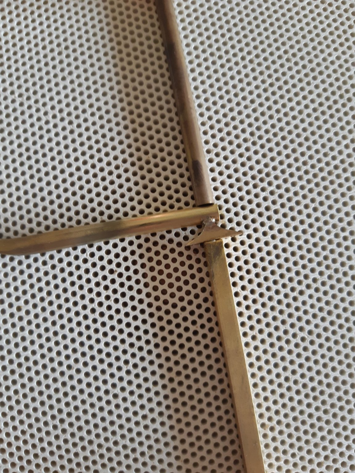
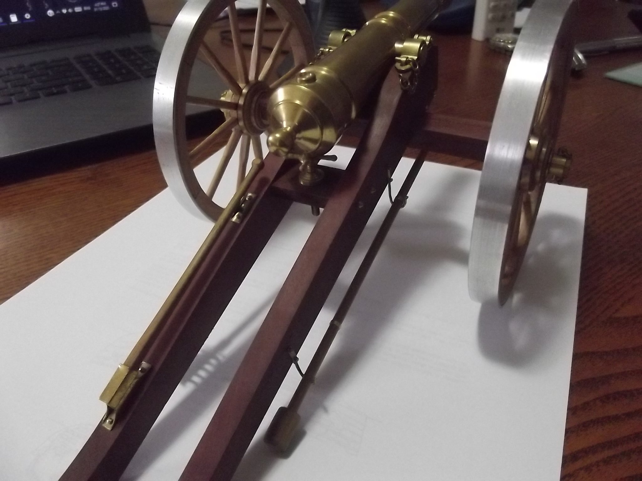
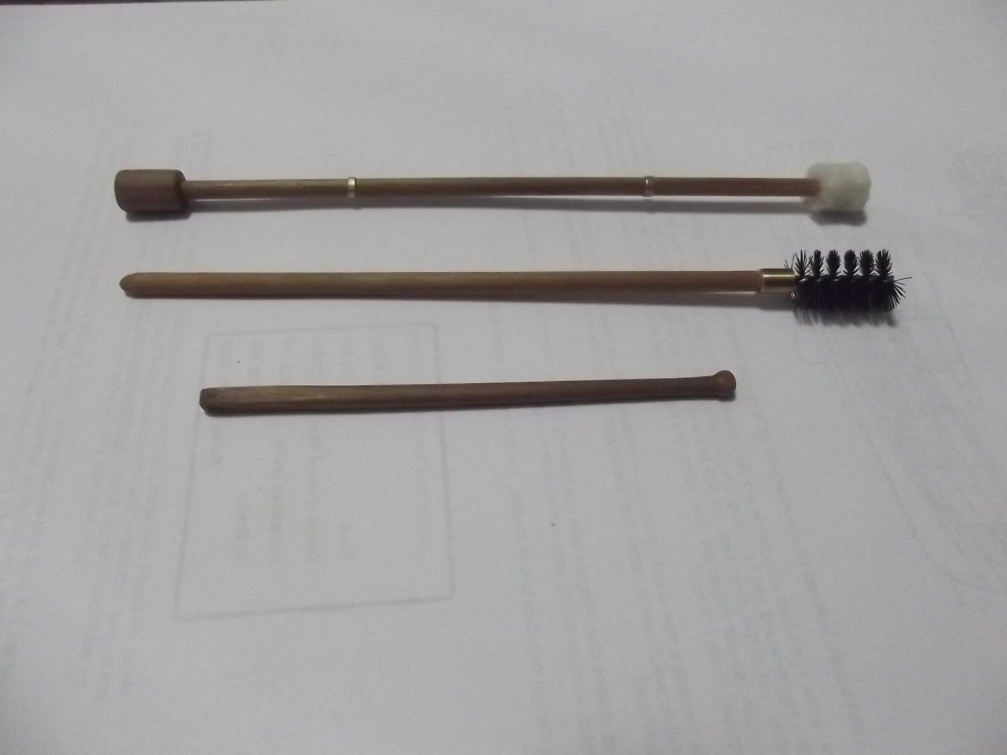
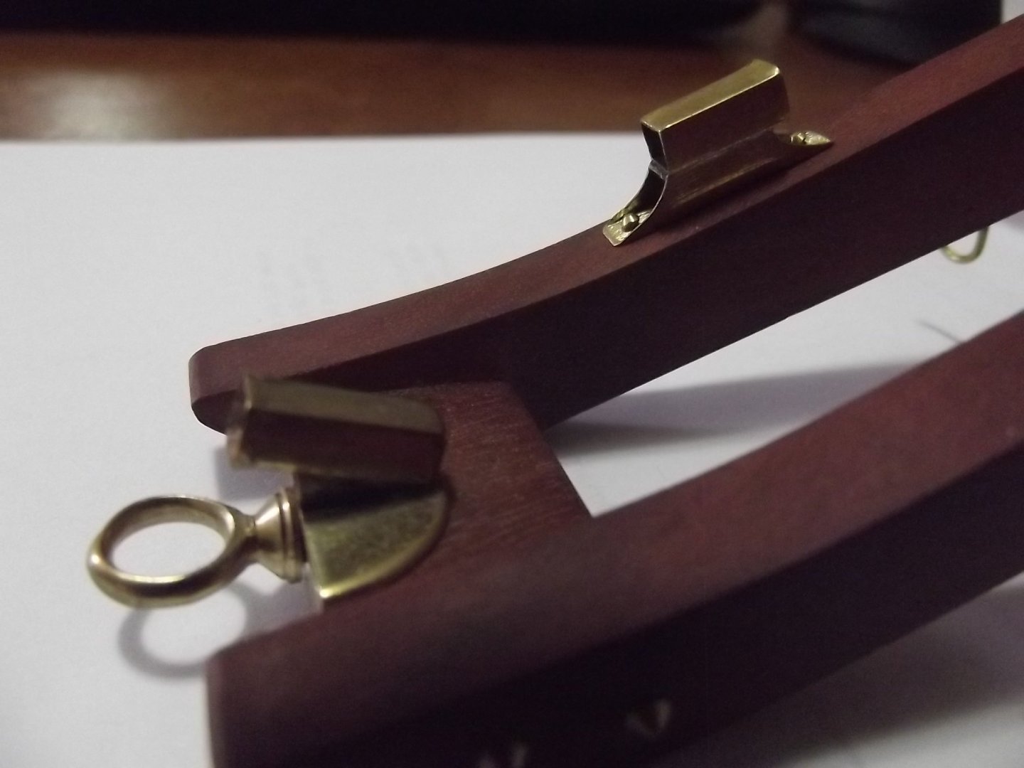
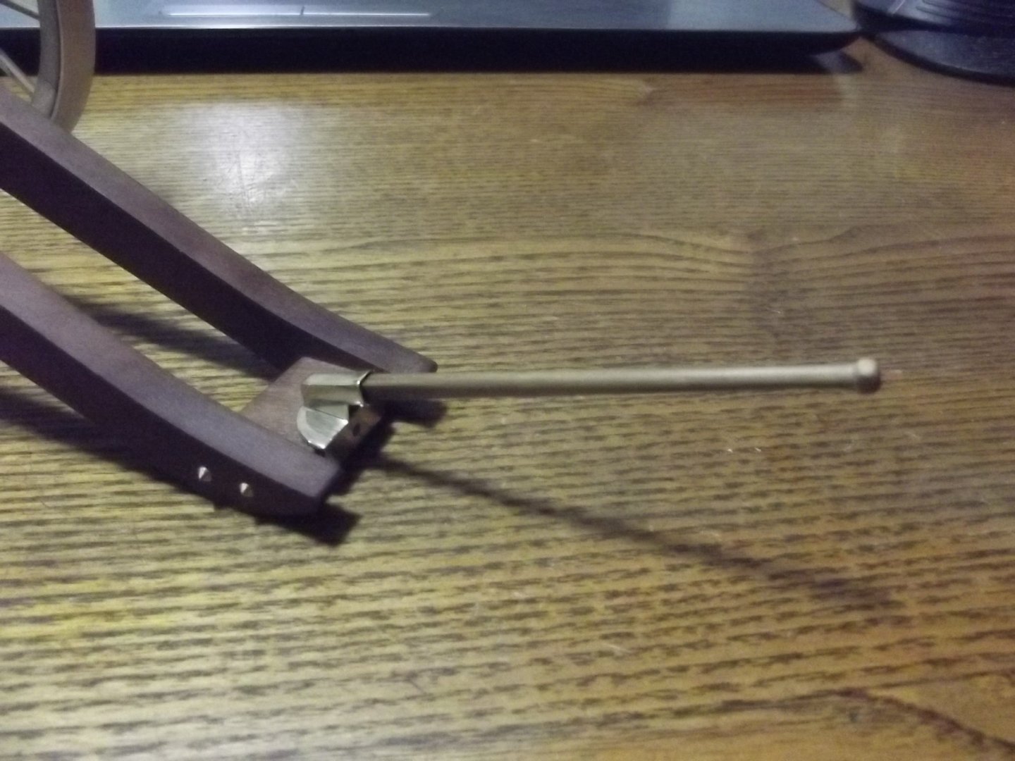
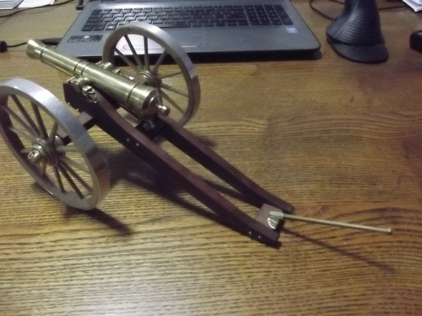
That left the holder for the maneuvering arm which is made of square brass tube ground to an internal radius at each end on a bench belt sander with another piece of the same tube slightly flared at one end soldered to the first and attached. The upper support is the same process but a section of round tube was soldered to the square base then worked to the open cradle shown. Next job...................................................a wooden bucket, I hope!


- 30 replies
-
- 14
-
-
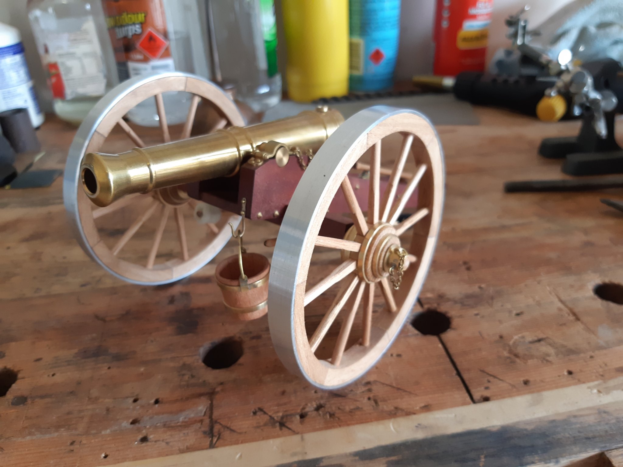
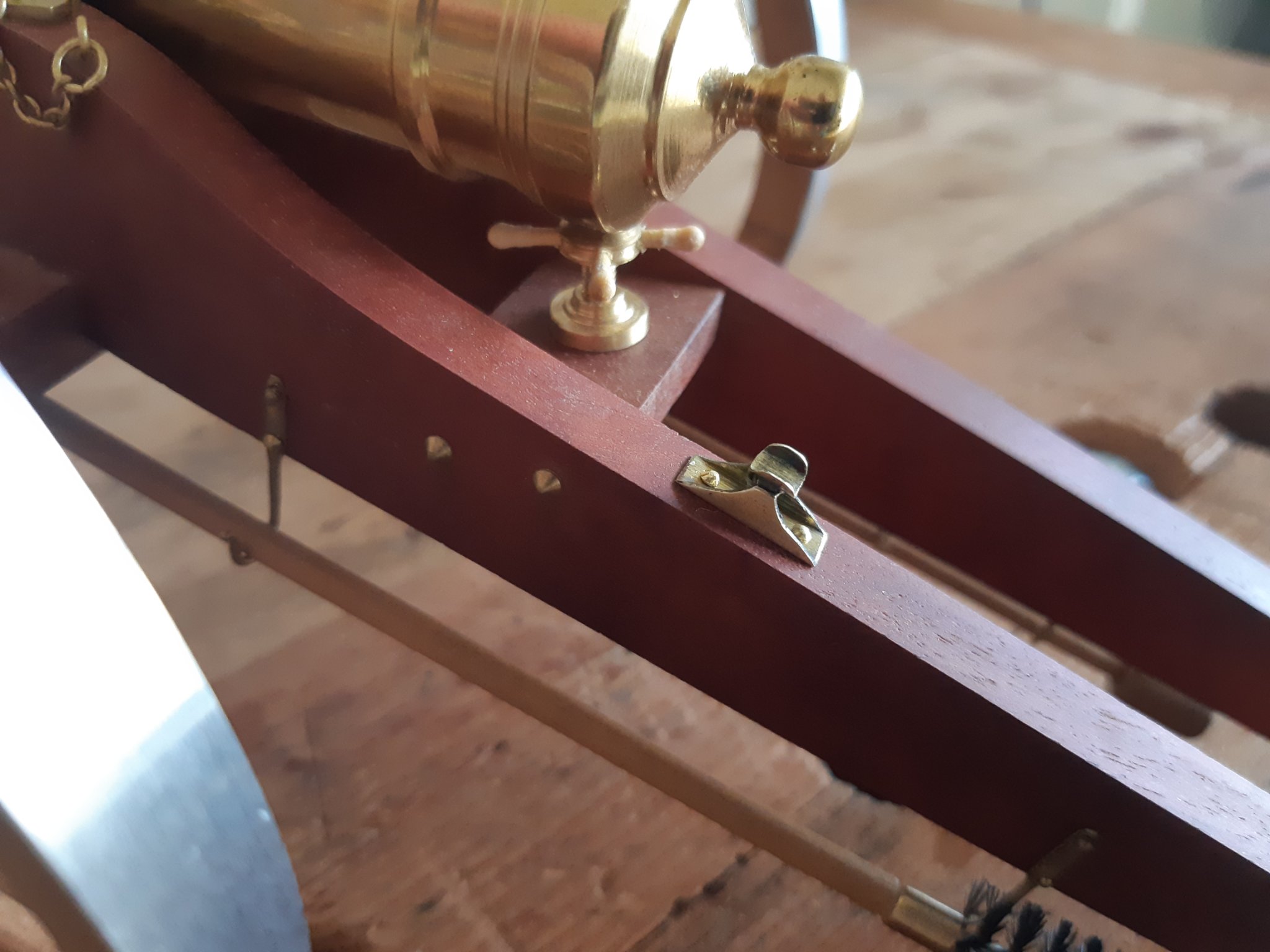
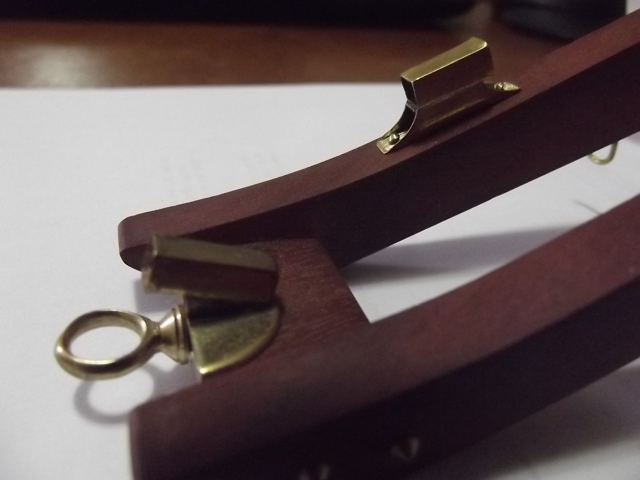
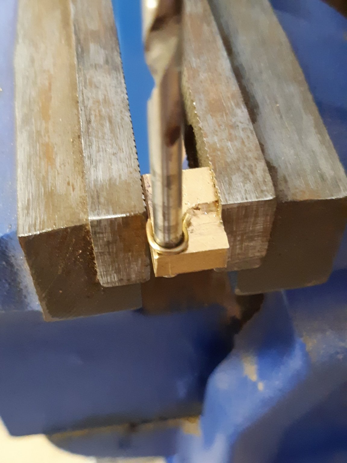
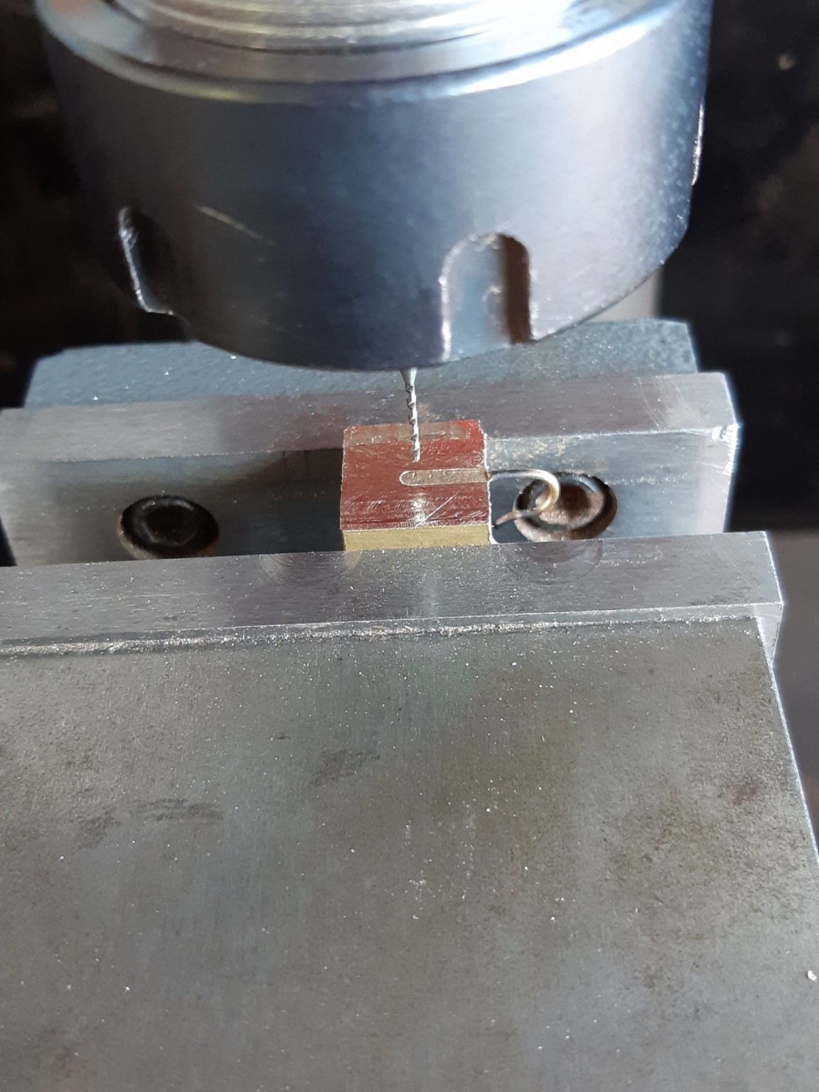
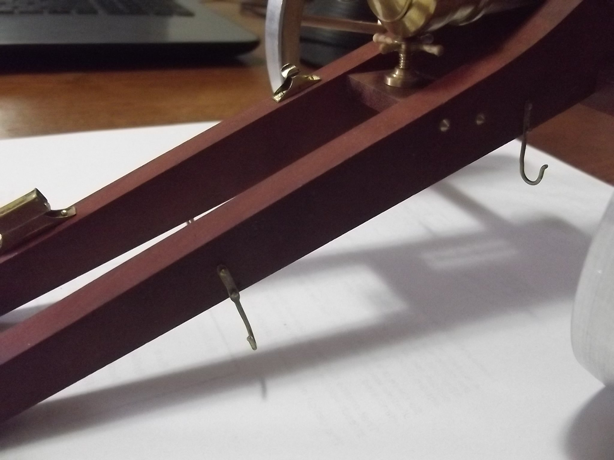
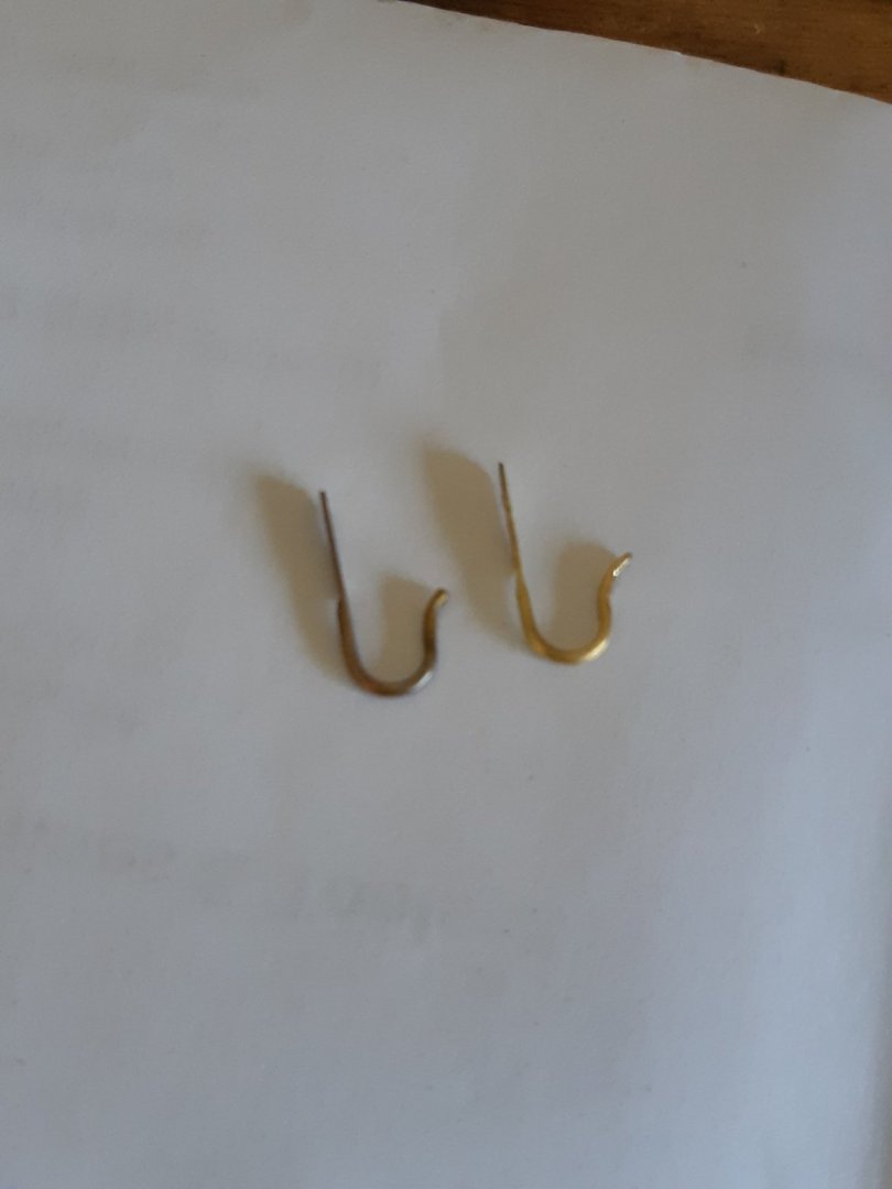
Once I had the accessories made I had to mount them so I hammered down some annealed 1mm brass wire to give a flat of 2mm width. Then milled a piece of scrap brass to make a former. The flat was clamped between the former and the vice, wrap the wire around a drill bit then work it into the curved rebate to give the "crook" shape. Then milled a 2mm wide slot into another brass off cut to hold the hook securely while drilling the holes.


-
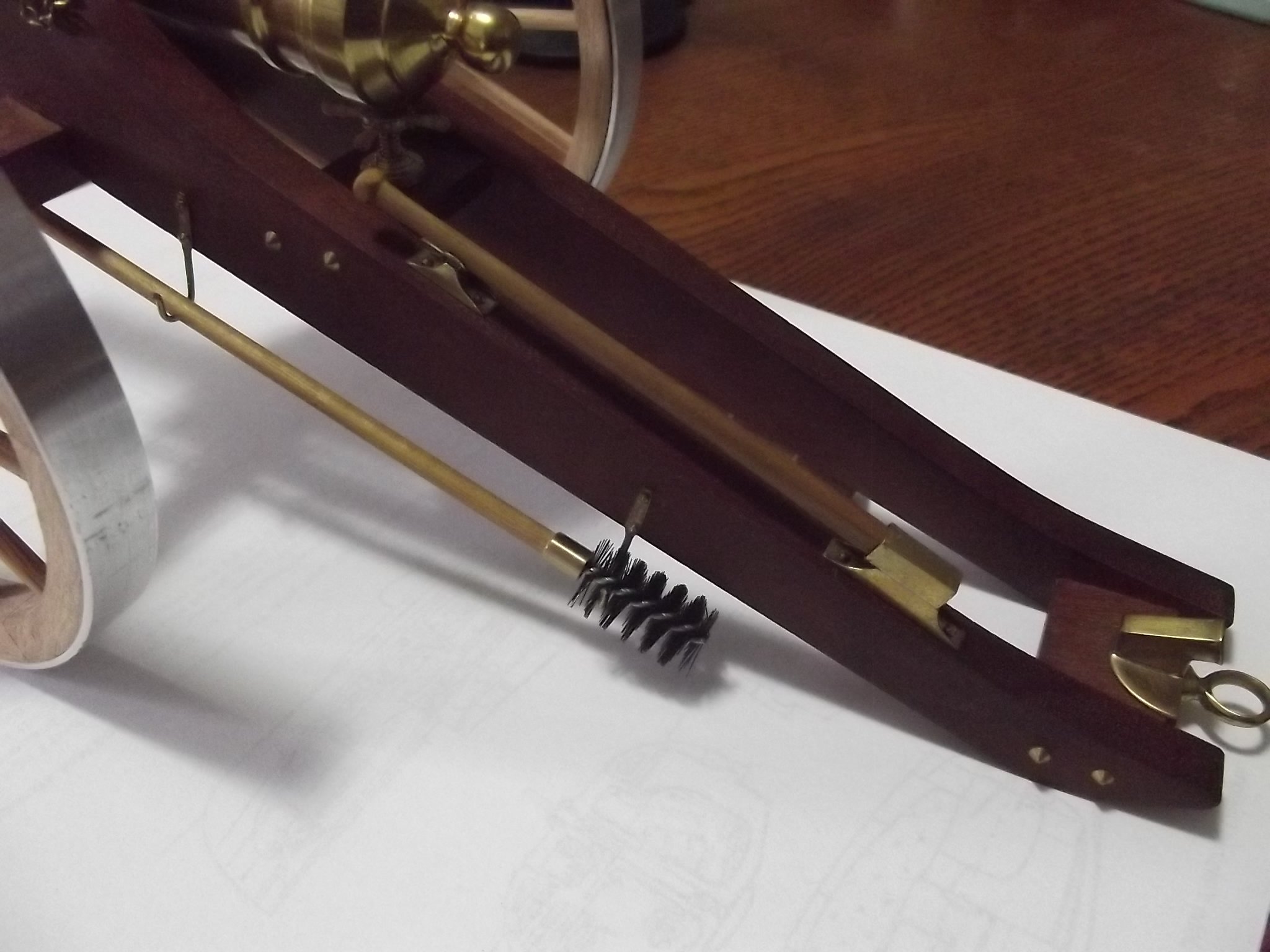
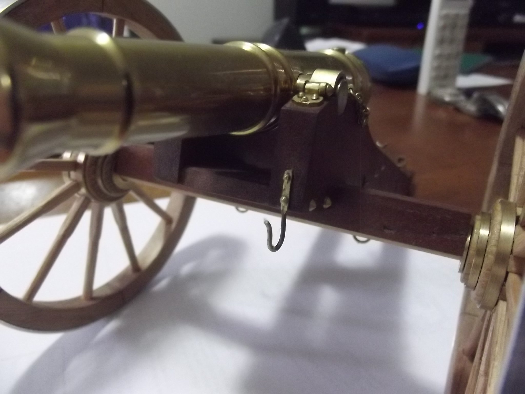
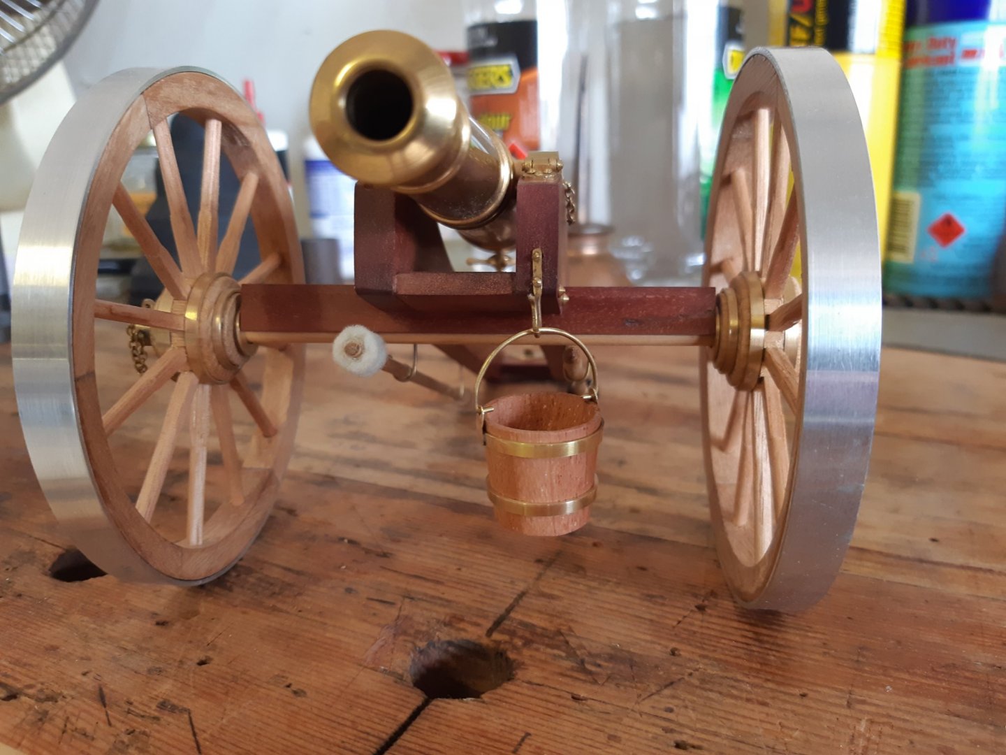
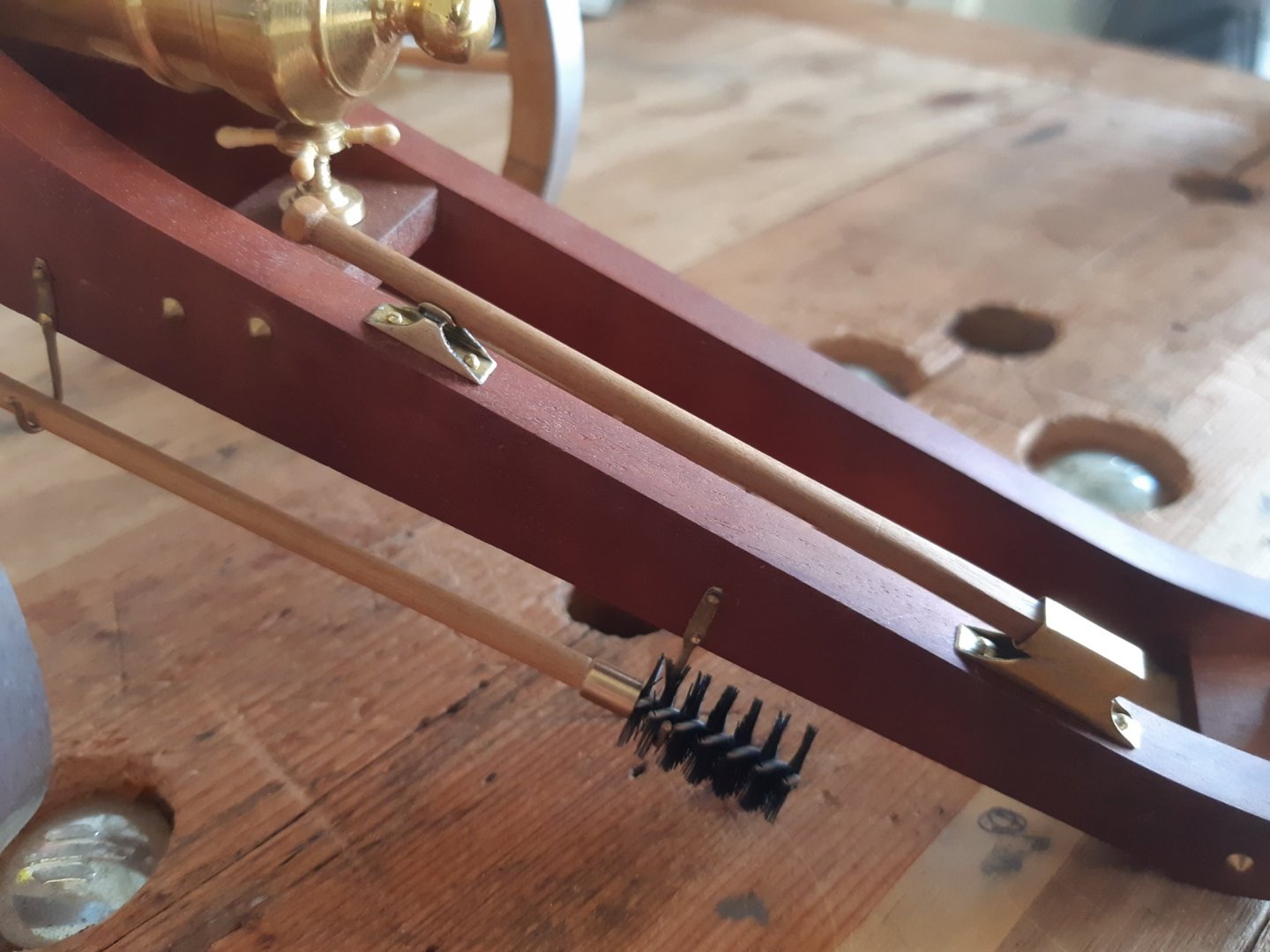
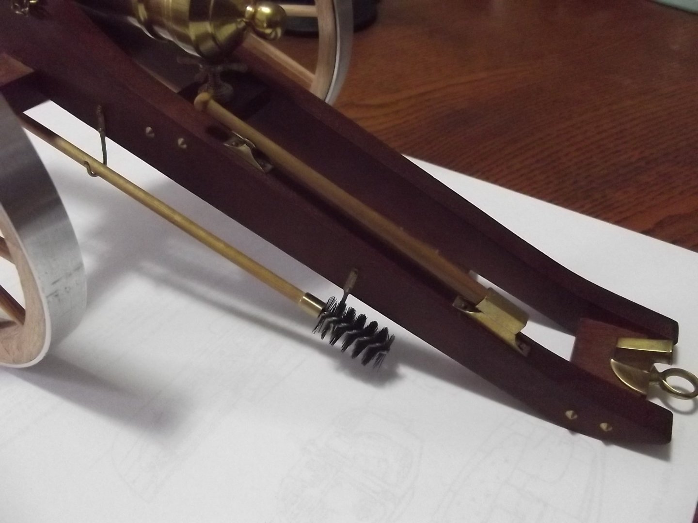
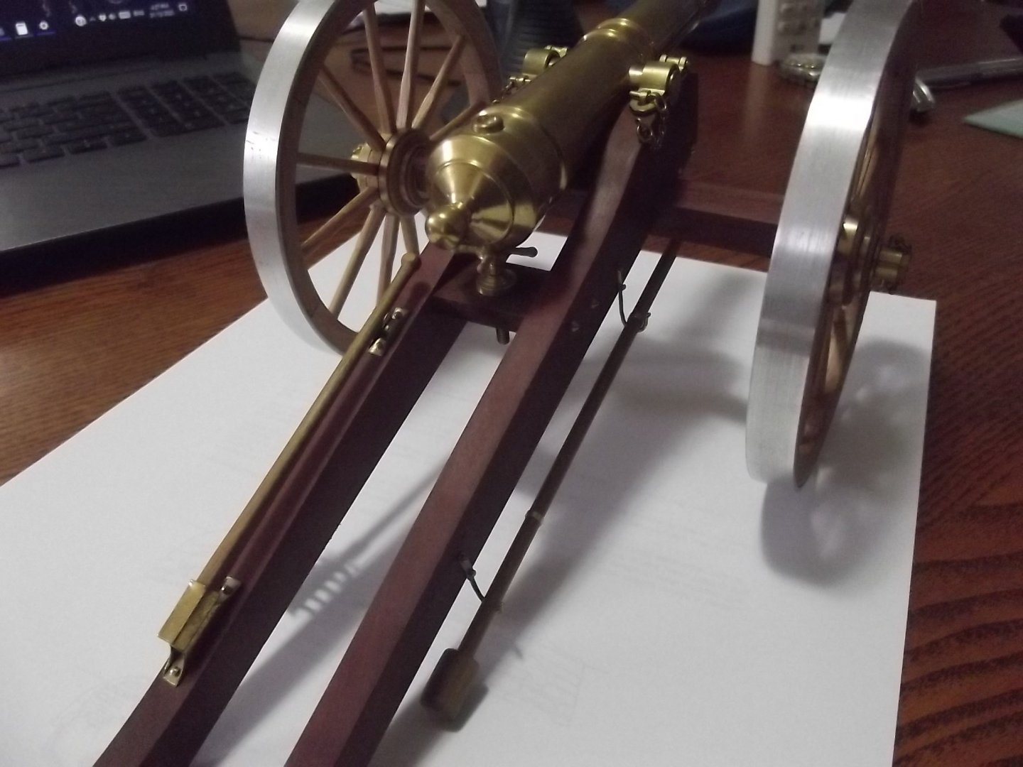
I've been a bit quiet on this one lately but here are a few more details taken care of. First, it must have a name but I don't know it so I'll call it a maneuvering arm which I guess would have been used to aim the gun and given my gun is designed to similar proportions and centre of gravity etc I can tell you there is very little effort required to lift and turn the gun using the arm. The brush, sponge and rammer are also made. The "sponge" is a small dremel polishing felt cut down a bit and the brush came in a set of pipe brushes of various sizes I got online and cut down to suit.

- 30 replies
-
- 11
-
-
I was wondering the same thing, it looks like it might be for winching a single line of very thick rope ?
-
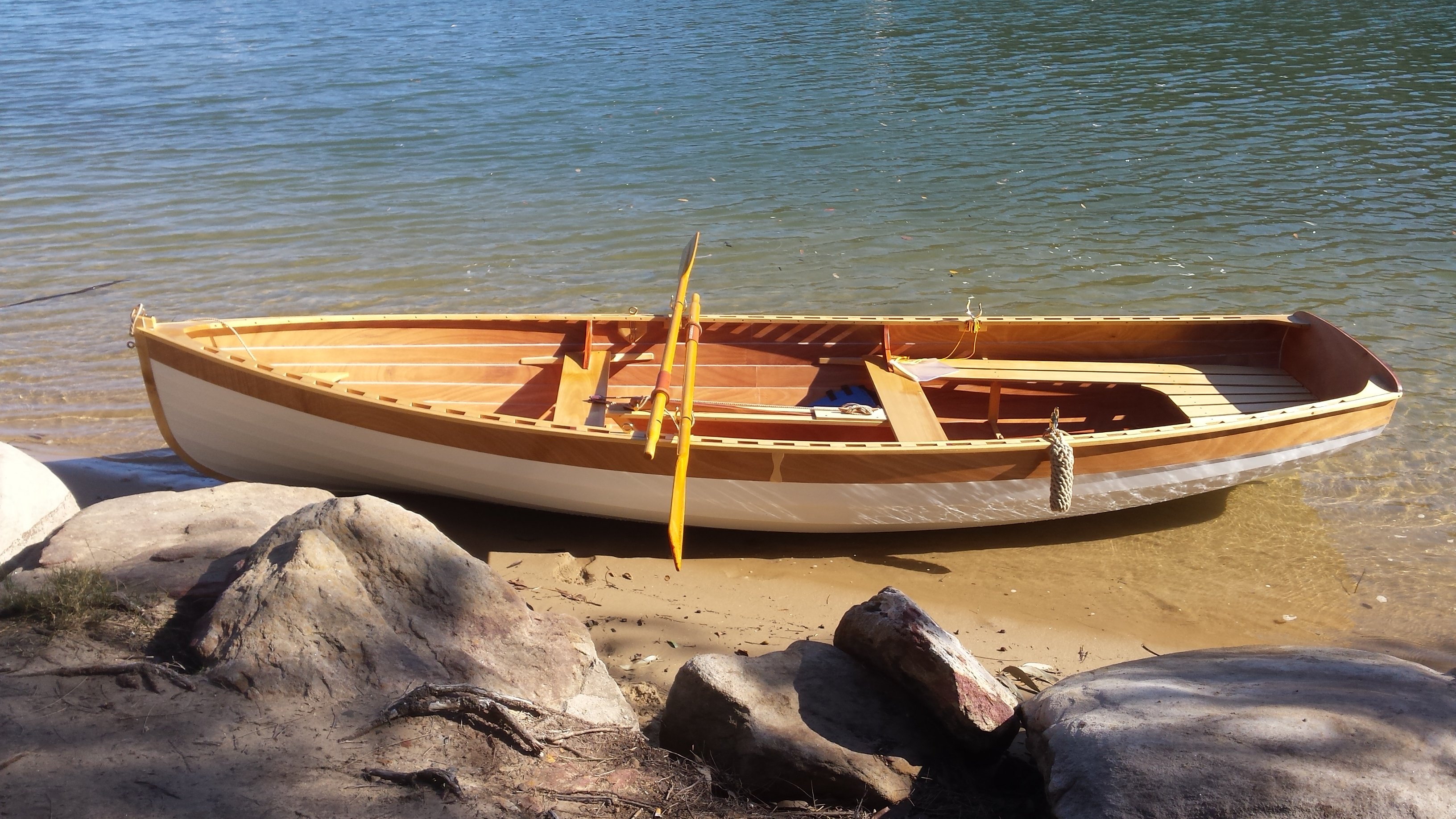
Chris that's really starting to look like a boat, good on you. The feeling you'll get as you first set out in her is something to look forward to.
-
Mate, I used to have a Defender, the floor was just above the door sills and it was designed to be hosed out, best way ever to clean out the floor of a car that gets muddy.