
MORE HANDBOOKS ARE ON THEIR WAY! We will let you know when they get here.
×


Bob Cleek
-
Posts
3,374 -
Joined
-
Last visited
Content Type
Profiles
Forums
Gallery
Events
Everything posted by Bob Cleek
-
Model Master Paints
Bob Cleek replied to rhephner's topic in Painting, finishing and weathering products and techniques
Do you mean this patch: Indeed, refer to my prior posts on using tubed artists' oils (or acrylics, if you wish) for model painting. Easily used and ounce for ounce, far, far less expensive. You don't have to store tons of bottles full of hardening expensive paint colors, either. -
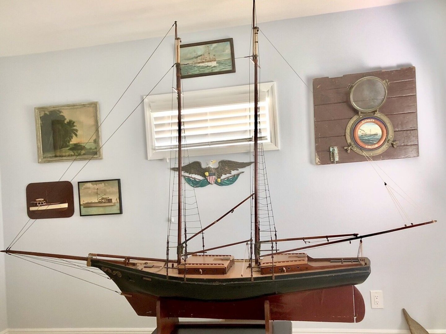
I never could figure out the topmasts on this model. There's just no explanation for going to the trouble of building all the top hamper necessary for fidded topmasts that are so short above the lower mast. You'd think a sane boatbuilder would have simply made the lower masts a bit longer and saved themself a lot of trouble. I wonder if somebody somewhere along the way decided to "bob" the topmasts in order to get them inside a room or something. Those topmasts sure do catch the eye. Stubby little things and who knows where the foresail gaff boom came from... or goes to? The spreaders, rather than trestle trees, seem somewhat incongruous, as do only two shrouds to a side per mast. It's true, though, that there are only two chainplates to a side per mast, which is a good indication of the original rig. From that, I'd guess it was originally a rather simple bald-headed working schooner rig. My inner detective causes me to suspect that this rig was rebuilt at some point prior to the latest restoration. Perhaps she was originally much more simply rigged as a pond model and later on somebody decided to turn her into a display model by giving her a much more extreme and complicated rig.
-
A lot depends upon the scale of the model and the details of the sternpost, gudgeons, pintles, rudder. Those variables are going to determine the best solution for fastening. I'm not sure what you mean by "there is usually little clearance between the two." There shouldn't be any clearance between a gudgeon and a pintle when the pintle is slid down into the gudgeon. Maybe a picture would be a big help. If the gudgeons are attached to the sternpost and the pintles to the rudder in the same manner as in full-size construction, the rudder should slide right down with the pintles sliding right into the gudgeons. The pintles should be sized to match the gudgeons. Sometimes it helps to file the tips of the pintles a bit round to get them sliding into the gudgeons easily. Like any hinge mounting, a good fit is going to demand that the positioning of the pintles and gudgeons are accurate. Alternately, you can always attach the gudgeons to the pintles and then mount the rudder to the rudderpost using the pintle tangs glued to the rudderpost (and preferably pinned to the rudder post, if your scale permits. Another approach is to "fake" the pintles and gudgeons mounted together on the rudder, wrap strips of paper where the gudgeon tangs should go on the rudderpost (or a bit of copper strip, depending on what suits the scale, then drill and glue pegs into the forward side of the gudgeons and drill holes through the tang on the rudder post and glue the rudder to the post with the pins in the holes. That will give you a rudder fixed to the rudder post with invisible pins or pegs which appears like the rudder is hung on the gudgeons. And again, you can dispense with the separate pintle and gudgeon entirely and just take a bit of dowel or rod the length of each pintle and gudgeon and score a line around its circumference at the middle. Attach your faux tangs for the pintles and gudgeons, glue the "pintle + gudgeon" pieces to the rudder, drill a hole through them into the rudder, glue a pin in that through into the rudder and then drill holes for the pins in the rudder post and glue the rudder in place. That should in smaller scales give you a neat appearing rudder attachment that is quite strong. Keep in mind that rudders are one of the more vulnerable parts of a model and are prone to getting whacked when the model is being worked on or moved. The stronger the attachment the better!
-
Cutty Sark main flag hoisting and rigging
Bob Cleek replied to Bruma's topic in Masting, rigging and sails
The "pole solution" is not impractical at all. It is the standard rigging method for any flag flown from a masthead for a very good reason: mast head flags are "set flying" on poles (properly called "pig sticks") because the pole raises the flag high enough to avoid its fouling on the mast and its attendant rigging. The above drawing correctly shows the house flag flown from a "pig stick" (staff) at the main masthead although the stick is much shorter than in actual practice and the hoisting attachment point is incorrect as described hereafter. The pig stick is rigged with a halyard (not shown in the drawing) fastened with a clove hitch to the middle of the pig stick with its fall extending down to the deck and then, in a continuous loop, the fall is again fastened to the bottom of the pig stick to serve as a downhaul in "messenger line" fashion. The halyard can be run through a block, as the drawing above would suggest, or through holes or over a sheave in the mast cap, as Underhill's drawing depicts. In this manner the stick can be two-blocked at the highest point on the mast, generally the truck, and held vertical by the downhaul (the looped halyard fall) at the bottom of the stick. The flag is often attached to the pigstick with separate rotating rings around the pig stick or by some other arrangement such as a secondary staff that rotates around the primary pig stick to permits the flag to rotate 360 degrees around the pigstick without wrapping on the stick. Note, however, that the above drawing incorrectly depicts the attachment of the foot of the flag's hoist as below the two-blocked halyard's attachment point on the stick. This arrangement would cause the flag to foul and chafe on the halyard block and wrap about the halyard block as the direction of its flying rotated. Properly, the foot of the flag's hoist is be fastened on the pig stick at a point above the halyard block and the truck, so that the flag flies in "free air" without fouling on anything. So, in a correct depiction, the pig stick would be significantly longer to permit the flag to fly free above the truck. Below: pig stick with wire secondary "staff" to permit flag to rotate without fouling (and exploded parts photo.) Below: pig sticks with wooden secondary "staffs" Pictures of pig sticks set aloft on a modern and a traditional masthead: -
Regarding downhill adventures, growing up in the 1950's in San Francisco was an adventure. The wheels were old "ball bearings" we'd get from the local auto repair garage or the wrecking yard, the axle was a whittled end of a two by four with nails driven into the end to spread it to a tight fit on the inside of the bearing. Brakes were the heels of your shoes. The teenagers in the photo had fancier brakes... hinged blocks of wood.
- 227 replies
-
- 12
-

-

-
What are ground toes?
Bob Cleek replied to allanyed's topic in Building, Framing, Planking and plating a ships hull and deck
Exactly. In fact, not even a "non-standard spelling," since there was no such thing as "standard spelling" back then! They just spelled phonetically and the word was "sounded out" by the reader. There were some efforts to standardize spelling prior to the 15th century, but standardized spelling didn't really start to catch on until the printing press became common. Manuscript writers continued with the phonetic spelling method for quite some time after. -
What Thukydides said. Very fine sandpaper. Use a hard sanding block so all you sand is the very edge itself. Pumice or rottenstone will restore whatever level of finish, matte to gloss, that you want, but it will take a lot of rubbing to remove a masking tape "lip." Better to start with sandpaper in the 400 grit range and go finer from there. The most effective way to avoid masking "lips" is to use a very thin masking tape (Tamiya or 3M Fineline) and apply your paint in multiple thin coats. When the paint is dry, carefully sand the edge down a bit before you remove the tape. It's never an exact science. Not infrequently, you'll tear up some paint along the edge when removing the tape, or discover a spot where the tape "bled under" the tape, and so on. In such cases, there's often nothing for it but to carefully remove the defect by sanding and do the darn thing over and over again until it comes out right. This is one of the jobs that makes having an airbrush really worth the cost.
-
What are ground toes?
Bob Cleek replied to allanyed's topic in Building, Framing, Planking and plating a ships hull and deck
"Tow" is "short and coarse fibers of little value separated from the longer and more valuable fibers through hackling in the manufacture of rope. Tow is occasionally used in the manufacture of inferior qualities of rope." (International Maritime Dictionary, rene de Kerchove, 2nd Edition, Van Nostrand and Reinhold Co. 1961, Litton Educational Publishing] "Tow" is also the short bits of fiber that break off of natural fiber rope, particularly hemp and sisal ("Manila") rope. On a large square-rigger, a lot of tow would find its way to the deck and collect in wet piles and muck things up. Hence the bosun's call, "Sweepers, man your brooms. Clean sweep down fore and aft." Another general meaning of "tow" is simply "worn out rope." "Tow" was sometimes collected and saved for use in canvas pockets for padding of various sorts in rigging and so on, and for caulking material when mixed with tar to make oakum. Worn out or rotten line was often recycled into oakum as well. Quality oakum, however, was made not from lengths of worn-out line or "tow," but from new, long hemp strands. The highest quality new hemp line or oakum is made from the strong fibers from center of the stalks of the cannabis plant, which are whitish in color. (Oakum used by plumbers to caulk iron pipe joints is usually made from tarred jute or burlap.) "Fibers and flyings" are what fill the air in a textile mill or rope walk and if you've ever been in a running textile mill, you will know that there is a huge cloud of fibers, little bits and pieces of broken fiber and dust, and "flyings" which are longer thin threads thrown off in the milling or spinning process, which must be continually cleaned up as they pose a large fire hazard. "Flyings" from the mills and ropewalks were used to make high quality oakum. Oakum is made by taking long fibers soaked in thick pine tar and simply twisting and rolling them into "ropes." The caulker has to prepare the oakum by unraveling lengths of the loosely twisted fiber from the loose ball (or "bale") of oakum and rolling the pine tar-soaked strands back and forth between the palm of his hand and the top of his thigh. (If you see a guy in the boatyard with his pants covered with tar on the front of his upper leg, he's a caulker! ) So, "The white ocham to be from flying & not from ground toes or decaid White ropes." means, "The white oakum specified here is to be made from mill flyings of the top-quality virgin white fiber of the plant and not from ground up tow or recycled rotten white hemp rope." Quality oakum will result in a longer-lasting caulking job. Using old, weak fiber from worn out, rotten, or "decaid" rope will rot and decay in short order. The Admiralty wanted to use "the good stuff" because they didn't want to have to recaulk in short order because the stuff used was rotten to begin with. Caulking mallet, caulking irons, and untarred "bale" of white hemp for making up oakum. See: Oakum - Wikipedia- 15 replies
-
- 13
-
-

-
I wouldn't bet on it not being noticeable, particularly when the rest of the furniture is installed. 34 inches is the rule of thumb because when a boat heels under sail, the sink has to be at least that height to be useable when the sink is on the leeward side. Many galleys have "butt belts" the user can employ to strap themselves in or even bars that drop in behind the user that can be used as a seat or to brace against in a seaway. A sink that much lower would be noticed by an experienced seaman. It might not be that big of a deal in an RV that sits level, but not in a boat that may be sailing on her ear half the time. Additionally, it looks like the sink is going to be below the waterline even at 34 inches and so it needs all the height it can get to make space for the sink drain elbow, hand pump, and the attendant plumbing with an anti-siphon loop and check valve. I wouldn't have bothered to comment on something I realize many would think was picky, but this model has been so perfectly done, I, for one at least, would hate to see a compromise like this one, even if you had to look inside to see it. That said, I trust Michael's impeccable judgment in the matter.
-
Farmed Douglas fir is far less suitable for boat and ship building than naturally-grown vertical-grained Doug fir with ring counts of twelve to eighteen rings per inch. Just about every wooden boat and ship built on the West Coast of the US up until recent times was built primarily, or exclusively, of vertical-grain Doug fir. This includes all the lumber schooners and the once-vast fleets of small fishing boats, including the Montereys, many of which are still going strong eight to a hundred years and more from their original launching. Vertical-grain Doug fir was long a favored species for laid plank vessel deckis. (Plain-sawn Doug fir is not nearly as good for home deck building because it does require painting to avoid weathering. Plain-sawn redwood was far better for home decking until it became cost-prohibitive.) In the Nineteenth Century, Doug fir (and larch in Europe) were favored for warship construction over teak, which became available to the Admiralty after Britain colonized India and Burma, because, although, bare teak stood up to the elements better than unpainted Doug Fir, teak was highly prone to splintering when hit by cannon shot and teak splinter wounds were highly likely to fester, unlike Doug fir splinters. Teak is also much more difficult to work than just about any of the usual ship-building woods, because its high silica content dulls tools very quickly. There was a time when prime old-growth teak was so available in Asia that teak cargo pallets and cargo hatch covers were made of it, but those days are long gone. The totalitarian governments in the teak growing nations clear cut the teak forests to provide export product to support their revolutionary governments and the elephants trained to extract teak logs from the forest without damaging them are no longer available, so large teak timbers necessary for vessel construction aren't available today in the quantities necessary. Having owned for over forty years a teak-planked yacht built to Lloyd's 100A1+ standards in 1963 by Cheoy Lee Shipyard, Kowloon, Hong Kong I can attest that the teak wood used to plank that boat is virtually unobtainable today. Having worked for a yacht brokerage specializing in classic wooden yachts in the 1970's and being intimately familiar with a broad range of wooden boat building quality, I experienced firsthand the phenomenon of teak's becoming the favored species for brightwork. Before the advent of fiberglass boats, a "gold plater's" brightwork would almost always be made of mahogany, preferably real Honduras mahogany, and well-varnished. Teak was favored only for decks because of its easy maintenance: saltwater rinse daily, or bleach and rinse as needed. (Originally, holystoning was a primarily a practice on naval vessels maintained "Bristol fashion" when abrasion of the deck surface was necessary because the tar used on the rigging above the deck dripped in hot tropical weather and was tracked by sailors' feet all over the teak decks. It became "traditional" in naval practice thereafter and is a very wasteful and "abusive" maintenance practice that wears down the decks and accelerates the need to replace decks.) As fiberglass boats were built in quantity on speculation and had to sit at the brokers' docks, sometimes for considerable time, until they were sold, varnished mahogany trim required regular maintenance of drying with a chamois and sanding and re-varnishing on a regular basis. The fiberglass boat manufacturers then began using bare teak for outboard trim on their vessels and marketed it as "highest quality." That's really how things like teak cap rails and grab rails became universal on fiberglass boats from the 'seventies on.
-
As a practical matter, there isn't any greater risk of wood warping due to humidity changes if left bare rather than being coated with any sort of moisture barrier. (The expansion of wood due to temperature changes is negligible, if not purely theoretical.) Wood expands and contracts as it absorbs or expels moisture. If the wood has been properly dried and stabilized before it is worked, and the model is kept indoors where the humidity is relatively stable (i.e. not in a bathroom used for long hot steamy showers,) it should be no more prone to warping than any other piece of wood in the building. "Sealing" wood is often misunderstood. There is no practical way to completely control the movement of wood as the ambient humidity fluctuates, but if its moisture content has stabilized when worked it won't move enough to notice or to damage the structure built with it. (Grown wood off the tree needs to be air-dried for a year per inch of thickness of the lumber, or kiln-dried to reach an acceptable moisture content for the species, before being worked.) Coatings can protect against a spilled drink or a wet sponging, but there isn't any way to completely prevent moisture from "doing its thing." Humidity, like the water it is, "will always seek its lowest level." (Pascal's Principle) All that coatings can do is slow that process and perhaps reduce the extent of absorption in fluctuating humidity cycles. Actually, few coatings, even epoxies, are truly moisture-impermeable. (Surprisingly, one of the more effective moisture barriers is good old shellac, a property which causes it to be used to insulate fine wire in electrical coils even today.) You don't want to store a ship model in a wet basement anyway. I don't believe there is any great advantage to putting any coating on a model built of a fine wood species that you want to present as bare wood. The natural appearance of the wood itself should be all that is required. On lesser grade wood species which will probably require staining in any event, however, a light coating of an oil, shellac, or matte coating is a good thing for appearances' sake if not overdone. It won't prevent the wood from moving with changes in humidity, though. Here again, it's a matter of taste. If you want the bare wood on your ship model to look like the real thing from a scale viewing distance, it should have a matte appearance. If you want it to look like fine hand-rubbed furniture, then, by all means, finish it like fine finished furniture. These are artistic decisions for each modeler to make as they find appropriate to each particular model. One thing to remember is that in model building, as with full-size wooden boat building, wooden parts move relative to their size and the direction of that movement is primarily across the grain, not with the grain. (This property in vertical grain planking is what makes carvel planking seams swell tightly and become watertight and plain sawn planking swell against the adjacent lapping plank in lapstrake planking.) It's the soft wood between the harder "rings" that absorbs the most moisture and swells the most. Very few wood species swell much at all in length. The larger a piece of wood is, the more it will swell and shrink. Models, being made of a lot of very small pieces of wood, aren't prone to moving much at all, but improper grain orientation, particularly in large parts in the structure, can cause structural problems at times if humidity extremes are encountered. I suppose it's a matter of taste, but I favor leaving wood that I want to portray bare wood (e.g. decks) to remain bare, or at least appear so, given the frequent need for staining and weathering. At most, I give bare wood a single coat of thin white shellac for protection from staining from handling and ease of future cleaning. I suppose we have the Admiralty to thank for the fashion of bright (unpainted) wood in ship model kit hulls these days, but, aside from displaying the intricate framing and planking of a fully-framed Navy Board style hull, I don't see a lot of point to leaving hulls bare, or even building them "plank on frame" or "plank on bulkhead at all. (It's my guess the kit manufacturers favor planking because they can pack the kit in smaller and lighter boxes that way.) A "bread and butter" hull glued up of "lifts" or even a carved solid hull, is a lot faster and easier to build than hanging plank if you're not going to show bare wood. But I suppose that's a story for another night.
-
Tinting shellac?
Bob Cleek replied to CPDDET's topic in Painting, finishing and weathering products and techniques
All you really need to know about shellac is that it is an organic resinous material that dries hard and is soluble in alcohol. It comes in a range of shades from clear ("white shellac,") which is bleached, and shades of orange through dark brown. It is most easily bought premixed in pint or quart cans. It can be thinned as needed. Mixed shellac is designated by the "cut" expressed in pounds, that being one pound of shellac flakes to one gallon of alcohol is a '"one pound cut." It's safe and easy to use. Out of the can, it is the consistency of water and will soak into bare wood as water would and dry with a flat finish. Additional coats will build in thickness and yield a glossy finish which can be hand-rubbed down with fine sandpaper, steel wool, or a Scotch-brite pad to knock the gloss off. Any alcohol-soluble dye, stain, or coloring can be added to shellac. Given that alcohol mixes well with water, I'd expect even water colors might work to color the alcohol. To give you an idea of how shellac behaves with coloring additives, India ink is simply thin shellac with lamp black or some other black pigment added. If I were you, I'd experiment before putting colored shellac on a finished model, of course, but I'd also consider applying a stain or dye to the bare wood first and then to apply clear shellac over it, rather than trying to get the color into the shellac first. -
What is it that you wish to accomplish by applying a finish to your pear wood? Preventing it's darkening will pose insurmountable challenges. Applying oil will darken most woods to one degree or another upon application, of course. (It's not a matter of applying the oil thinly with a rag. The oil soaks into the wood, rather than staying on the surface.) Regardless of what you might put on it, all wood will darken over time from the polymerization of polyphenols from lignin into tannins which are dark red or brown in color when they are highly polymerized. The specific content of the lignin in different woods affect the density, strength and color of the wood. Cherry wood, for example, may darken so quickly that care has to be taken in large jobs to keep the stock covered to prevent uneven darkening before the job is finished so the color tone will match across the entire job. Osage orange wood goes from bright yellow to dark brown. Pear also darkens noticeably. This darkening is favored in some woods which become more beautiful as they age, Honduras mahogany, cherry, and walnut, for example. Indeed, stains and dyes are used primarily to mimic the appearance of fine aged woods, which they accomplish well in the short term to the unpracticed eye, but destroy the potential of the later greater beauty of naturally aged wood pieces. Such finishes will also accentuate the figuring in some woods, of course, but that's the last thing desired in a scale model. This natural darkening process is primarily a function of exposure to UV radiation and oxygen. The darkening effects of oxygen can be reduced, but not totally eliminated, by applying some sort of barrier coat fully encapsulating the wood, clear shellac being one of the most effective which is otherwise invisible when thinly applied, but the problem is that the majority of the natural darkening is the result of sunlight, rather than oxygen, so clear shellac is only of limited effectiveness. If you keep your model in a darkened environment, as seen in many museums for conservation purposes, you can slow the visible effects of the wood's aging from UV exposure. Otherwise, one would have to opt for a marine spar varnish with UV inhibiting additives, which are themselves only partially effective. However, the effectiveness of varnish with UV inhibitors increases with the thickness of the coating (eight coats being the industry standard) and, obviously, thick coats of varnish aren't what anyone would desire on a model where the thickness of the coating would destroy sharp detail. Spar varnish is also a glossy finish, so it would have to be hand-rubbed to a matte finish on a model, have a flattening agent added to it, or be top-coated with a clear matte finish. (I know of no "satin" varnish marketed which contains UV inhibitors.) Bottom line, preventing the natural darkening of the pear wood in your model over time really isn't possible. If you feel it is necessary to seal the bare wood for some reason, maybe out of concern from accidental staining or to make cleaning easier (although a good case is a better investment in that respect,) a very thin coating of shellac or clear lacquer preferably sprayed on (to minimize the thickness of the coating film) is the alternative. While I realize others' mileage may vary, I would not advise the use of "rattle can" aerosol spray coatings for fine modeling work. Canned spray paint always poses the risk of a "nozzle spit" ruining the job, the plastic nozzles don't permit adjusting the shape of the spray or the amount of coating material applied, often resulting in thicker coating in corners and thinner on edges, and the color selection is limited to what's on the shelf. Canned spray paint is also extremely expensive. A good brush and properly conditioned paint applied in multiple thin coats is, in my opinion, a far better option if you don't have an airbrush. While an airbrush requires a bit of a learning curve, its use isn't daunting. I realize the expense of buying an airbrushing rig may seem beyond the budget of some, but the flexibility, results, and time savings an airbrush provides is not an unreasonable investment in one's modeling hobby and an expensive top of the line airbrush, while nice to have, isn't an essential requirement for basic modeling work. If you invest in an airbrush, I think you'll find painting a model with a "rattle can" was a lot like driving a tack with a sledge hammer.
-
Ditto. Very true. And both stain and dye will soak into end grain at a far greater rate than side grain. India ink (essentially thinned shellac and lamp black) will work well to mimic ebony on close grained hard woods, though.
-
Elementary school clear glue?
Bob Cleek replied to modeller_masa's topic in Modeling tools and Workshop Equipment
Absolutely! I'm a Californian and I can attest that getting "banned' materials here is something of an art form. Fortunately, Nevada, a decidedly environmentally unfriendly jurisdiction is just across the border about 200 miles away. -
Ditto! Lovely as they are, we really have more than enough models of warships from the Age of Sail. For too long, modelers, and kit designers, have overlooked the rich history of and abundant information about inshore working craft as modeling subjects. I should think such boats would be a rich vein to mine for a model kit designer because they are of a size which permits the portrayal of rich detail at large scale while, at the same time, producing a model small enough to display in a home smaller than an English manor house. I anticipate this will be a valuable building log.
- 16 replies
-
- 10
-
-
- Sophia Rose
- Block Island cowhorn
- (and 1 more)
-
Elementary school clear glue?
Bob Cleek replied to modeller_masa's topic in Modeling tools and Workshop Equipment
The material safety data sheet ("MSDS") is the first stop in checking out any material. This stuff is safe for kids to eat. Some of us learned this firsthand in kindergarten with the paste version. See: https://s3-ap-southeast-2.amazonaws.com/wc-prod-pim/Asset_Documents/Elmer's Clear Glue SDS.pdf I learned in early childhood that whatever made my mother yell, "That could put your eye out!" was probably was the most fun. I've always applied a corollary to this principle to materials in my workshop: if somebody says the material is hazardous or environmentally unfriendly, I assume it is the better choice for the job than the "safe and sane," "environmentally friendly," or "green" options that have been "dumbed down" for use by people who can't be trusted not to eat or drink the stuff. .- 10 replies
-
- 10
-
-
-
I've had similar success with Duco Cement. It's just a very basic nitrocellulose adhesive. The nitrocellulose is dissolved in acetone which evaporates quickly upon exposure to the air. See: 14445 TN.pdf (tedpella.com) and ANSIMSDS.RDL (onboces.org) The dried cement is primarily nitrocellulose, which is also known as "gun cotton." It can be highly flammable when exposed to enough heat. Duco Cement is sold in one ounce tubes for as much as ten or twelve bucks an ounce. On the other hand, ordinary PVC pipe cement, which is quite similar to Duco Cement, can be purchased in four ounce cans for as little a dollar an ounce, or one tenth the price of Duco Cement, so one may wish to experiment with plastic pipe cement and see how they like it. Another similar option is "sprue goo." Some plastic modelers use "sprue goo" as a plastic adhesive and filler material. "Sprue goo" is simply cut up pieces of plastic model sprues dissolved in acetone or a similar solvent. There are a number of how to make it online.
-
Where one requires strength, archival permanence, or both, I think that it is important to mechanically fasten model parts wherever possible. Sometimes such fasteners can be simple wooden pegs in the case of wood-to-wood bonds, and other times a metal peg is called for when a metal-to-wood bond is required. Metal-to-metal bonds generally require soldering. It should also be remembered that a part simply glued to any painted surface is bonded no more strongly than the strength of the paint film between the parts and that a paint film is generally not considered a particularly strong bond, especially when under sheer loading. (In other words, little parts glued to painted surfaces get knocked off very easily.)
-
No chimneys on my 9" Tung Woo running lights. I've never seen interior chimneys on ships' lanterns. They certainly make sense in the larger sizes. Nice polishing job! Maybe I'll tackle polishing mine.
-
Are you sure that water isn't coming in through your propeller shaft bearing?
-
The good news is that nobody knows what Columbus' ships looked like exactly. All we know is that they were a "type" of vessel and precious little is known of what those "types" actually looked like in any great detail. Your kit is only the kit designer's approximation of what he thinks it might have looked like, so you are free to do a bit of creative "approximating" yourself. If you wish, you can take a couple of thin rectangular strips of wood (about the thickness of a deck plank) and of a size suitable to cover the holes of the oversized eyebolts Mamoli provided and glue those over the "damage." You can make them so they fit right up against the side of the rail and transom and perhaps have rounded corners on the inboard corners. That will look like a "pad" commonly placed on decks to reinforce things like eyebolts (which may well have never been in use on any of Columbus' ships in the first place.) They will also give you more "meat" to drill into and glue your much smaller and correctly-scaled eyebolts. Your smaller eyebolts can easily be made by twisting some fine copper or brass wire around the shank of a suitably size drill bit. The twisted end will enable the glue to hold much better, too. When judging the scale of fittings, it's always helpful to use a "manikin" to judge size. It doesn't have to be fancy. At the most basic, just take the scale of the model and then draw a scale stick figure on a piece of card stock and glue it to a little block of wood so it stands up. Figure about five scale feet tall or a smidgen more. (People were smaller in those days.) You can then place your "little man" near where you are working and get an idea of whether the parts you are making "look right." Of course, a pair of calipers and a good rule will serve as well, but when estimating, I find the manikin is a helpful tool. If you do this, I expect you will see that the kit eyebolts are about the size of small automobile tires! When you drill your holes for the new eyebolts, take care to be sure your bolts are placed exactly as indicated on the plans. Don't trust yourself to "eyeball" placement. Measure and be exact. It may be helpful to make a small pattern out of paper or card stock and draw a straight line where you want your eyebolt holes and then mark equally spaced points on that line. You can then put the pattern over the deck where you want the eyebolts and mark the points where you want to drill by pushing a map pin or awl into the wood to make an indentation to start your drill bit. On your first effort, the eyebolts ended up here, there, and everywhere. You don't want to repeat that on the second try.
-
Just a mention in passing: ModelExpo doesn't appear to sell stud-link anchor chain at all. They only sell scale common chain. Following its invention and British patenting in 1819 stud-link chain quickly replaced common chain for anchoring chain in vessels over about 75 feet long or so. It was stronger than common chain of the same size, was less prone to jamming or jumping a wildcat, and stowed without "clumping" or kinking, always running free when the anchor was dropped. I would expect stud-link chain to be used by any of the American (including Canadian) fishing schooners. BBC - A History of the World - Object : Ships anchor cable chain link with stud. Most all of this stud-link anchor chain was initially and for a long time thereafter manufactured by Brown Lenox in England (suppliers to the Admiralty,) and, presumably, exported to North America. Since 1960, at least, Lister Chain and Forge in Blaine, WA has been supplying it to the United States Navy and civilian market. Scale stud-link chain used to be near-unobtainable and had to be fabricated by the modeler. Jewelry wholesalers offer stud-link chain in smaller sizes, known to that trade as "marine chain," but this is generally made of precious metals and cost-prohibitive for modeling purposes. About ten years ago, Mathews Model Marine was offering 3D-printed plastic stud-link chain in a range of sizes designed for 1:200 scale naval vessel models (which requires delicate hand-working to clean and separate the links,) but I don't know if this is still available. See: Ship review (modelwarships.com) Fortunately, Caldercraft and a couple of others presently offer brass stud-link chain in a wider variety of sizes on eBay. See: stud-link anchor chain for sale | eBay For the more adventurous types, there's an excellent instructional piece on crafting stud-link chain from scratch in this forum's Articles Database: HowToMakeStudLinkChain.pdf (thenrg.org)
-
The wood decomposed in the dirt and left the earth a darker color where the wood had been. They excavated carefully until they reached the dark dirt and knew that was where the ship had been and were from that able to recreate the lines of the ship. You can see the darkened earth defining the shape of the ship in the photo Louie posted above.
-
There are many books on rigging and some are even reprints of contemporary instruction manuals. The Articles Database in this forum contains two contemporary rigging manuals. Nautical Research Guild - Articles and How Tos (thenrg.org) You may also wish to obtain a copy of John Leather's Gaff Rig, (Gaff Rig: Leather, John: 9780877420231: Amazon.com: Books) or The Gaff Rig Handbook (The Gaff Rig Handbook: John Leather: 9781408114407: Amazon.com: Books) which treat the gaff rigged schooner in detail. Lennarth Petersen's Rigging Period Fore-and-Aft Craft and Rigging Period Ship Models, while not without some shortcomings, are good basic treatments of the subject. Rigging Period Fore-and-Aft Craft by Lennarth Petersson | Goodreads As for the "classics," every ship modeler's library should have copies of Charles Davis' Ship Models and How to Build Them (Ship Models: How to Build Them: Davis, Charles G.: 9798395212047: Amazon.com: Books) and The Built-up Ship Model (The Built-Up Ship Model (Dover Woodworking): Davis, Charles G.: 9780486261744: Amazon.com: Books). Another "classic" author is Harold Underhill. His basic modeling manuals, although, like Davis', somewhat dated today, are invaluable primers that do not presume the modeler requires thousands of dollars invested in expensive power tools. Grab copies of Underhill's Plank on Frame Models and Scale Masting and Rigging, Volumes I and II. There are lots of these available on the used market. Gerald Wingrove's Techniques of Ship Modeling is a great how-to-do-it book and widely available on eBay and other used book selling sites. The Techniques of Ship Modelling: Wingrove, Gerald A: 9780852423660: Amazon.com: Books Last, but not least, The NRG's Ship Modeler's Shop Notes, Volumes I and II are treasure troves of "tricks of the trade" and reference works you'll find yourself going back to time and again. (Available used from "the usual suspects" online and new from the NRG Store at this website. Of course, you'll find many valuable bits and pieces of information in the many build logs here, as well. The above books are just some that I think you would find useful as a new ship modeler starting off with the build you've chosen. There is a wealth of other more specialized books (often at much greater prices) that you will probably find yourself lusting after once you've collected the ones mentioned above. One thing that those new to ship modeling often overlook is that research is as much a part of the hobby as anything else. Kit manufacturers often attempt to provide a detour around this "speed bump on the learning curve" by providing parts, plans, and insructions of varying degrees of quality, but taking that route often costs in terms of the ease, enjoyment, and quality of the build. You won't find a serious ship modeler anywhere who doesn't have a research library of some kind and you won't find a scratch modeler anywhere who doesn't' have a substantial one. Good books are a decent investment. As with anything else, there is a fair number of mediocre books out there, but the classics are easily identified and often available on the online used book market at rather reasonable prices. A nice library is not a difficult thing to acquire if one budgets for it and keeps a sharp eye out for used book bargains. A budget of twenty-five to fifty bucks a month, more than some spend at their neighborhood bar in a week, applied judiciously to acquiring good modeling books, will build a good library in no time.
