HOLIDAY DONATION DRIVE - SUPPORT MSW - DO YOUR PART TO KEEP THIS GREAT FORUM GOING! (Only 36 donations so far out of 49,000 members - C'mon guys!)
×


Glenn-UK
-
Posts
3,156 -
Joined
-
Last visited
Content Type
Profiles
Forums
Gallery
Events
Everything posted by Glenn-UK
-
 I have added you build link to my build log index on my build log. Looking forward to watching your build progress.
-
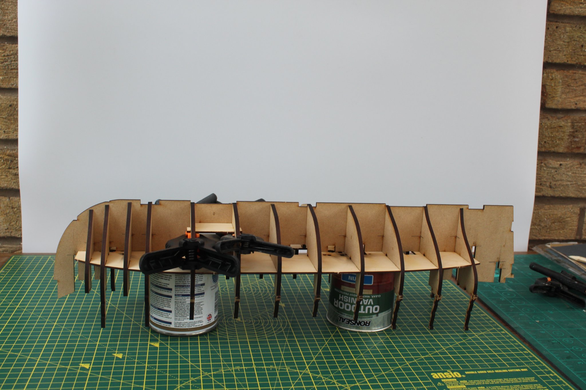
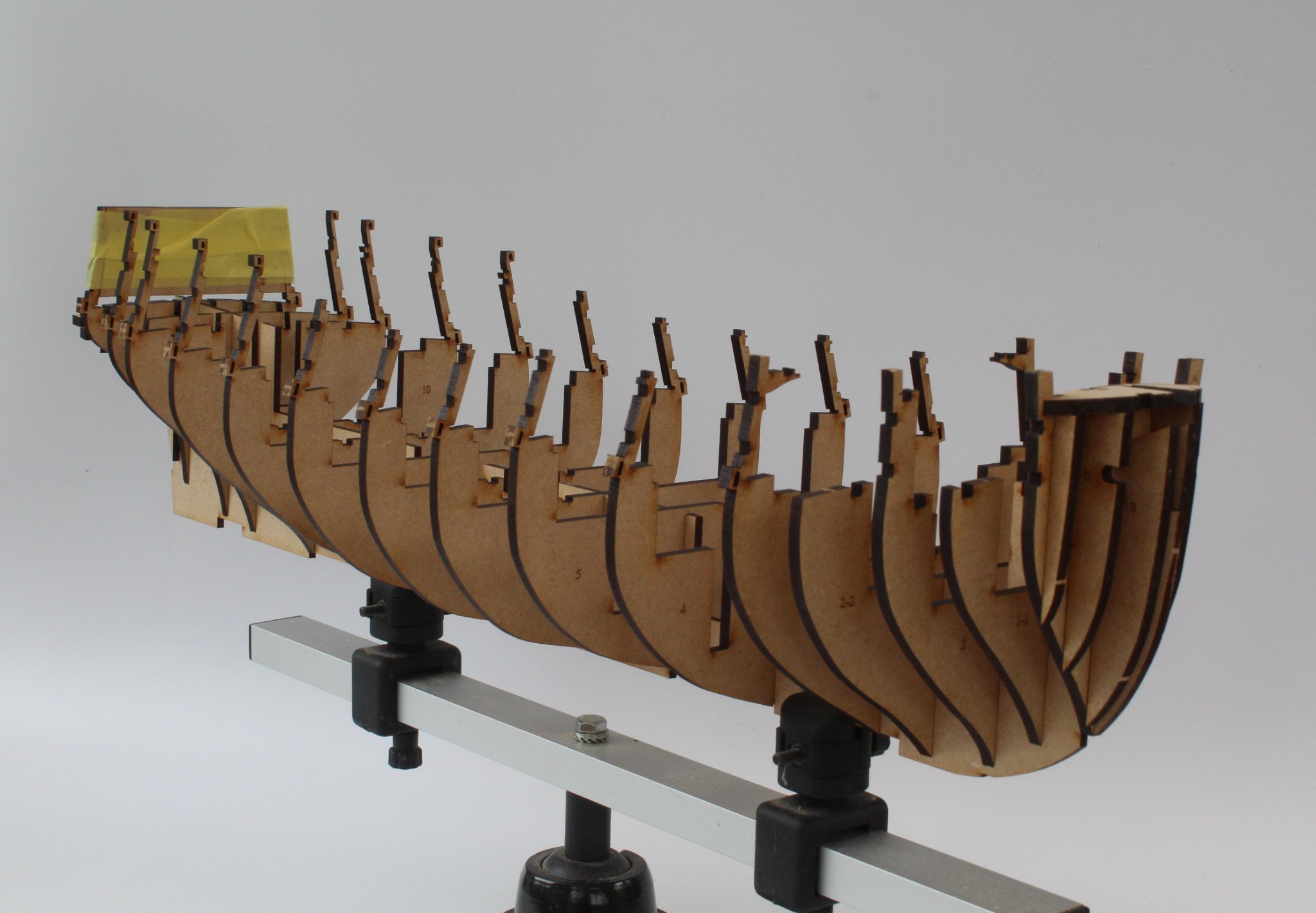
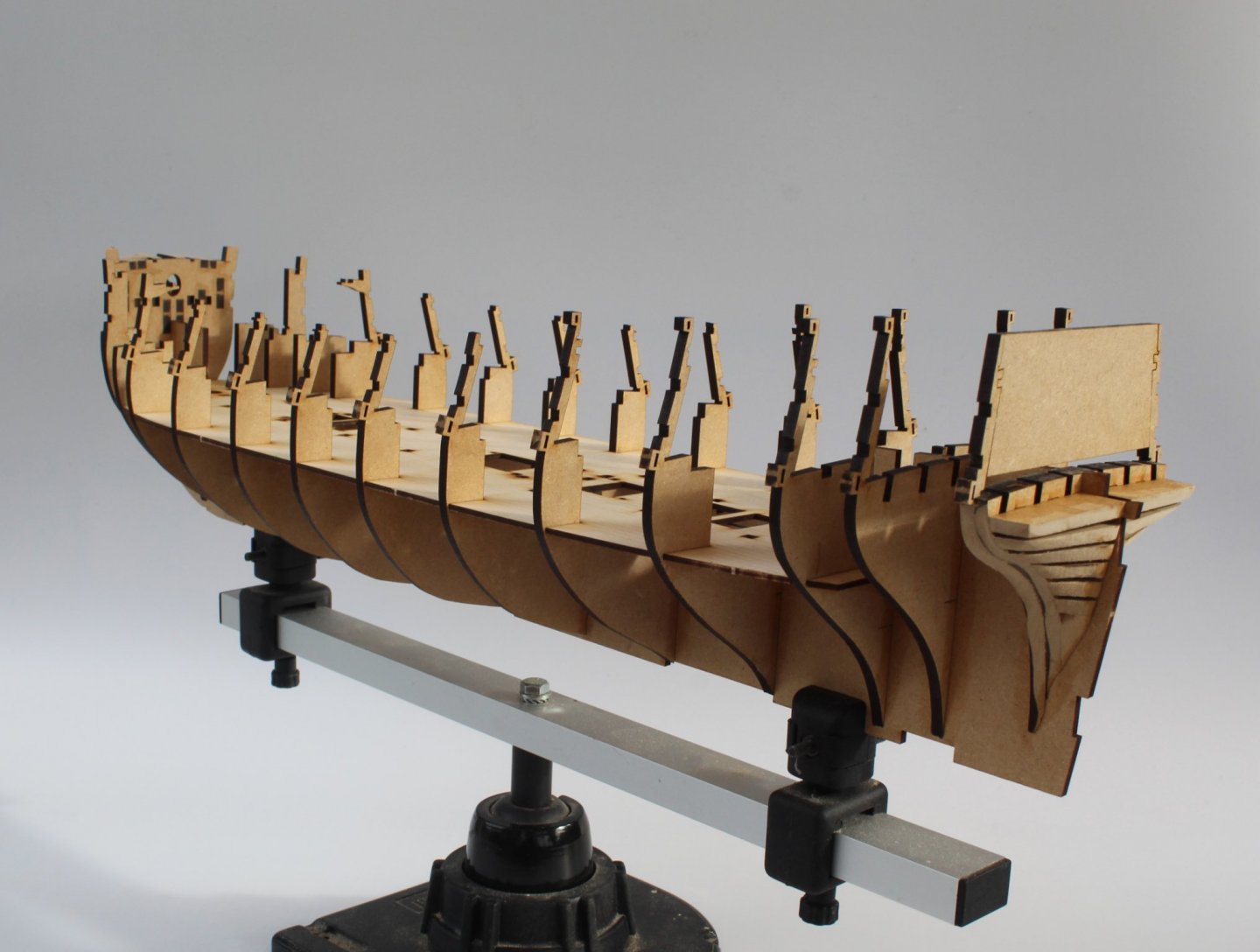
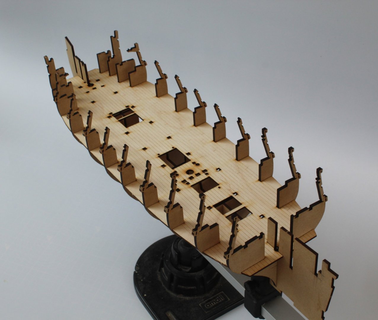
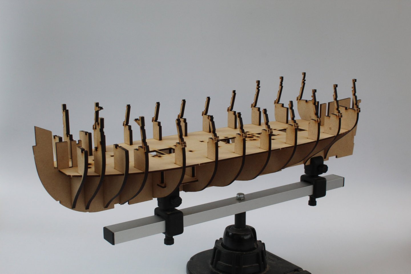
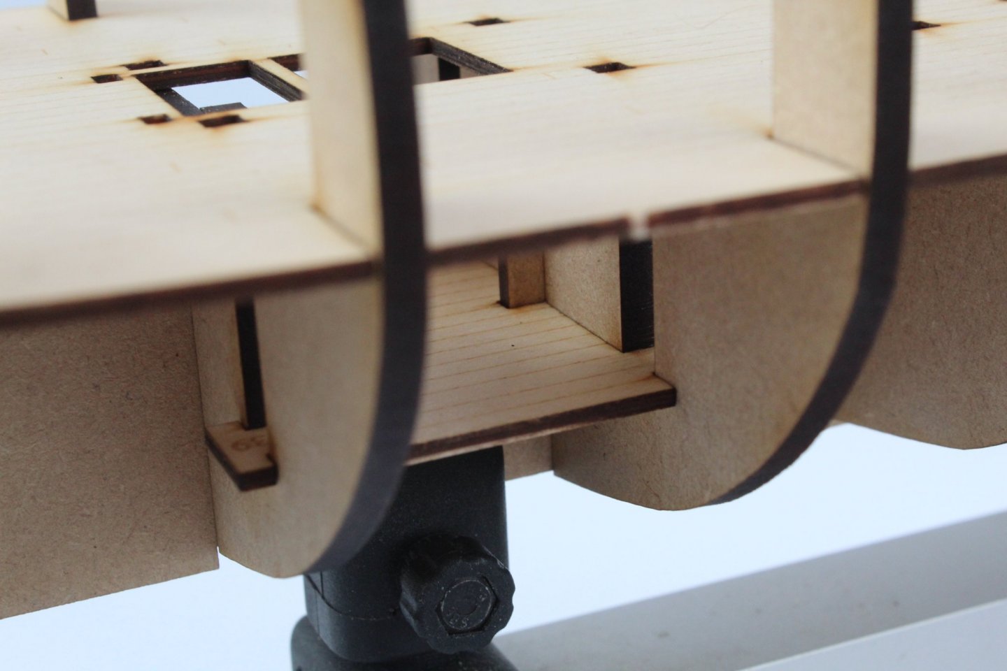
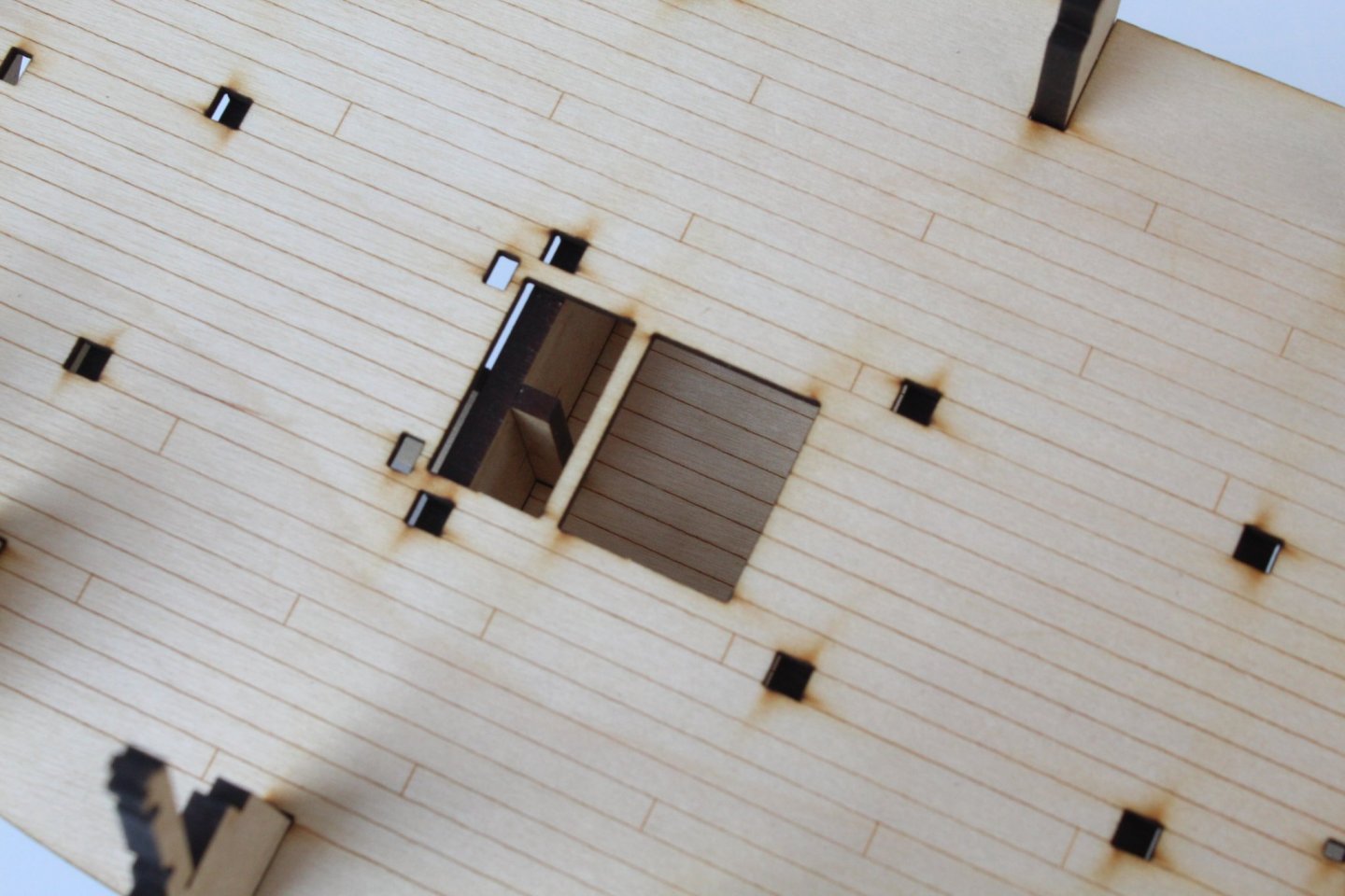
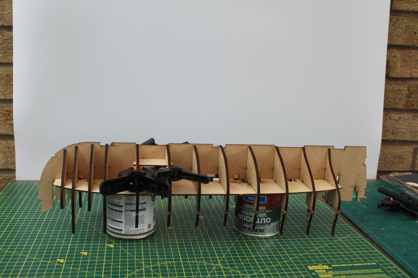
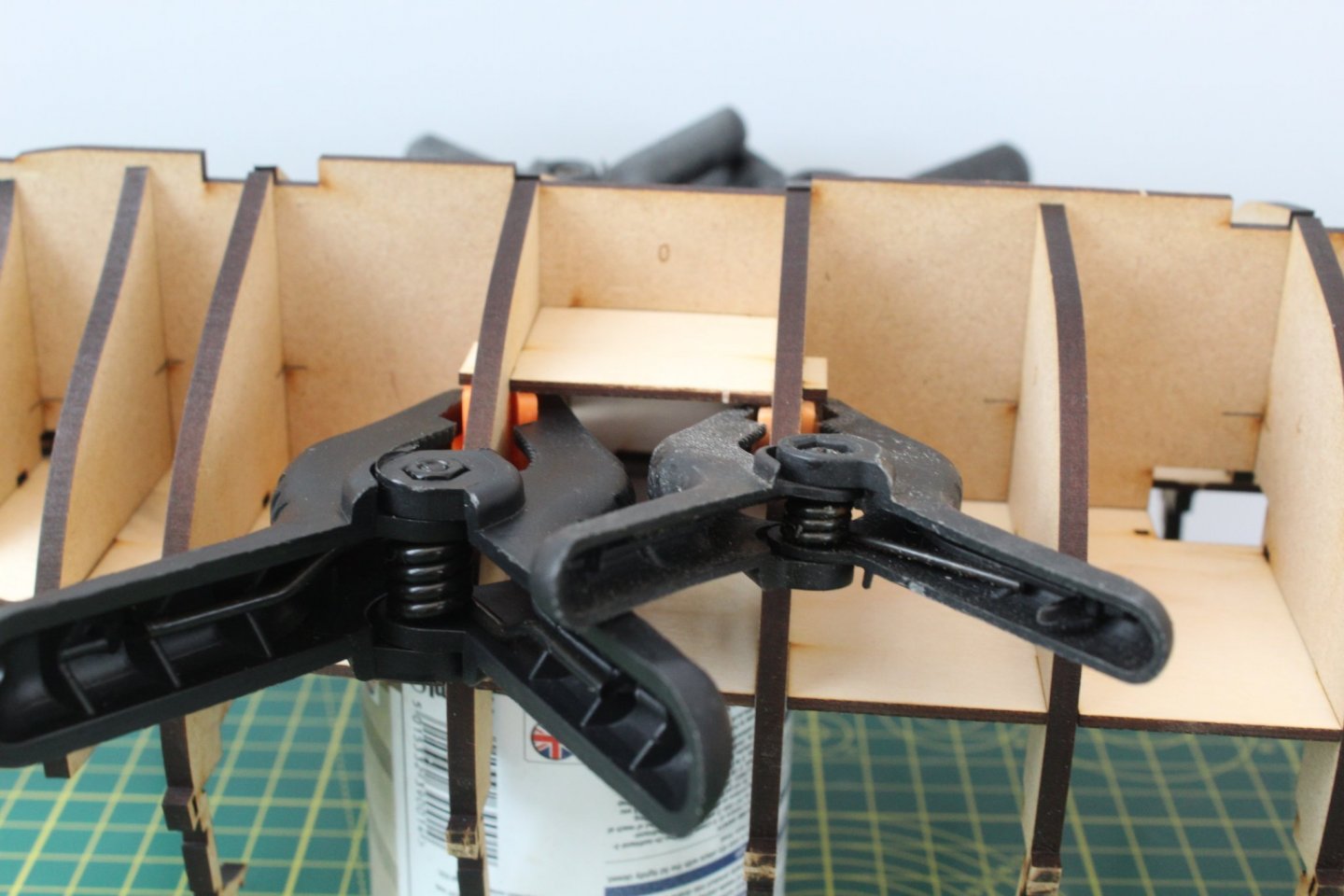
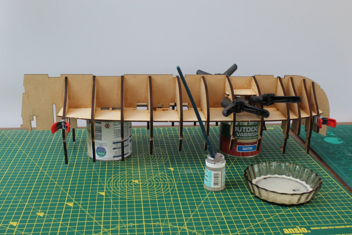
BULKHEADS AND LOWER DECK ASSEMBLY BUILD MANUAL STEPS 27-40 LINK TO MY BUILD LOG INDEX Tools Used Craft knife Flory sanding stick Titebond original glue Old paint brush Clamps Gathering the materials required The first task was to identify and remove the bulkheads (1-1, 2, 2-2, 3, 4, 5, 6, 7, 8, 9, 10, 11 and 12) from the MDF sheets and then using a standing stick the excess tab material was removed from each part. It was not necessary to remove the laser char for the edges at this stage. Assembly Process – Bulkheads 1-1 to 11 The bulkheads were then slotted in turn to the keel. They are not glued during this phase of the build process. I have shown all the bulkheads in the picture below. Assembly Process – Lower Deck & Orlop Deck Next the Orlop Deck Section (39) was removed from the sheet and added to the keel after the excess tab material was sanded smooth. It is not glued in place for the time being. The Lower Deck section (40) was removed from the sheet and added to the keel after the excess tab material was sanded smooth. It is not glued in place for the time being. Assembly Process – Adding the glue to Bulkheads 1-1 to 11 and decks The dry fitted keel assembly was then positioned upside down, using a couple of tin cans to keep the bulkhead ears safe. Using a paint brush a diluted pva solution was applied to the various joints between the deck, bulkheads. I used some clamps to ensure the Orlop deck was held in the correct position. I also used some clamps at each end of the lower deck to ensure it made a firm contact with the bulkheads. I waited for 4 hours before moving on to the next task, which was plenty of time for the glue to start to cure. Assembly Process – Bulkheads 1, 12 & 13/13-1 The keel was turned the right way up (after 4 hours) so the three remaining bulkhead assemblies (1, 12 & 13) could be fitted and glued in place, once again brushing a diluted pva solution in the various joints. The completed assembly will now be left overnight to allow time for all the glue to fully cure.

-
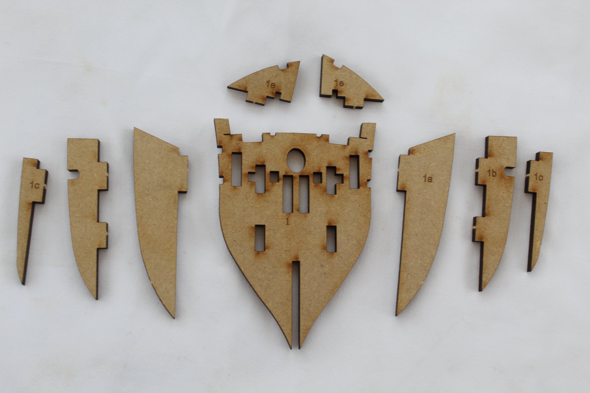
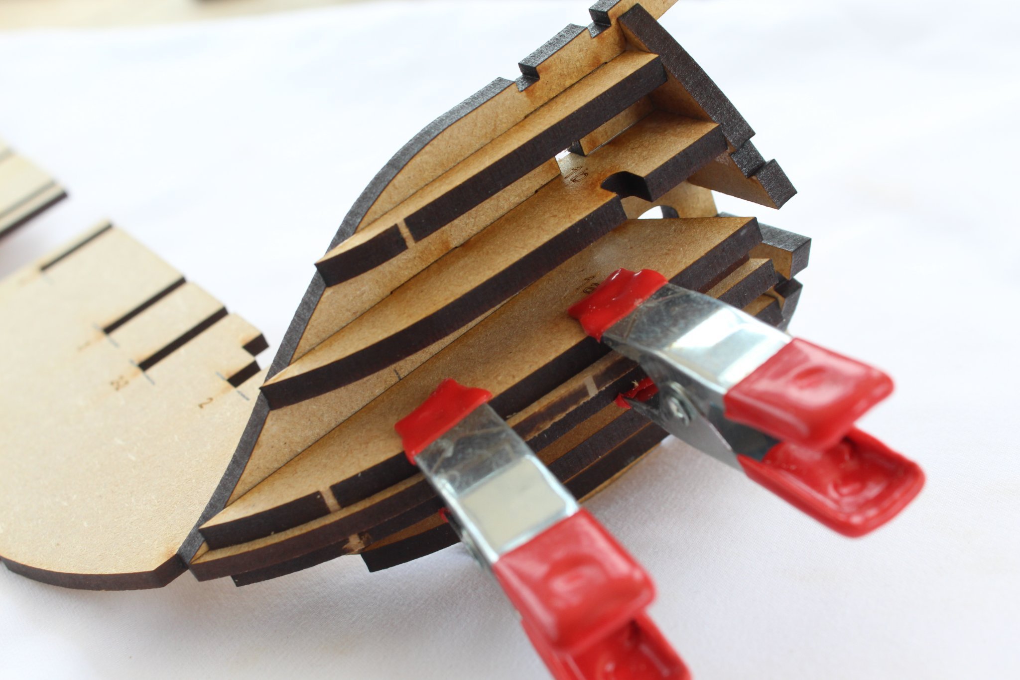
BOW BULKHEAD ASSEMBLY BUILD MANUAL STEPS 18-25 LINK TO MY BUILD LOG INDEX Tools Used Craft knife Flory sanding stick 120 and 400- grit sandpaper Titebond original glue Old paint brush Amati’s special cleaner sanding block, reference B7140 Ginour cordless rotary multi-tool Clamps Gathering the materials required The following kit parts are required for this section of the build: 0, 1, 1a (x2), 1b (x2), 1c (x2), 18 (x2) I made a cut on either side of the securing tabs when removing each part from the MDF sheet to minimise the excess tab material. As each part was removed a sanding stick was used to remove the remanets of the tab material. It was necessary to remove the laser char for the edges as this assembly will be shaped later in this build section. Assembly Of First Bulkhead Pattern Pair Bulkhead 1 was slotted to the keel but not glued in place. A thin coating of glue was applied to the contact edges of the 2 x 1a bow bulkhead patterns and they added to bulkhead 1. Clamps were used to ensure they were held in the correct position as the glue cured ensuring bulkhead 1 is held at 90 degrees to the keel. Great care was taken to ensure no glue spilled in the bulkhead / keel joints. Assembly Of Remaining Bulkhead Pattern Pairs The remaining bow bulkhead patterns were then glued in place on bulkhead 1 (2 x 1b, 2 x 1c and 2 x 18) once again I made sure that no glue spilled in the bulkhead / keel joints. As an added precaution I removed this bulkhead assembly from the keel as the cure started to cure. Shaping Of Bow Bulkhead 1 Assembly Once the glue had fully cured I started the shaping process using the rotary tool. I then used a mixture of sanding sticks, sandpaper and the sanding block to complete the task. The bulkhead may require more sanding during the hull fairing process later in the build.


-
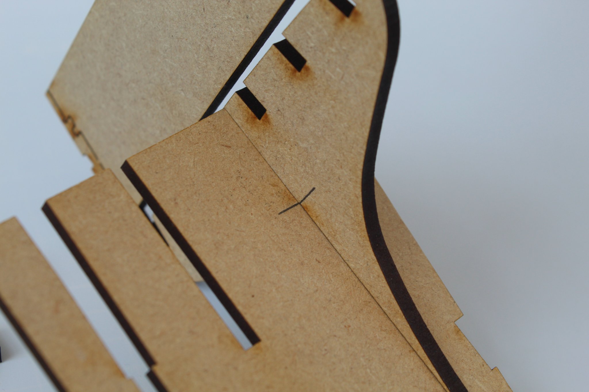
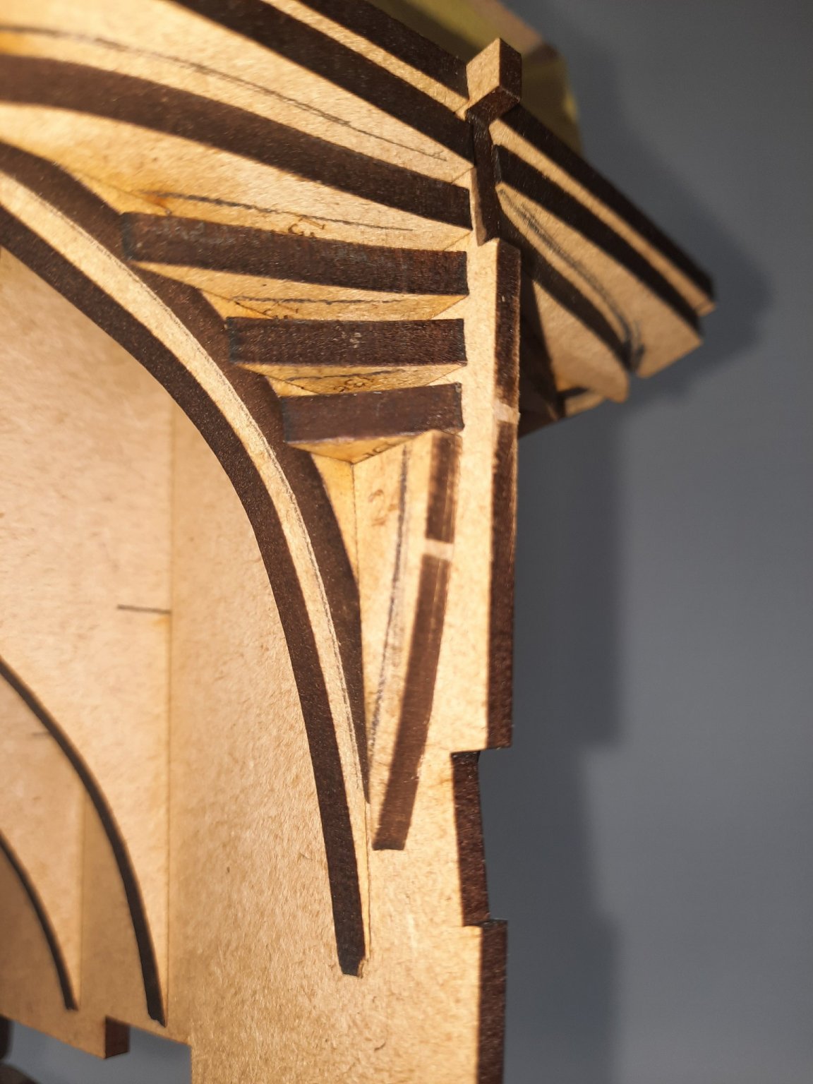
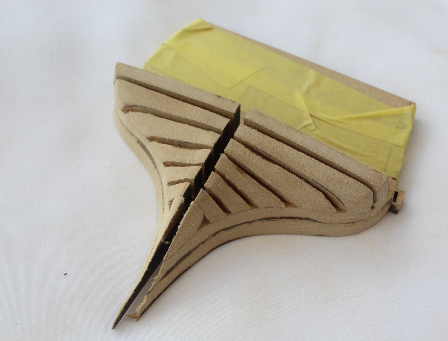
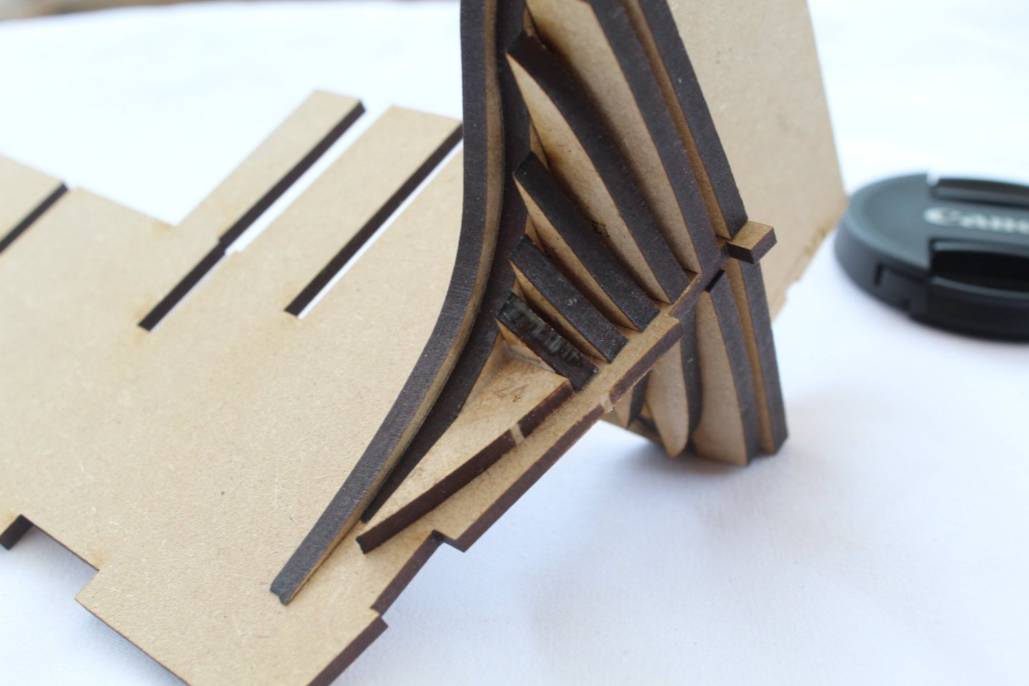
Thanks @BobG It is a bit difficult to explain, but here goes. If you look at the photo below. I drew a line from the top of part 24 where it aligned with the outer edge of part 13f to the bottom where it made contact with bulkhead 13-1. I then marked the patterns 13a to 13f which extended past the outside edge of bulkhead 13-1. With the patterns 13a to 13f I simply drew a pencil line on the bottom edge of each pattern which was the same shape as the top edge of the pattern below it. When I started shaping I removed all the pattern material which extended past the outside edge of the bulkheads. I then worked on shaping the area around part 24 and then worked upward. I took my time and kept checking the shaping at very regular intervals. Hope that helps

-
I probably spend more time writing the build log and taking photos than on the actual build🤣
-
Thanks Chris
-
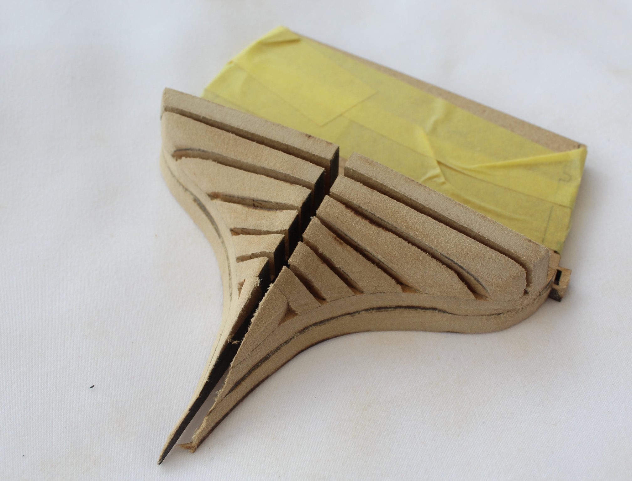
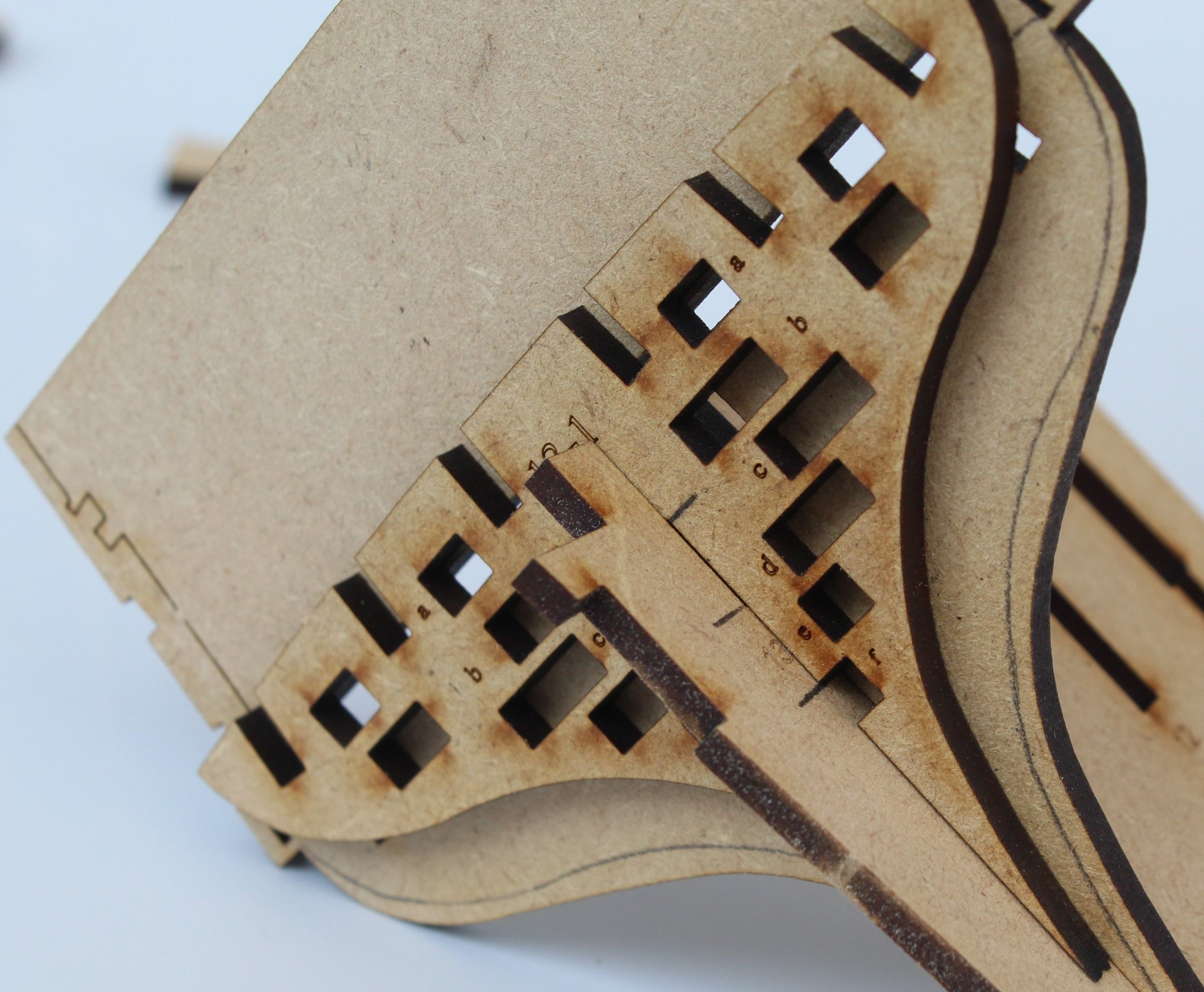
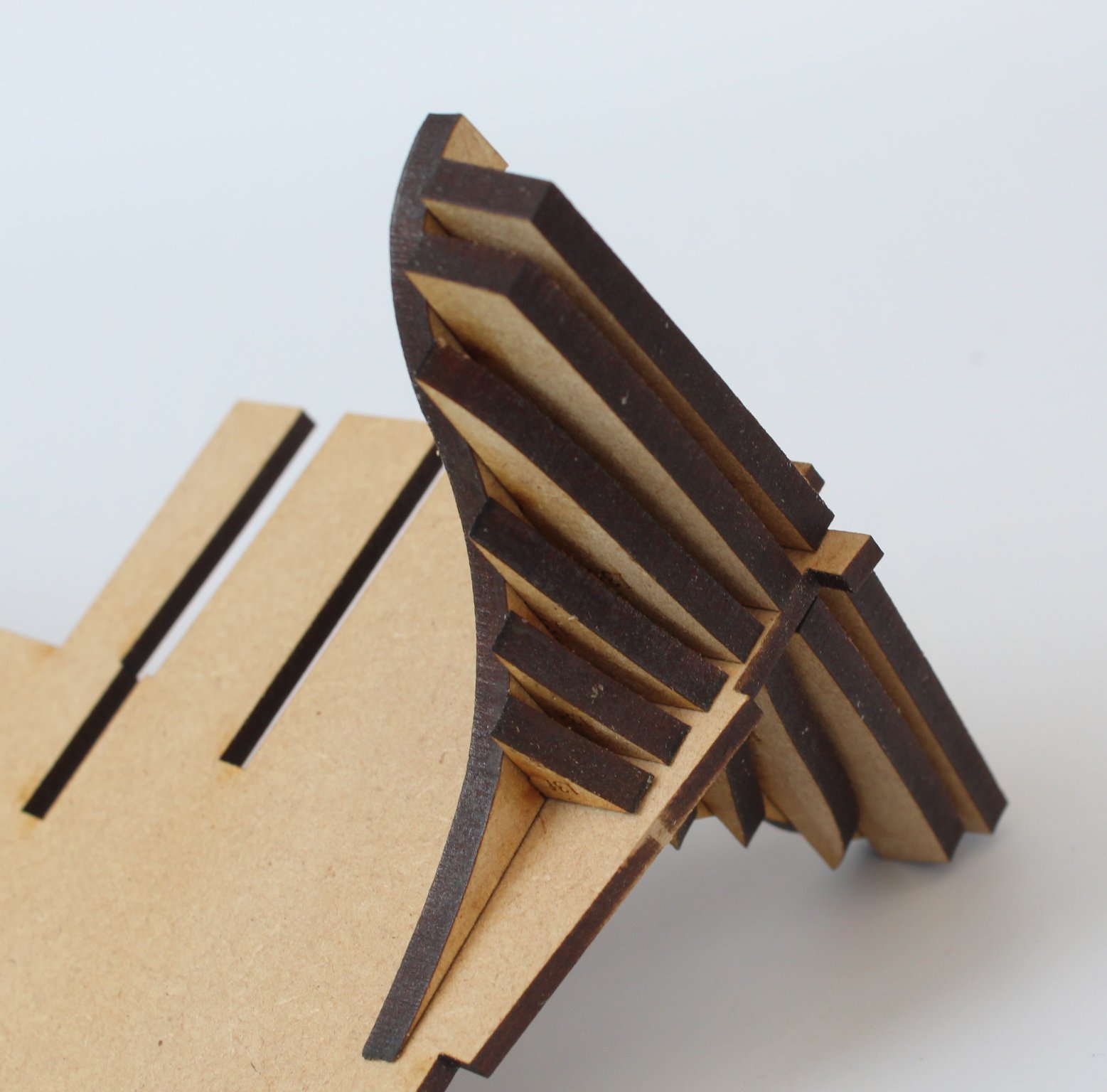
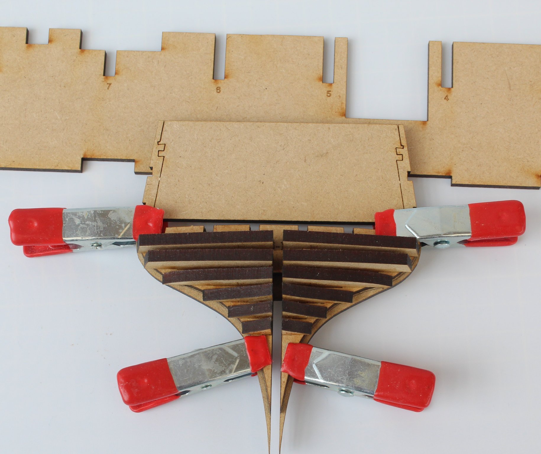
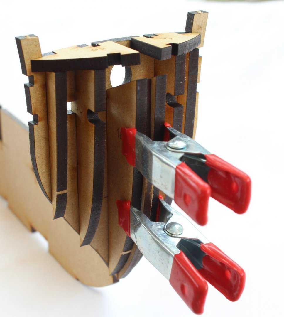
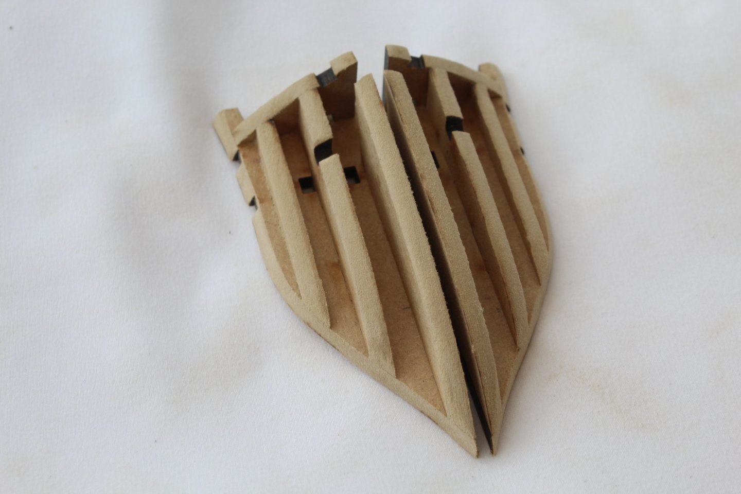
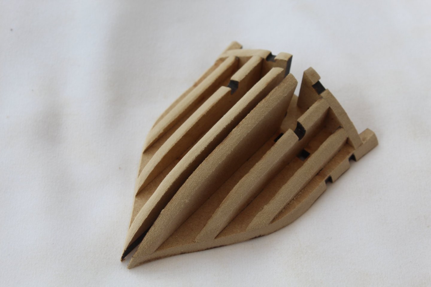
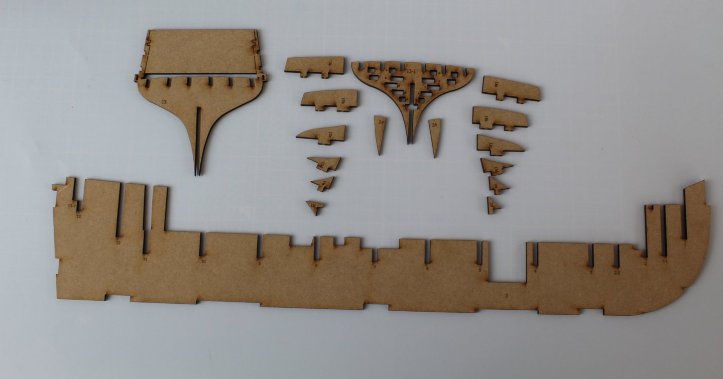
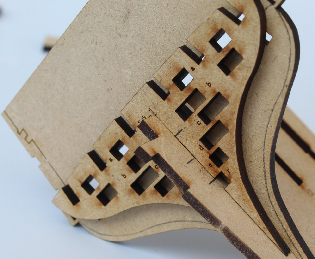
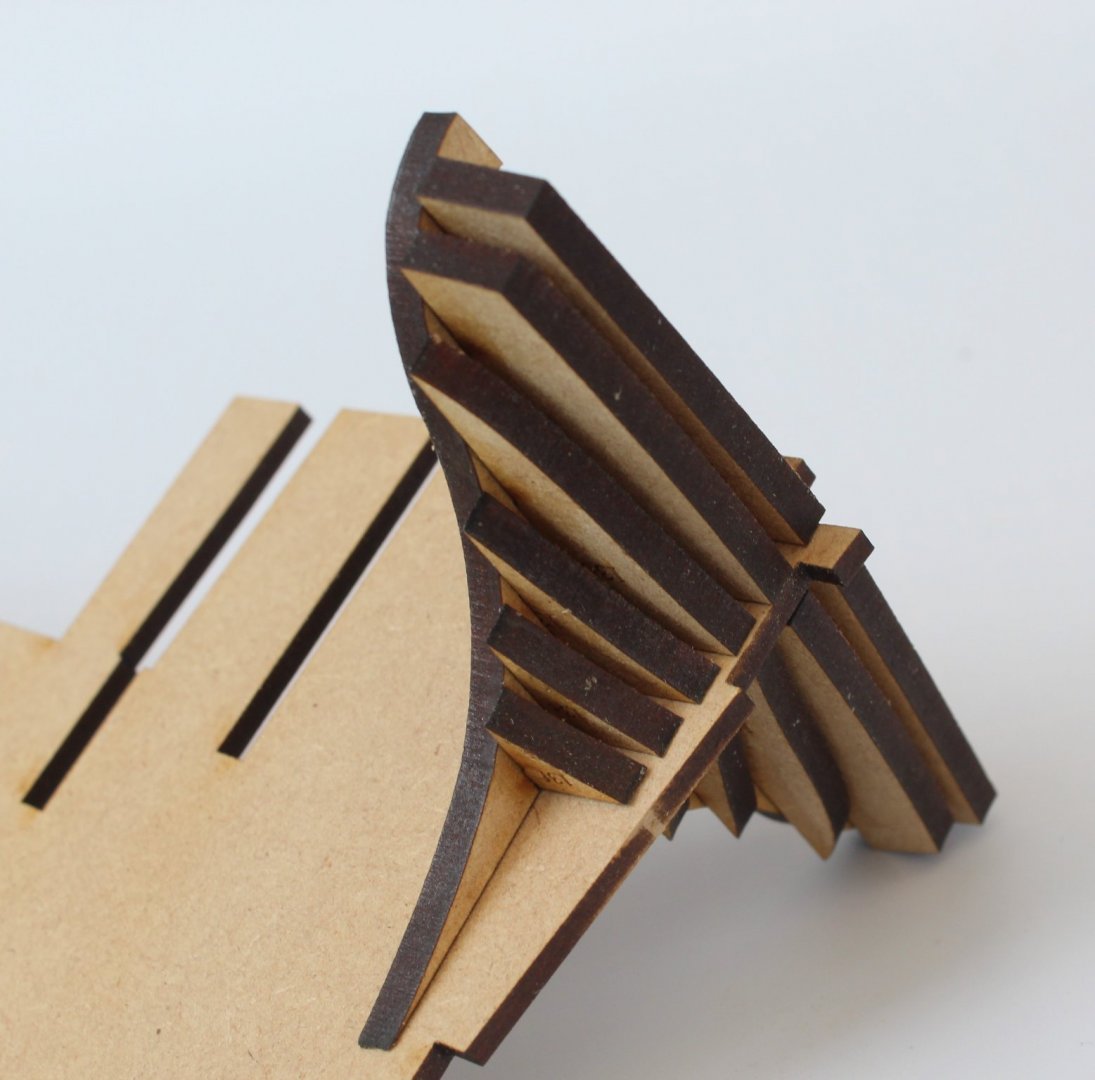
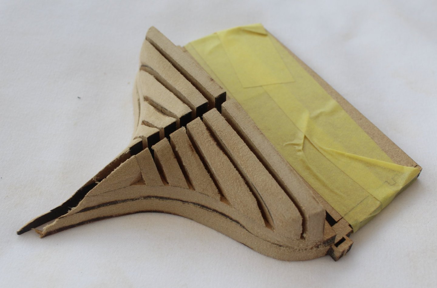
STERN BULKHEAD 13 & 13-1 ASSEMBLY BUILD MANUAL STEPS 6-16 LINK TO MY BUILD LOG INDEX Tools Used Pencil Craft knife Clamps Flory sanding stick 120 & 400- grit sandpaper Titebond original glue Old paint brush Amati’s special cleaner sanding block, reference B7140 Ginour cordless rotary multi-tool Gathering the materials required The following kit parts are required for this section of the build: 0, 13, 13-1 13a (x2), 13b (x2), 13c (x2), 13d (x2), 13e (x2), 24 (x2) I made a cut on either side of the securing tabs when removing each part from the MDF sheet to minimise the excess tab material. As each part was removed a sanding stick was used to remove the remnants of the tab material. Build Tip-1 In order to ensure the bulkheads are correctly seated I find it beneficial to mark the bottom of the slots, both the keel and on each bulkhead. When the bulkheads are correctly seated pencil marks will be aligned. Build Tip-2 I placed both bulkheads 13 and 13-1 in their respective slots on the keel and so I could mark the outer edge of bulkhead 13-1 on bulkhead 13. This provides a good guide to the where the glue needs to be applied when the two bulkheads are glued together later in this task. Adding the bulkhead patterns Bulkhead 13-1 was then removed from the keel so the two sets of the bulkhead patterns (13a-13f) could be glued in position. Bulkhead 13-1 was then put to one side to allow time for the glue to cure. Assembly Of Bulkhead 13 and 13-1 A liberal coating of glue was brushed to the lower section of bulkhead 13 (in the marked area) then bulkhead 13-1 was slotted back to the keel. It is important to note that the bulkhead 13 & 13-1 assembly is not glued to the keel during this process as it needs to be removed for shaping once the glue has fully cured. I added some clamps and removed the assembly from the keel as the glue started to cure as an added precaution. Adding The stern planking patterns With the 13-1 bulkhead assembly back on the keel the two stern planking patterns were glued in place and as the glue started to cure I once again removed the assembly from the keel. Shaping Of Stern Bulkhead 13 & 13-1 Assembly Once the glue had fully cured (overnight), as per the build manual instructions, tape was added to the top section of bulkhead 13 for protection of the infill part. I made some pencil marks to indicate the material to be removed. I started the sanding and shaping process using my Ginour cordless rotary multi-tool, as my dremel had stopped working and was beyond repair. I then used a mixture of sanding sticks, sandpaper and the sanding block to complete the process. I am sure more sanding will be required once the hull is ready to be faired prior to the first planking.


-
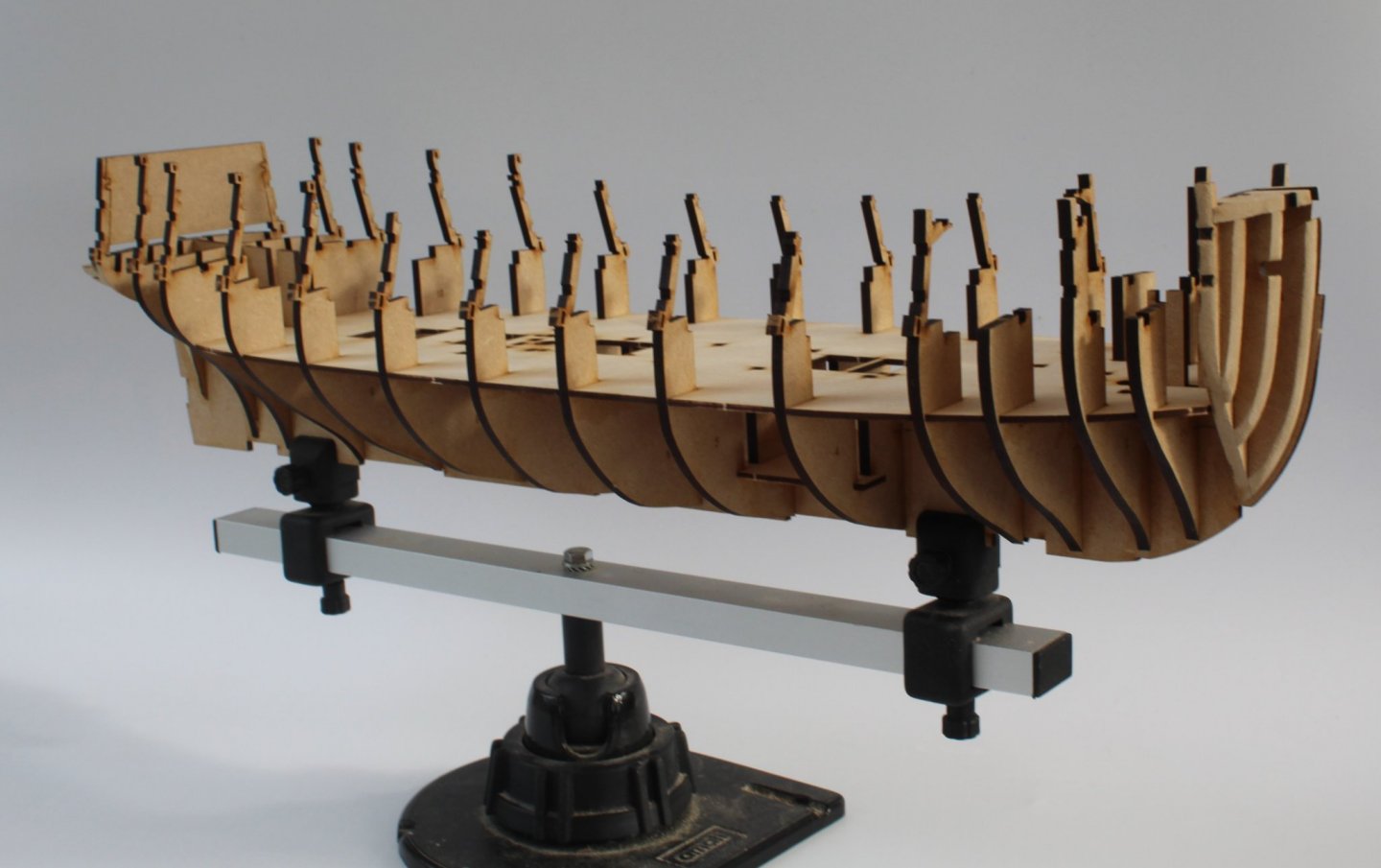
She sure is a nice shape, and I will be fairing these assemblies a little bit at a time.
-
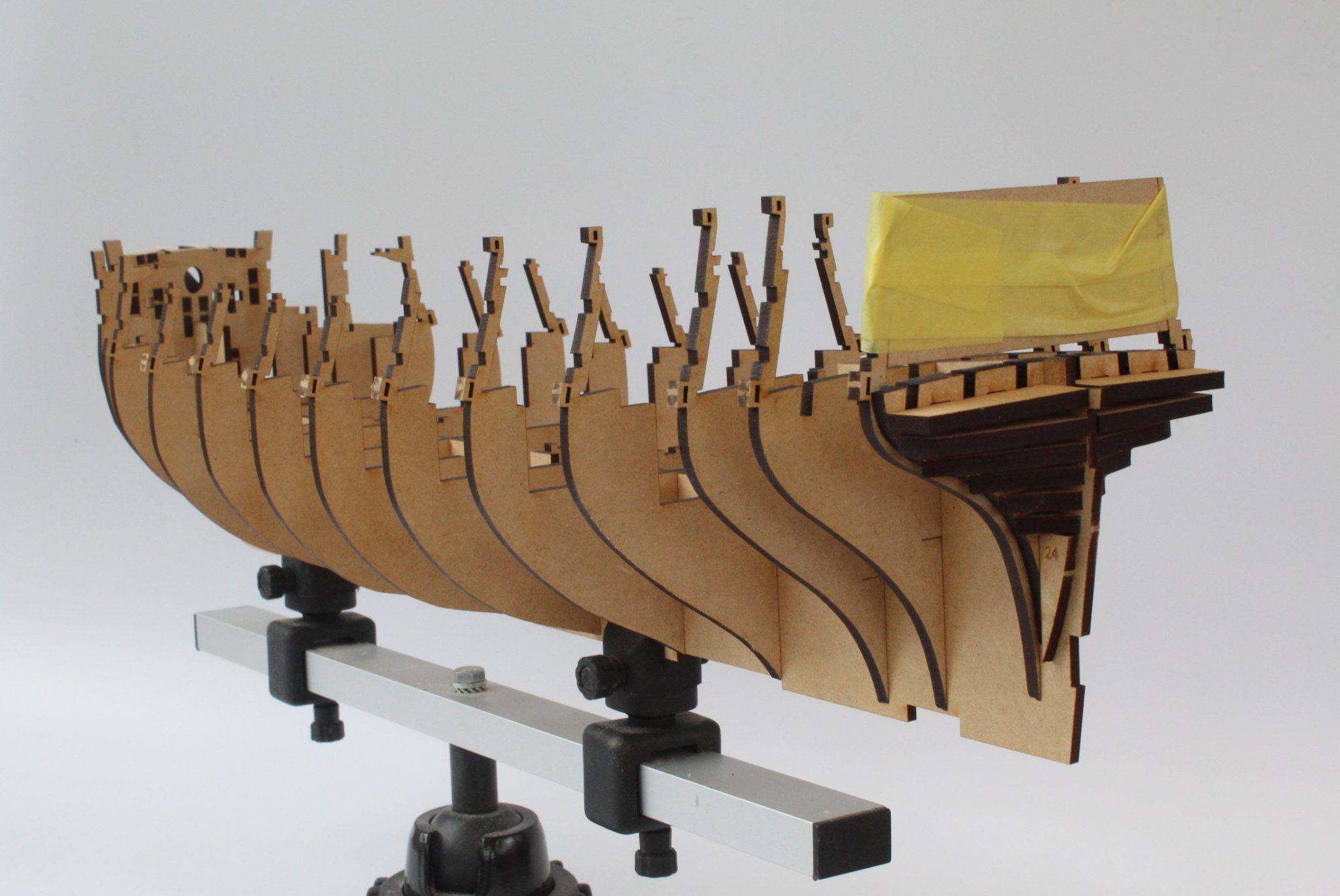
This is an "unofficial" build log post, so is not linked to my build log index and is not in the format I'm planning to use for each completed task post. I have had a good day in the shipyard. I am ready to start the off boat fairing of bulkhead 13 assy (stern) and bulkhead 1 (bow) assy. Before I make a start I have drawn some pencil lines to get an idea of how much material needs to be removed. There is quite a lot of material to remove so I will summon up the courage overnight and make a start in the morning. Close up of bulkhead 13 assy showing fairing pencil lines Keel with dry fitted bulkheads Keel with dry fitted bulkheads with tape protecting the infill


-
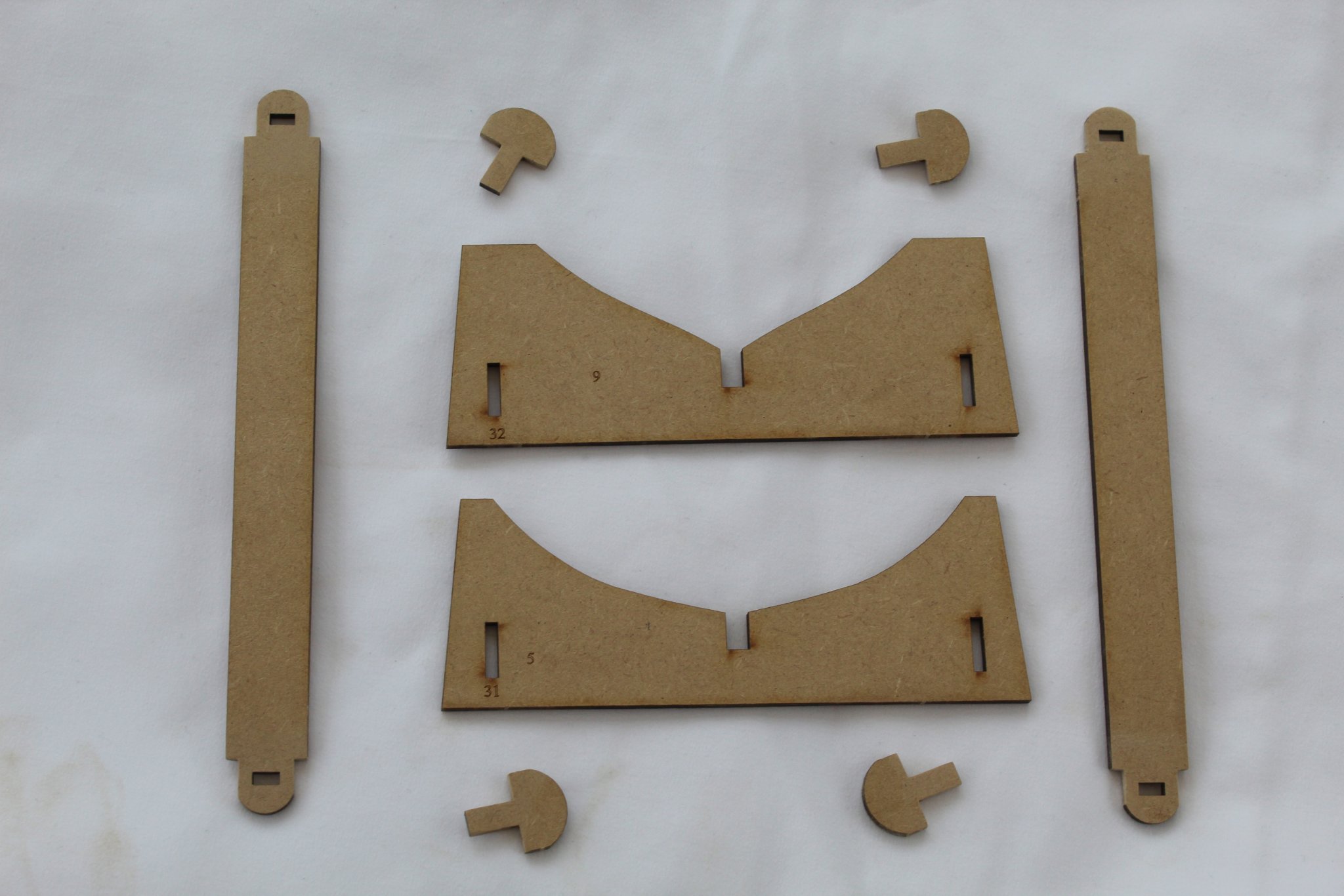
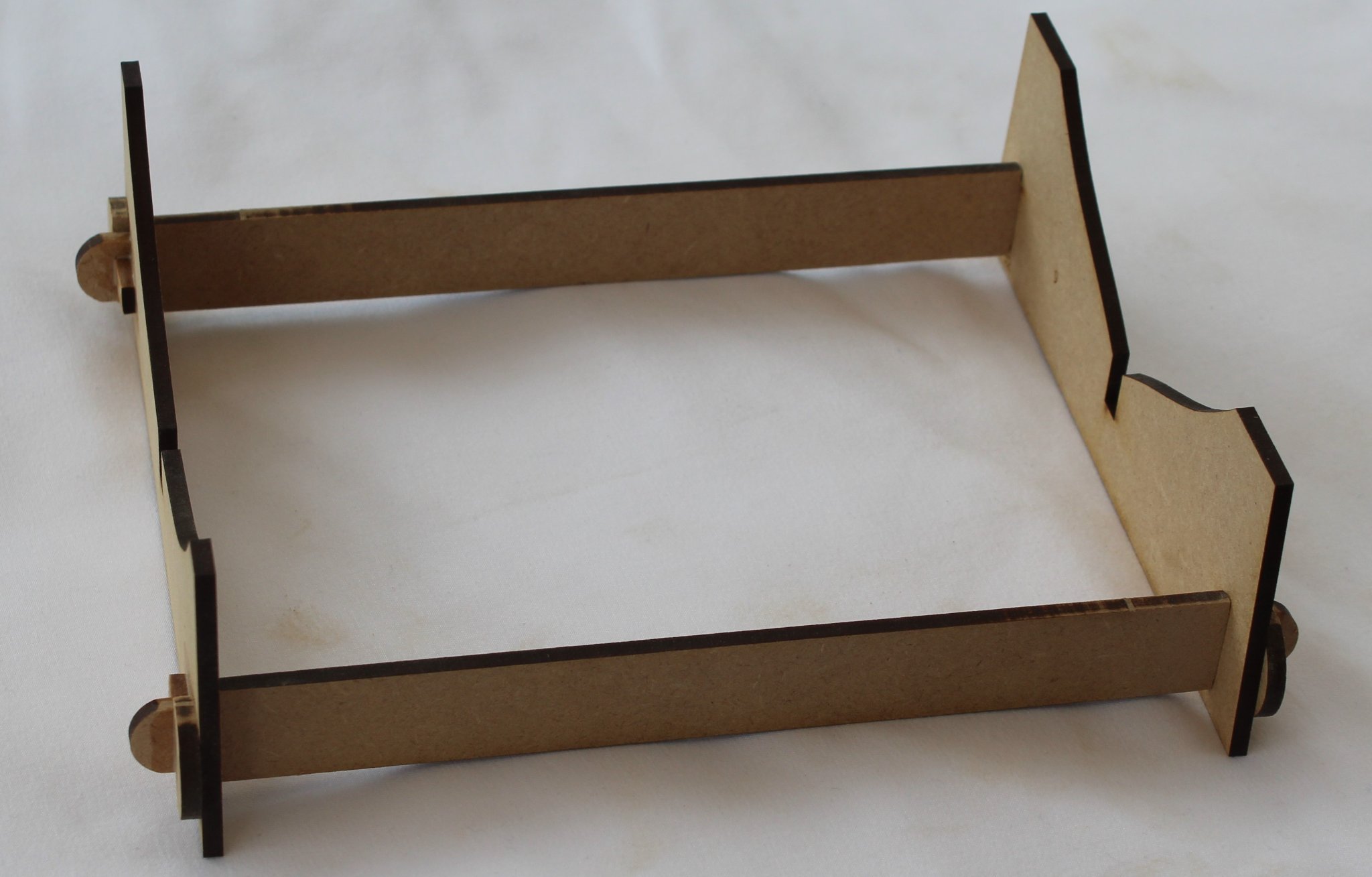
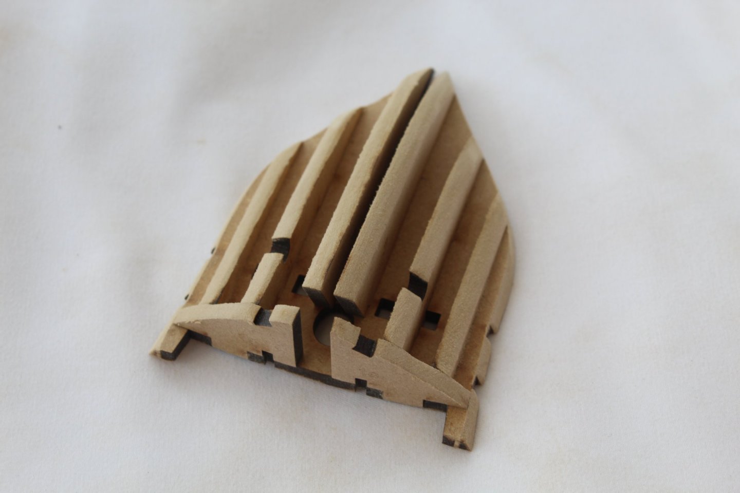
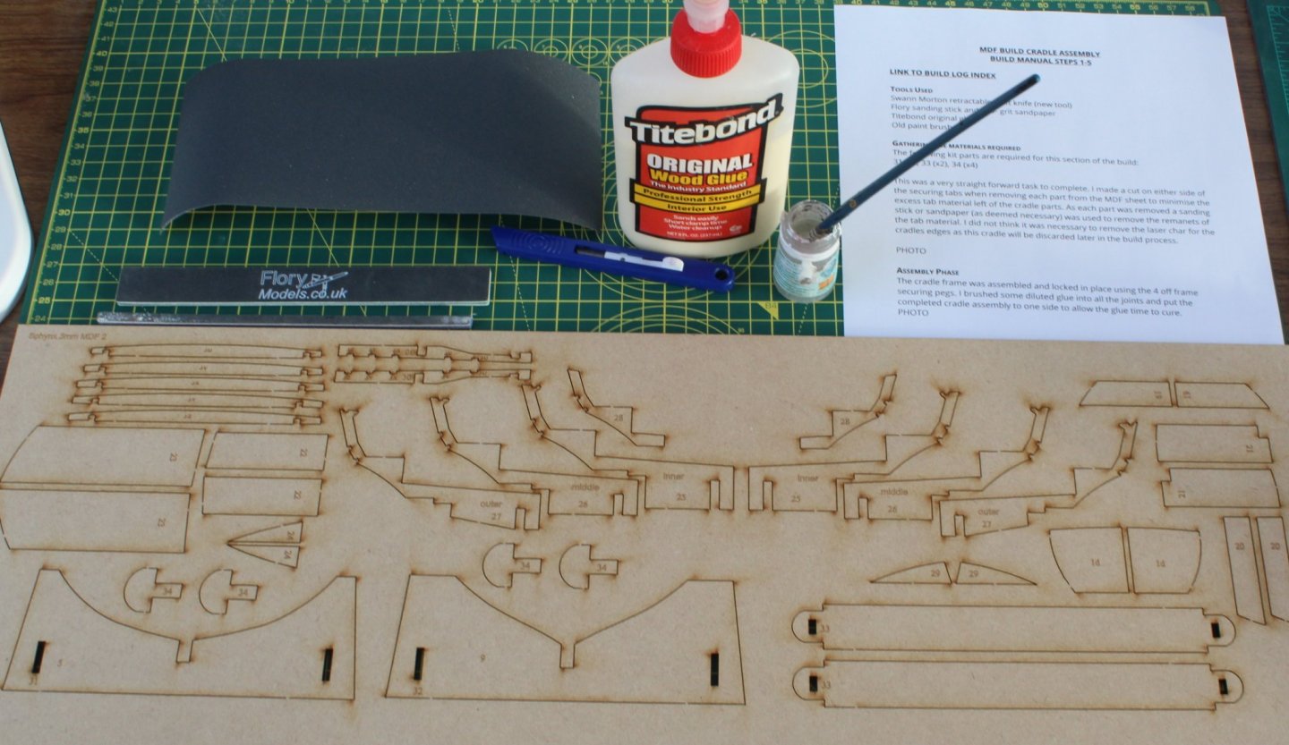
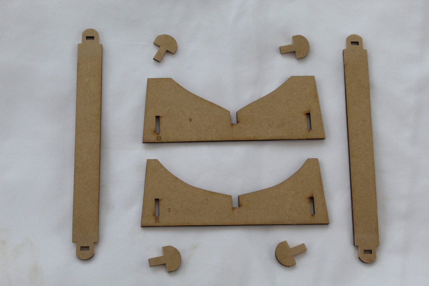
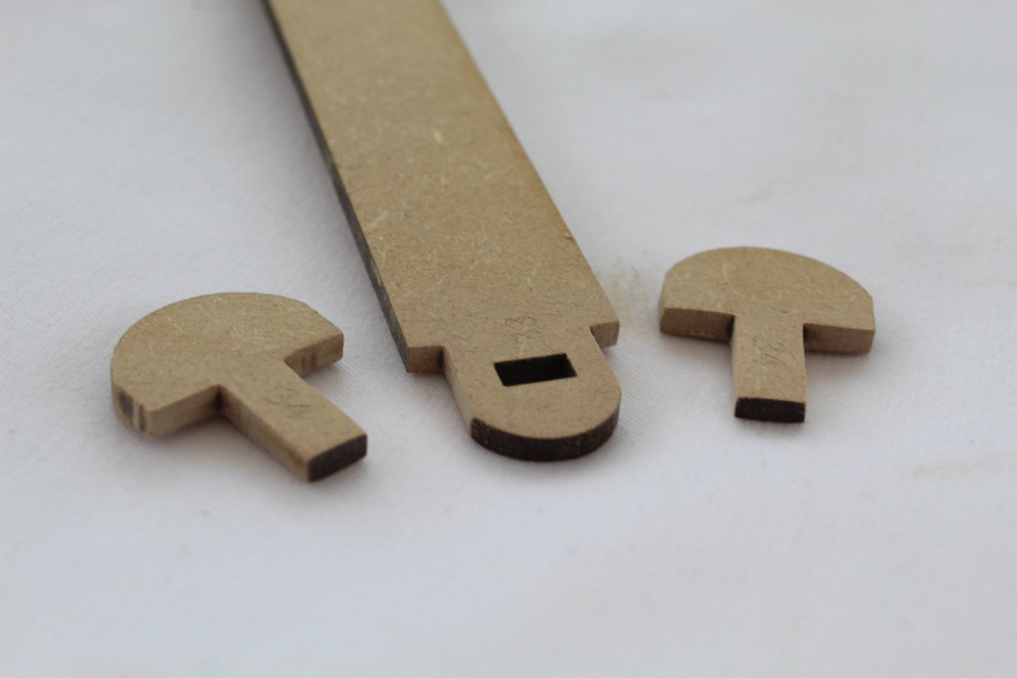
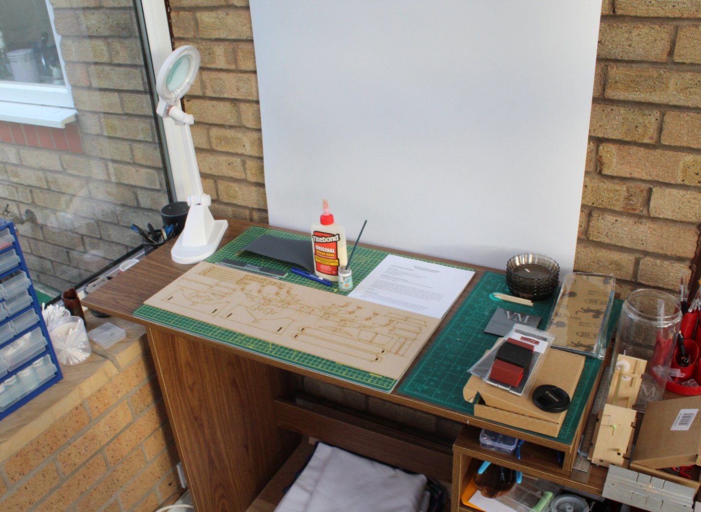
MDF BUILD CRADLE ASSEMBLY BUILD MANUAL STEPS 1-5 LINK TO MY BUILD LOG INDEX Tools Used Craft knife Flory sanding stick and 400- grit sandpaper Titebond original glue Old paint brush and small water pot Gathering the Materials Required The following kit parts are required for this section of the build: 31, 32, 33 (x2), 34 (x4) (all located on the 3mm MDF 2 sheet) Photograph of my work area, ready to start work on HMS Sphinx Close up photograph of the tools and material for this task. The sheet of paper in the top right of the picture is a printout of my prebuild notes for this task. I made a cut on either side of the securing tabs when removing each part from the MDF sheet to minimise the excess tab material left of the cradle parts. As each part was removed a sanding stick was used to remove the remnants of the tab material. This is a photograph of the cradle parts ready for assembly. Assembly Phase When I started to assembly the cradle I found it necessary to remove the laser char from the tab ends of parts 33 and 34 to enable them to fit into the locating slots. Photograph of the tab ends after sanding. After the laser char had been removed from the tab ends the cradle frame was assembled without any problems and locked in place using the 4 off frame securing pegs. I brushed some diluted glue into all the joints and put the completed cradle assembly to one side to allow the glue time to cure. Photograph of the completed cradle assembly

-
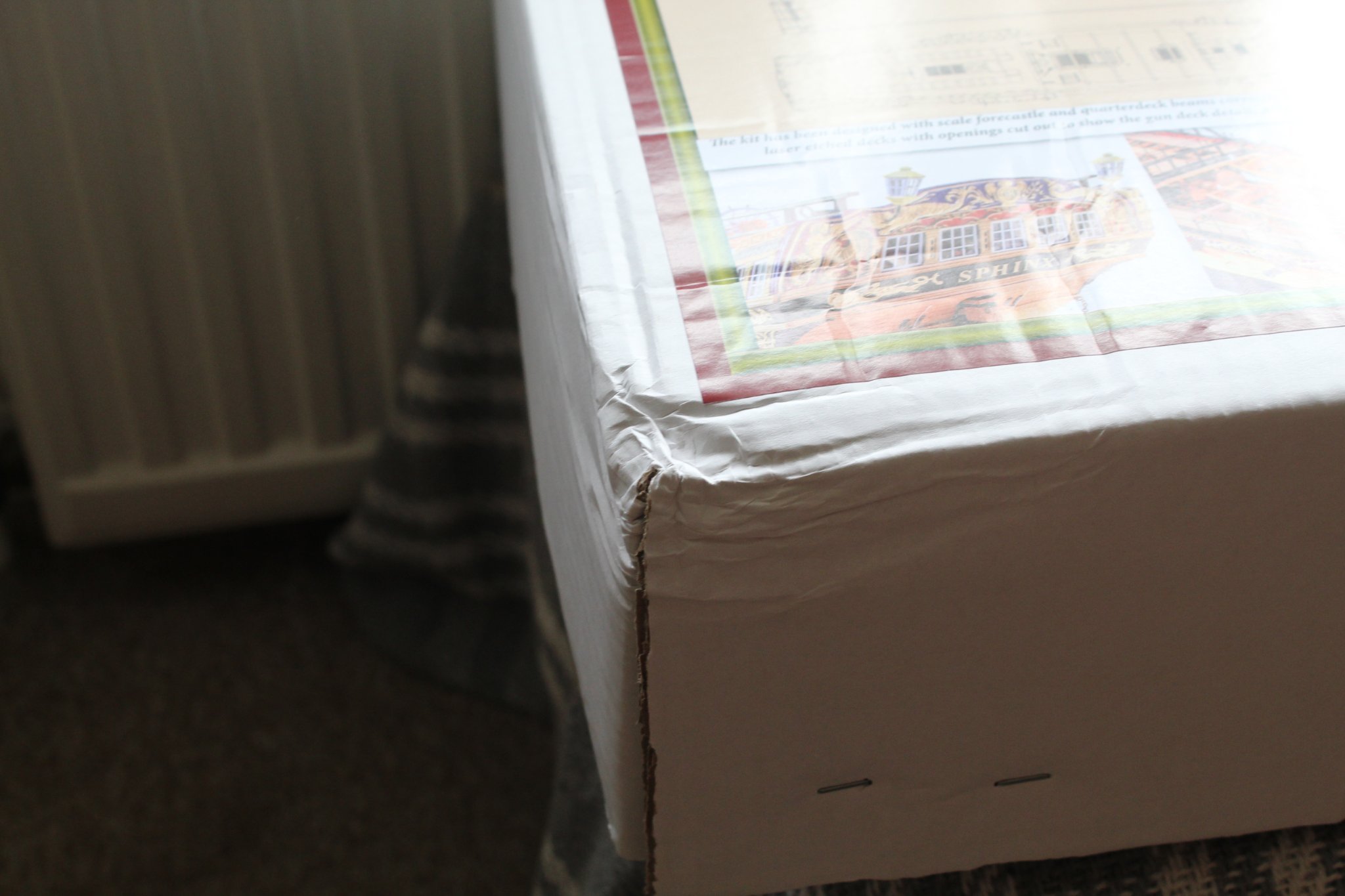
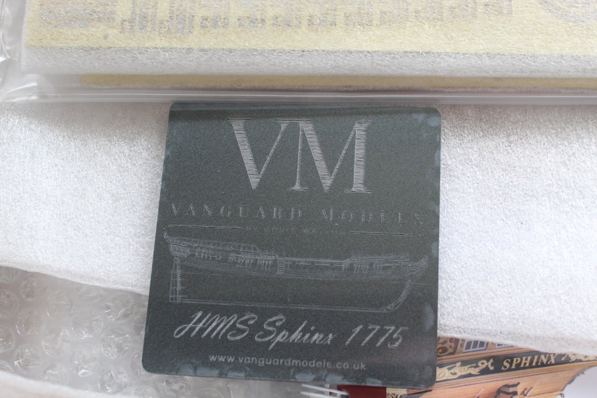
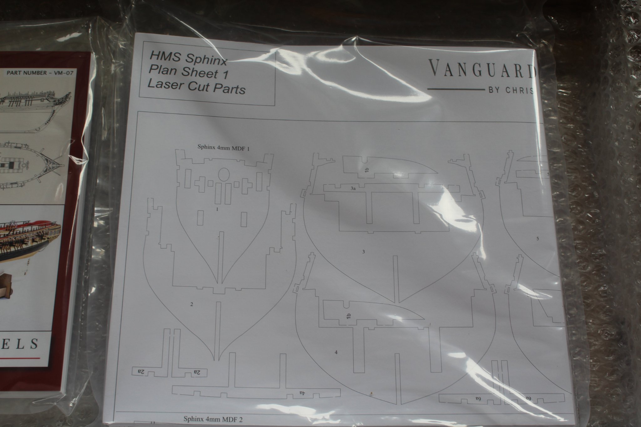
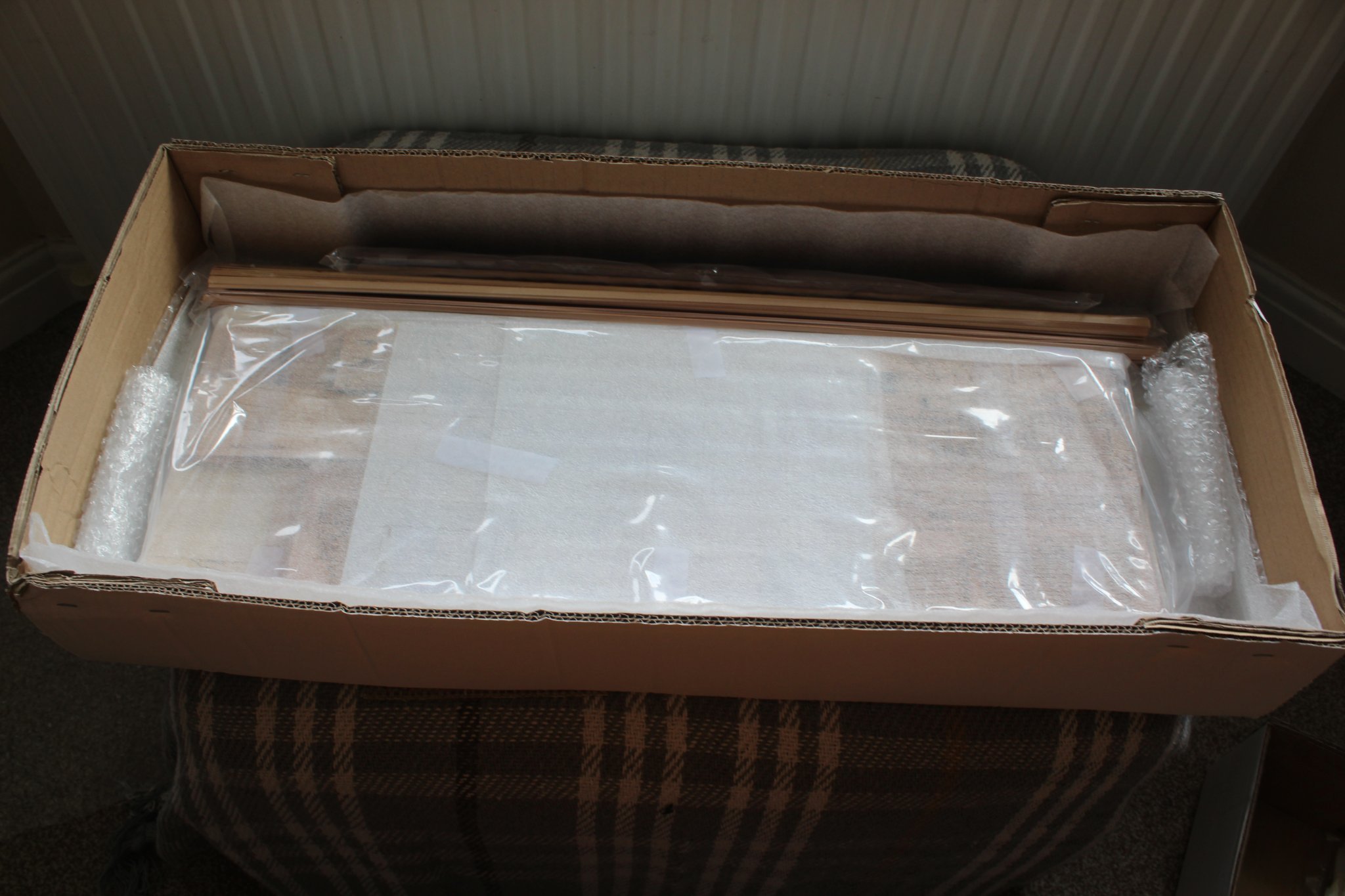
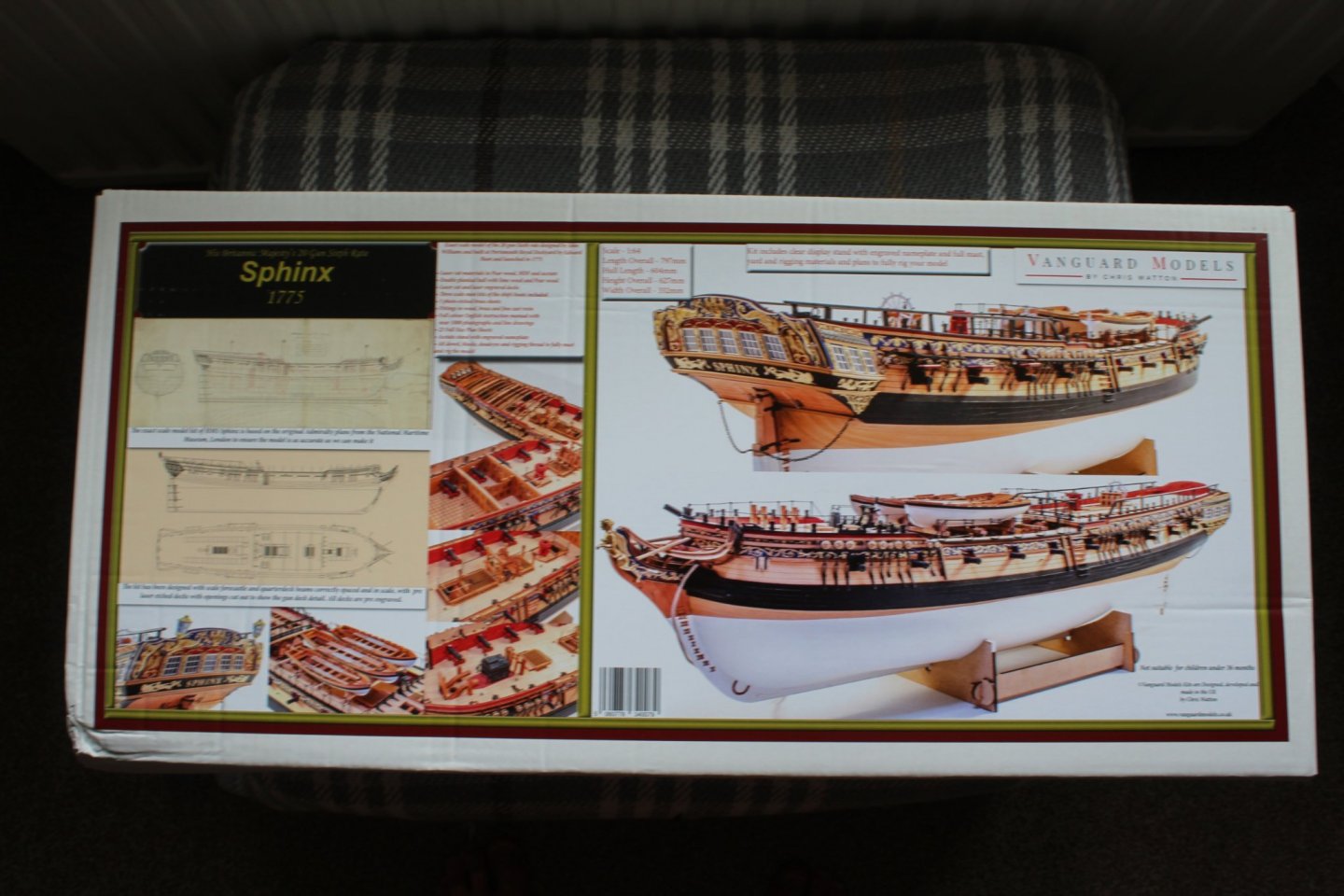
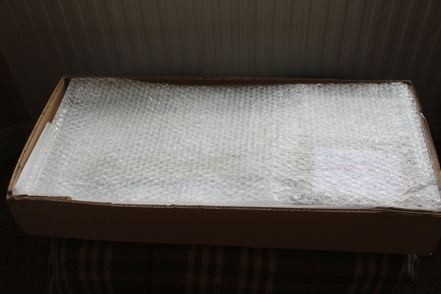
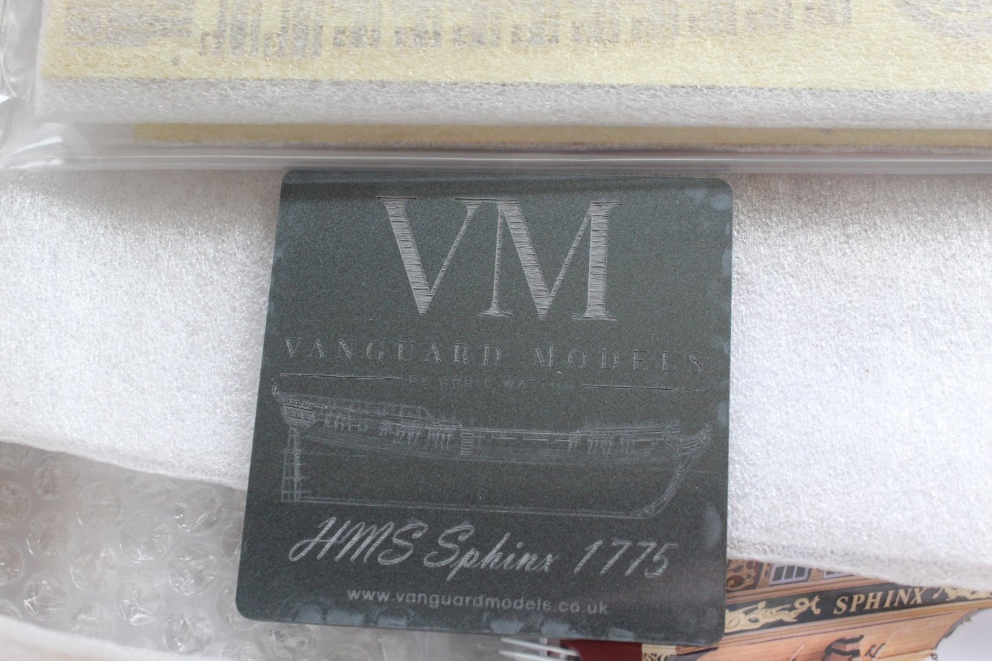
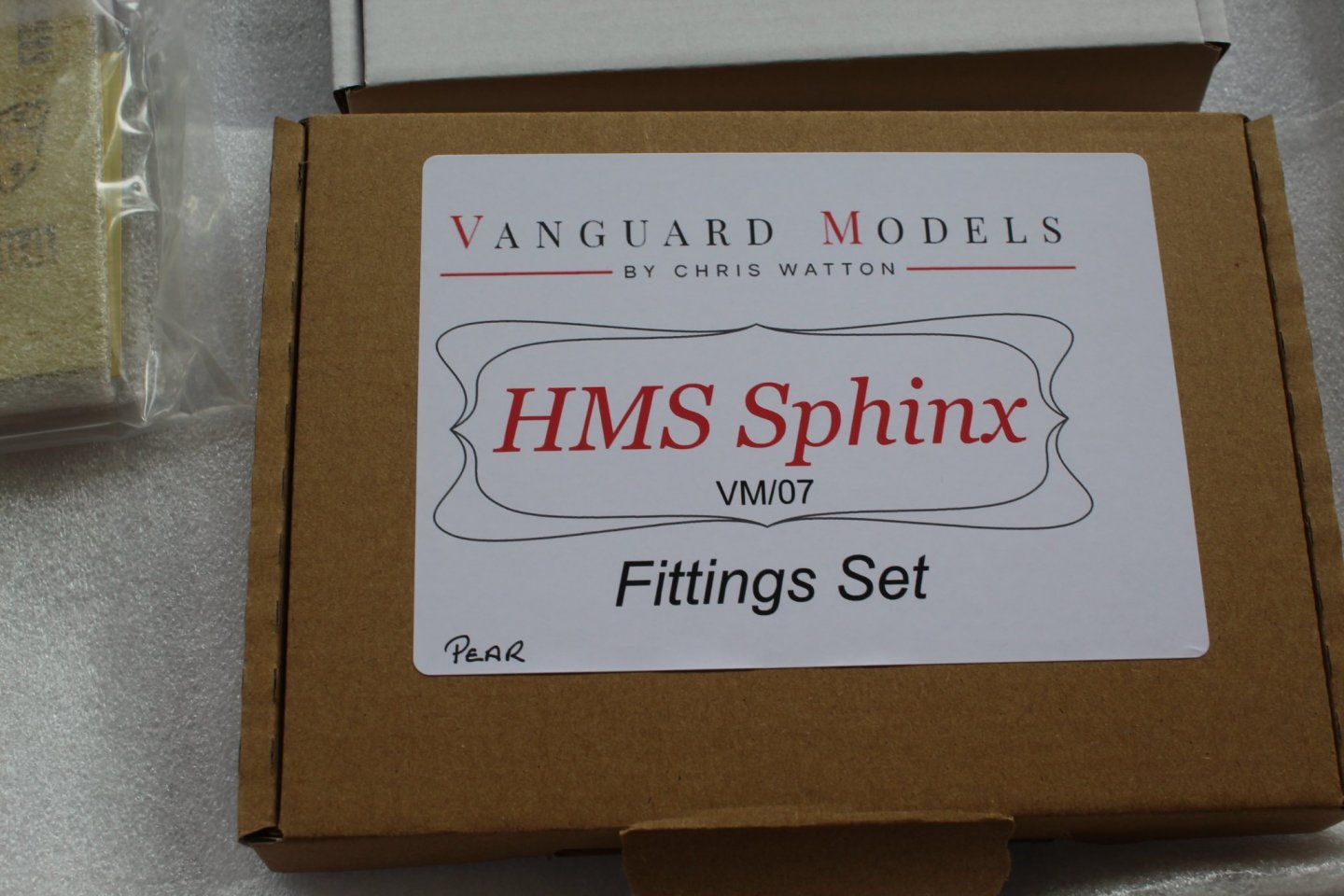
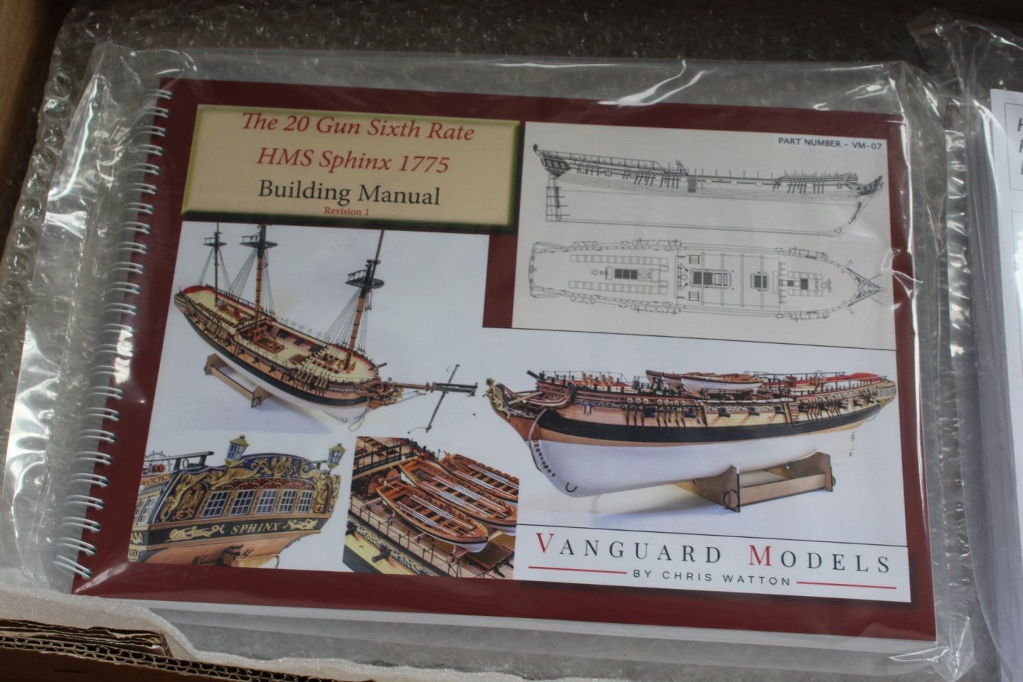
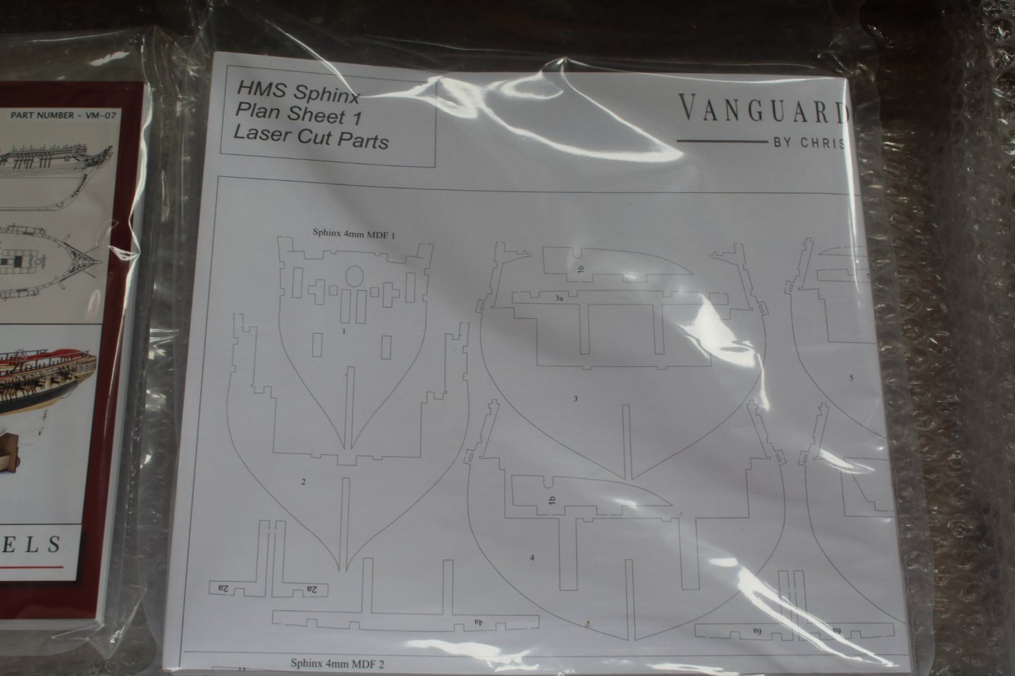
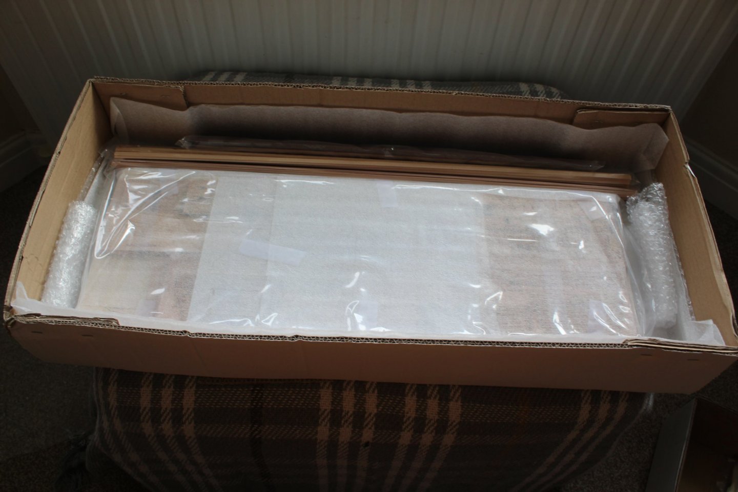
KIT DELIVERED The pre ordered HMS Sphinx kit has now arrived and I am now really looking forward to starting the build. The prototype kit built by James Hatch looks amazing and is the build standard I would like to aspire to. I downloaded on-line build manual earlier this month in eager anticipation of receiving the kit and I spent many hours getting familiar with the build processes and, where necessary, adding to my tool and paint collection. I plan to take my time with this build (which will be a first for me!). I have started a build log, which will show how I have implemented the information contained in the building manual (rev 1) and the 23 off plan sheets. I will also share any tips, problems, etc. which may help others with their build. The kit was well packaged and protected There was a little bit of transit damage to the box, but the kit was so well packed and protected there were no problems with the kit once the box was opened. An example of the protection A very nice touch, a HMS Sphinx coaster The pear wood fitting (an optional extra) The manual looks very good The plan sheets are very well presented More layers of protection LINK TO MY BUILD LOG

-
Looks like I'm going nowhere on Tuesday. 😀

-
Fingers crossed you get a big delivery of printed material today😀
- 355 replies
-
- 3
-

-
- vanguard models
- Sphinx
- (and 1 more)
-
I have started my HMS Sphinx build log as a word document to explain (to myself) how I plan to tackle the various stages.
- 857 replies
-
- 5
-
-
- Sphinx
- Vanguard Models
- (and 1 more)
-
Thanks Bruce Ordered from them
-
I have spent a bit of time trying to get use to using the new camera together with some photo editing software. There is so much to learn and I know I have only scratched the surface but I am amazed at what can be done. Many thanks to Tim and Glenn (USA) for their help. This was a picture I took and is the standard jpg file direct from the camera With this version of the same photo I have taken the raw file from the camera and applied a few effects. I have added a bit of everything that Adobe Lightroom can offer so I can could get an idea of what each control does. No doubt I have gone a tad overboard with the effects but nonetheless the results are, to a novice like me, staggering.
-
Great news, looking forward to making a start next week
- 355 replies
-
- 1
-
-
- vanguard models
- Sphinx
- (and 1 more)
-
Just been looking I would like to buy one but I would prefer to purchase from a UK supplier which does not seem to be available. Shipping to UK is also almost costs the same as the tool, seems expensive.
-
Having spent some time reading the manual and James's build log the HMS Sphinx build is very well explained, the photos really help also. My initial impression is this will probably be a time consuming project for me, maybe 9 to 12 months, but hopfully it will be relatively problem free. There are a couple of build items I'm not sure about at the moment but I hoping once the kit arrives all will become clear.😀
-
Looks good. My local model shop model shop gave me the inside track on the super phalic telling me its like a wood glue with ca grab properties.
-
Perfect timing for me, as I'm away from home until Saturday.
-
@chris watton much deserved success with the Sphinx venture. The standard of your previous kits proved without doubt your designs are cut above the others. The work undertaken by @James H in support aldo shows what is possible to build by mere mortals like me.
-
Ditto. Interesting to see that the first planking at stern was finished short of the stern post which avoids sanding the false keel thinner with a beading line.