


Beef Wellington
-
Posts
2,245 -
Joined
-
Last visited
Reputation Activity
-

 Beef Wellington got a reaction from Canute in HMS Sphinx 1775 by mtaylor - FINISHED - Vanguard Models - 1:64
Looking forward to this Mark, I've always had you down as a scratch only builder but am sure this will be a fun project.
-
 Beef Wellington got a reaction from Edwardkenway in HMS Sphinx 1775 by mtaylor - FINISHED - Vanguard Models - 1:64
Looking forward to this Mark, I've always had you down as a scratch only builder but am sure this will be a fun project.
-
 Beef Wellington reacted to thibaultron in HMS Granado Cross Section by thibaultron - CAF Models - 1/48th - First POF Model
Part 010
Next I removed the resin inserts and trimmed off the heads, then reinstalled the tail pieces.
I installed the larger of the blocks that tie the tips of the two halves together.
Then I installed the thin piece, that goes below it. This is a laser cut plywood piece, and I had to sand bevels on each end so that they could slide into the groves in the frame.
At this point I noticed that I had not sanded them enough and they had spread the frames a little (see the above picture). By that point, however, the glue had dried enough to prevent me removing them! I’ll have to break out my Jewelers Saw and cut through the center, which will hopefully remove enough so that the frames close up properly.
Meanwhile, I cut the chocks down to match the level of the respective frame members. The photograph shows one chock cut and sanded (right hand side), while I have just started on the second one. For this I used an X-Acto Number 2 blade, small files, and fingernail sanding sticks. After the chocks passed the fingernail test (a fingernail passed across the surface does not catch on any protrusions at the joints of the surfaces), I sanded along the grain to hide the marks made cutting out the piece.
After finishing the chocks on this side, I flipped the frame over and did the same to the ones on that side.
I then used the saw to split the plywood pieces, On one side the plywood fell out as I was completing the cut. I glued the two sections back together and reinserted them. In the picture below you can see them right after I got them back in.
I took a pair of flat surface needle nose pliers and used them to hold the two plywood sections into a flat alignment top and bottom (you can see that they are not aligned in the picture above).
Once the glue had dried I faired the ends of the plywood pieces and the blocks above them down even with the frame surfaces. I also filed the top and bottoms of the plywood inserts to insure that those surfaces were lined up correctly.
I managed to pop one of the other joints in the frame while doing this, but in the end, I finally finished this frame!
Next I started to look around for something to store the frames in, as I finished them. In the end I found a simple, cheap, way to do this. I had a beat up one of the small Post Office Flat Rate Boxes laying around and when I folded it up, it was an ideal size.
The box is designed to be held together, once folded up, when the tab on the top is glued to the front of the box. As I was going the not glue the top down, I glued the corner tabs in place then folded the side ears down and glued them also. After cutting the ears off the sides of the top, I had a nice frame holder! It is large enough to hold two frames in each layer, if the second frame is set in upside down so that the bottom of the frame spans over one tip of the first. It looks to be deep enough for three layers (6 frames total) of frames per box.
At this point, in time, I have also finished Frame 7, and will detail that in the next part. Before starting on the next two frames (7 & 8), there are corrections to the instructions needed, so stay tuned, (or go to John H’s review of this kit, where he details the corrections)!
-
Beef Wellington reacted to thibaultron in HMS Granado Cross Section by thibaultron - CAF Models - 1/48th - First POF Model
Part 009
Next I had to clean out the inside corners of the upper piece for the slots for the false keel, keel, and chocks, to remove the rounded corners left by the milling bit.
After further cleaning up the false keel, I used it and the keel to check my progress on cutting out the corners.
Next I used the false keel as a jig to align the upper and lower frame slots, and glued the upper section in place, then removed the false keel and placed weights on the upper section and along the exposed lower half to keep everything level while the glue dried.
Next came a step that should have been in the instructions, before the frame assembly. There is a temporary resin fill piece between the upper and lower halves of the frame, that positions the upper tips of the frame pieces, away from each other. After the frame is glued, two small pieces of wood span areas of this gap, and form part of the finished frame. The only reference to this is the graphic of assembling the upper half, were it is shown in place between the frame sections.
This shows the two pieces that will be installed when the inserts are removed.
The entire upper tip piece will stand proud, of the lower frame half, held in place only by the chock and the two inserts, once the frame is finished. After I install the two wooden support pieces, I’ll trim the head off the insert, and reinstall the tail piece, to support the gap, until I reach a point where it is no longer needed.
The problem, is that both the upper and lower tip pieces have to be fitted to the resin piece, just like the chocks and keel parts. With the lower half assembled this proved awkward.
One thing to be aware of, is that the groves are angled, not straight across the frame section. Yes, I didn’t notice this on the first two pieces. The resin piece required minor cleanup to remove some small vent nubs along the flat tail piece.
This is a picture of one side cut to fit the insert, and the other before I started.
Here is both sides fitted.
Notice that the lower frame half tip (the upper one in this shot) “re-kitted” itself during the process. The same thing happened on the other side.
So, after fitting the parts, I reattached the two lower frame pieces, and, after the glue dried, proceeded to glue one of the upper pieces in place. I shortened the tail piece of the resin spacer a little, to make sure that it was not hitting the adjacent frame section. I found that modified clothes pins had just the right spacing to clamp the parts parallel. I reversed the spring so that the handle ends were the side closed by the spring pressure (see the photos). I used a clamp on either side of the chock, and at the top of the frame to hold the tips in line. I used a file to add weight to hold the tips tight to the insert.
This method does not normally work on a single chock holding two frame sections as the pressure tends to push the parts away from each other. For this use though, everything is locked in place by the insert and the previously glued sections, and the clamp ends are spaced by the lower frame surfaces.
Yes, the third photograph shows a nice lump of excess glue at the chock, but that end of the chock will be filed down to match the frame section, which is thinner than the mating end of the tip piece. If you look at the joint to the right in that picture, you will see that the same thing will have to be done to one side of that chock, also.
The forum software only allows a maximum of 16 pictures per post, so I will continue when I get a bit further along is completing this frame.
-
Beef Wellington reacted to thibaultron in HMS Granado Cross Section by thibaultron - CAF Models - 1/48th - First POF Model
Part 008, or “How to continue to do it wrong!”
During the build, I will continue to show mistakes, why I made them, and (Hopefully) how I fixed them. This is my first POF build, and basically my first wood sailing ship kit, though I have built HO scale wood buildings and wood RC warships. By showing my mistakes, I may help others avoid them. “Good judgement comes from experience, experience comes from bad judgement. "
In retrospect, I should have started with one of the inside frames, where mistakes could have been more easily hidden.
As I mentioned before, Frame 6 would not fit back between the shims when I tried to put it back into place. After getting everything un-glued, I rebuilt the lower section of the frame first, so far so good. Then, I said to myself, “Self, you know this frame has to fit onto the keel, doesn’t it?”. Self replied, “You’re right, better try that!"
So I found the two pieces for the keel, the keel, and false keel. The first thing I found was that both pieces had been machined incorrectly!!
As you can see above, the blank apparently shifted a little when they turned it over to mill the back, and the upper and lower surfaces came out misaligned. Not by much, but after cleanup both the parts were too short by twice the difference in misalignment (had to correct both top and bottom). At least the relative depth of the lands on the false keel are correct. So, I thought, “I can just add a shim between the keel and false keel, to make up the difference.” Looking at the keel. I then discovered that the two rabbets are now also misaligned, height wise, and the keel will sit lower in the assembly jig. Not good! I’m going to write to CAF, and see if they will replace these two parts. Luckily, these were the only parts in that blank.
After some cleanup it looked like this,
Now, to continue the frame 6 story, it turns out that, no, the keel would not fit in the frame slot! ********!! I tried widening the slot with files, etc., but was just marking up the underside of the chock, and cutting the frame piece unsquarely. So, out came the Isopropyl alcohol again!
I cleaned up the unsquared area with my disk sander and got everything put back together, with the keel now fitting nicely. Then, for fun, I cutout the bottom piece of the upper half of the frame, and placed it on top of the lower pieces. Double *******! The lower frame curve was too shallow! So once again, do over.
If you look closely you can see that the front assembly, does not have the same curve as the back piece (6A-6A-1). Note however how nicely the edges of the wider sections match. Sigh.
I cleaned up the outside surfaces of the upper piece to remove the attachment points.
As can be seen in the above picture, I then applied tape to the mating surface of the part, to prevent it from sticking to the lower pieces.
Then I glued the lower pieces in place and clamped the upper piece in place to align them. I had to sand the wedge areas of the chock to lengthen it to fill the longer gap between the two frames. There is enough meat in the part to do this.
After everything was correctly positioned I clamped the upper section to the lower ones, until the glue had grabbed, then removed the upper section, and placed a weight on the lower parts, to keep them flat.
Finally I got the two curves to match, unfortunately, now the keel slot in the bottom half is too wide. Also unfortunately this frame is an end frame, and, naturally, the exposed side. I’ll figure out that problem later.
Here is a picture with the bottom section glued back together, and the upper piece set on top. Now the curves match! And, also now, the slots in the lower half are wider than the ones in the upper section.
After everything had dried, I glued the rest of the lower Frame 6 parts in place. Finally done with this assembly!
-
Beef Wellington reacted to druxey in Le Rochefort by No Idea - 1/24th Scale - First POF Build
Just lovely, If you are planning on wire wool, try to get bronze not steel. Steel will leave tiny particles that will eventually form rust spots.
-
Beef Wellington reacted to No Idea in Le Rochefort by No Idea - 1/24th Scale - First POF Build
Hi Everyone
I've now faired the inside of the hull which really does take hours. My hands and fingers are killing me they are so sore 😂 I wouldn't mind but I was using blocks too!!! I have learnt not to leave any frame chocks protruding too far into the hull; thats another one for next time too! I didn't have many places where I needed to remove too much material. It was more about lining the frames up correctly - please remember though I do have scale on my side as these frames are thick. How you builders do this at 1/48 scale must make the process so much harder and more precise in the first place.
I have to say its a lovely job to do especially when you get down to some finer papers such as 320 and 400 grit. You can just feel that things are starting to be right - it's hard to explain. I've stopped at 400 grit as I'm sure that the interior is going to get a bit bashed around before it needs a final finish.
I'm not sure what you all use for a final finish but I'm thinking wire wool is probably the way to go when I get around to that stage.
The next job is to make the keelson and I will make a start on that tricky piece next weekend.
Mark - BTW I think I should say thanks for all of the likes too its quite humbling to be honest.
-
 Beef Wellington got a reaction from BANYAN in HMS Jason by Beef Wellington - Caldercraft - 1:64 - Artois-class frigate modified from HMS Diana 1794
Finding a little time to update some (small) progress, thanks everyone for the interest, comments and likes.
@Eamonn, @Mike - One comment off the bat, certainly would not want to be claiming this approach as my own. I think we all stand on the shoulders of others, and it was Rob's Ethalion build that inspired me to try this approach...how's it going? Read on....
Before pressing forward with the deck, I had to decide how the companionway cover would sit. While not being quite sure how much would be visible through the tiny windows, the decision was made to once again install some false beams and carlings for the companion cover to sit on. This sits quite nicely in place, and is once again put aside for final detailing.
Jumping into planking proper, it quickly became clear that initial steps required a bit of fine tuning. Once the various coaming are glued into position, quite a bit of care is needed to ensure alignment to the centerline, and also address any potential symmetry issues. It was necessary to re-attach the rear hatch coaming as it was clear that this was slightly off-center and the misalignment would have been emphasized by the run of the planks. The only other slight complication was the need to cut custom planks to flank the hatchway, capstan step and rear grate coamings. Not difficult, just time consuming to ensure a fit and keep the necessary curvature for the run of the planks.
Overall, pretty happy with how this is turning out. The only other thing to comment on is that the decision was made to plank the top-tackle and pump scuttles which seems more consistent with the original plans, rather than the raised gratings suggested by the kit.
Note - The planking lines drawn onto the subdeck are not 100% accurate, and they're there just to help plan the butt-shift and get a better sense for the how the alignment will eventually run into the waterway. There's also a little bit of pencil lead smudging from the caulking which always seems unavoidable and hasn't been cleaned up yet...
-
Beef Wellington reacted to Richard44 in HMS Pegasus by Richard44 - FINISHED - Amati/Victory Models - 1:64
Thanks for the likes.
The kit supplies gangways which extend from the quarterdeck forward for a short distance. I decided to follow TFFM and add gangboards which will run from the end of the gangways to the foredeck. There are several consequences to this decision - the gangways have to be raised a few mm so that they are very slightly above the level of the cap rail in the waist, the two ladders leading from the upper deck to the foredeck are no longer required, there is no mention in TFFM of hammock cranes along the cap rail in the waist so these will be omitted, and there are stanchions along the waist cap rail now with a rough tree rail on top.
The photo shows the supplied ply gangway held in place as per the instructions.
The gangway needed to be raised, which required trimming of the aft end so that it would fit flush against the quarterdeck breast beam rather than being below it. The ply also needs to be faced with planks. If I’d used the ply, I would have had to hide it’s exposed edge, so rather than do this, I made new gangways of edge joined planks. I didn’t think that simple edge gluing of the gangway against the bulwark was going to work very well, especially as the gangway is supposed to be slightly higher than the cap rail, so I added two blocks on the underside of the gangway to give a much larger gluing area. The photo shows the new gangways, trimmed to fit, with the knee and blocks. Only one knee is shown in TFFM, not the two supplied in the kit.
The new gangways in place.
The gangboards were made by edge gluing two, pre-bent, planks together. Four knees are supposed to support the gangboards, but in spite of several attempts,I couldn’t get these in place, so resorted to Plan B - gluing small blocks along the edge of the boards and then gluing the boards to the bulwarks. Fixing the knees in place would have been very easy if I had planned on adding the gangboards early in the build. The blocks are not visible, and I don’t think the knees would have been either.
So, the gangways/gangboards are in place.
Cheers
-
Beef Wellington reacted to Siggi52 in HMS Tiger 1747 by Siggi52 - 1:48 - 60 gun ship from NMM plans
Hello,
because the summer is gone here, since 4 weeks we have temperatures only around 20°C and every day rain 🙁, I decided that I should be better busy at the shipyard. So I started painting the starboard side. The first half is done 😓
-
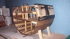
Beef Wellington reacted to Blue Ensign in HMS Sphinx 1775 by Blue Ensign - FINISHED - Vanguard Models - 1:64 scale
Post Six
Stern and bow patterns.
I wasn’t too keen on working the bow and stern patterns off-model, particularly the stern.
As it happens, for the bow pattern the off-model option was removed; unlike the bow pattern bulkhead which wouldn’t shift after fitting the patterns.
It slid on ok and I was careful not to allow glue onto the keel, but move it would not and I had the nightmare vision of snapping the false keel which at only 3mm wide and quite long is very vulnerable at this stage.
So, on-model fairing it will be.
For preliminary fairing of the stern pattern I am using 10mm and 20mm Finger sanders, initially with coarse grade paper.
It is worth slipping a couple of lengths of waste strip from the keel fret between the stern patterns to support them during sanding, particularly parts 24.
One of mine fell off during sanding, probably due to insufficient glue used to avoid sticking it to the keel.
3816(2)
So, this is as far as I felt comfortable with off-model fairing.
3825(2)
3819(2)
3826(2)
All Bulkheads glued into place now.
3812
Only been four days and look at the state of my working area, think I need a general tidy up.
B.E.
28/08/21
-
Beef Wellington reacted to Louie da fly in Ancient galley rams discovered - photos
Ancient vessels were built "shell-first" - either without frames or with frames added after the planking was completed, and the planks were held together with tenons in mortises within adjoining planks, pinned in place with dowels.
(from https://en.wikipedia.org/wiki/Phoenician_joints )
According to Prof John Pryor's book Age of the Dromon the waterline ram was designed to break the tenons so the planks separated, letting the water in. Later (mediaeval) ships were built frame-first, and it is believed this structure was too strong for the waterline ram to have the same effect, and the "ram" moved upward to become a "spur", which it is proposed was intended either to capsize the enemy vessel or break its oars (or perhaps both).
I suppose the test model(s) will be constructed the first way.
Steven
-
Beef Wellington reacted to Timmo in HMS Jason by Beef Wellington - Caldercraft - 1:64 - Artois-class frigate modified from HMS Diana 1794
That’s great work and a string of very educational posts Jason. Glad to see her back underway.
The spreadsheet idea seems so obvious and is something I’ll store away for future.
Coincidentally I’ve been fitting decking to a 1:1 scale sailing dinghy and spent a day working out tapers and spacing for a measly five planks.
-
 Beef Wellington got a reaction from Jorge Diaz O in HMS Jason by Beef Wellington - Caldercraft - 1:64 - Artois-class frigate modified from HMS Diana 1794
Thanks everyone as always for continued interest....
Jim - not going to be able to put canon rigging off much longer....ugghh
The area around and immediately aft of the pumps is really quite congested and requires some planning. The main jeer and topsail sheet bitts were scratched, parts from the kit look a little oversize to my eye. Pillars were made square in section after studying as many pictures as I could find, these seem to be a mix between square and round, but I don't think my turning skills are up to making round ones. Side blocks and fake sheaves were also added.
For the aftermost stanchions, I followed the AOTS diagrams which shows these to be of smaller dimension. All of these items will require some final finishing. The capstan step was cut out of a single piece of 2mm boxwood and 'joints' faked by scoring with a knife and filling with pencil lead. This took a while with just hand tools and I couldn't help but think of a toilet seat from the end result! These details will be visible but obscured so forcing myself not to be too fussy. The base of the capstan itself as sanded back to the pawl rim which sits in the hole in the capstan step. (This requires a lot more finishing to get the surface to be acceptable)
Pictures are hopefully self explanatory. I've shaped some box for the elm tree pump shafts and I've placed an offcut just to get a sense for positioning....
And to mystery that's been puzzling me for a while (and Rob alludes to in his Ethalion log), how does the placement of the pump brakes reconcile in the this workspace in such close proximity to the capstan and companion?
I seem to recall reading 'somewhere' that some stanchions were removeable which would explain the location around the capstan - once both sets were removed this would make this workable. In later ships, these seem to have been replaced by hinged iron columns which makes a lot of sense. if anyone could corroborate that would be much appreciated! Lastly, given the pump brakes also extend to this area, these would really be a permanent accident waiting to happen at the foot of the ladder to the quarterdeck which must have received quite a bit of use. I can't find any reference to this, bit I have to suspect that pump brakes were removeable, and unshipped when not in use. On the Artios class, there is a set forward, and 2 sets aft - in normal seagoing routine I would speculate that not all banks would have been needed, but could easily have been placed in the event or expectation of an emergency. The last photo below from Victory seems to show exactly this, and it also makes the square section joining each brake much more functional. Again, if anyone can point me to sources would be much appreciated!
-
Beef Wellington got a reaction from Jorge Diaz O in HMS Jason by Beef Wellington - Caldercraft - 1:64 - Artois-class frigate modified from HMS Diana 1794
Cheers Gents, appreciate the support, comments and likes...
Welcome aboard Ian 🙂
A rather dreary rainy day precluded any other activities so as able get a decent amount of time in. Spent most of the day completing the cannon carriages, these really are incredibly time consuming and seemingly never ending, but can now report are complete. I did decide to cheat a little on those carriages that will be mostly obscured away from the waist. Rather than continuing to use the pins to simulate bolts which are incredibly fiddly, the carriage bolts were simulated using a fine tip black pen and then touch of dark iron paint to tone it down. Pins have been used on all the carriages that will mount in or immediately about the waist. The macro photo below shows the 'real' bolts in the foreground and the 'cheat' in the rear. At real life viewing distance these are difficult to tell apart if you didn't know - the difference really being the lack of about 8hrs of cursing.
Experimentation with the cap squares and royal cyphers next...
-
 Beef Wellington got a reaction from mtaylor in HMS Enterprize by Timmo - 1/36 scale - RADIO - 28-gun frigate
Hi Wayne, embarrassed to say I've just stumbled across your log, curse this site for just having too much great content. Hoping you've kept up the progress, the masts look fantastic, and Harrier is in a class of her own. Cute dogs as well!
-
Beef Wellington got a reaction from Jorge Diaz O in HMS Jason by Beef Wellington - Caldercraft - 1:64 - Artois-class frigate modified from HMS Diana 1794
Hi Folks,
Sadly been rather absent from both the shipyard and this site for some time. I very much hope to catch up soon on everyone else's fine builds here soon. Time to get a little more up to date, the cutter is pretty close to completion aside from a little fettling.
Frames were added to the interior using strips cut from some scrap 0.5mm pear wood. These were soaked and pre-bent in situ prior to gluing with PVA:
The frames were further reduced down to the keel former to try and get a bit more depth the boat. To my eye, applying planking to the false deck puts the board too high, especially as there is very little room to play with considering the various structural elements still to go on. A template for the footwaling was then made up to determine the shape. Once the placement was determined, the rising plank was added (again cut from some 0.5mm pear sheet)
I wanted to try and allow the footwalling to have an element of curvature which would be natural on the real boat. A relatively straightforward way to achieve this was to apply wood strip to thin card to match the template which maintains a lot of flexibility (Straight strip was used rather than the more complicated curved planking on the plan). Once dry, the assembly was easily glued on top of the keel former, the footwaling then follows the interior curve naturally.
With those element in place, it was possible to add the platform under the sternsheets. The Diana plans show these as a grating, but to my eye again the kit supplied grating is too large, so plain boards were installed instead which also appear to be used. After the main and fore mast steps, thwarts and ringbolts I assume would be used for hoisting the boat had been added, the bow was closed in using a cover as suggested on the plan - this also helped disguise the rudimentary construction at the bow. The rowlocks were cut, interestingly these are not symetrical between port and starboard, and one seems to sit rather awkwardly in the sternsheets.
The sternsheets were made up and installed, again having used a template to finalise shape, together with all the other details including mast thwarts, gunwale and knees.
The colour scheme follows a slightly simplified version of that shown below which seems suitably utilitarian. Looking at this, and comparing once the black was applied, suggests to me that I made a mistake in the tapering of the clinker planking. The black area covers both the wash strake and upper strake, and judging from these pictures it appears that these are of somewhat consistent in width, especially toward the stem. I had tapered these proportionally as well, hoping nobody else notices...
-
 Beef Wellington got a reaction from rcweir in HMS Jason by Beef Wellington - Caldercraft - 1:64 - Artois-class frigate modified from HMS Diana 1794
@mugje - just to be clear, the resin hull shown is an 'aftermarket' mini-kit supplied by caldercraft, its not included in the kit. What I'm attempting to do is leverage the kit supplied items as best I can.
Cutter Progress: Part 2
Keel and bow section was cut out of some spare wood and glued in place, and once the basic hull was completed, a decision was needed on how to add a second layer of planking, kit instructions specify to use another layer of 0.5mm walnut. I really wanted to try and replicate the clinker hull planking shown in the AOTS Diana book, and to do this a used some cardstock instead of wood to cut individual strakes. Fist challenge was to determine the width of each plank on the hull. This was done using 'tick strips' at about 10 points along the hull. The lowest (non-clinkered) garboard strake was simply omitted. The end of the cardstock strips were cut down (rather than truly tapered) to allow the planking to terminate smoothly at the front bow and stern which is how I believe the planking is done in practice. Each strip was cut to about 2.5mm thickness, the benefit of cardstock is that when coated with dilute PVA glue it becomes very manageable and can simply be bent to shape rather than the spiling that would have been necessary if wood had been used.
Once the hull had been marked out to 'prove' the planking separation, these were not referenced again. Once a strip had been installed, the lowest point of the next strip was placed using the tickstrips. This process was simply repeated, with time allowed for the glue to dry sufficiently for the surface to harden. Dilute PVA was used quite liberally to ensure a good bond between the wood and card as the hope is for this to add additional structural strength.
The final 2 strakes were completed with one wider strip as the uppermost strake is non-clinkered and would not be visible. Extra height was added for safety as this can be easily cut back once glue has dried.
Once both sides had been completed, each was given a few more coats of dilute PVA for added insurance....why not?! With the exterior planking work completed, attention could be turned to the interior and the potentially catastrophic step of removing the frames. This actually went smoothly, but has to be approached with patience and a light hand. The kit base was removed as well as the actual flooring should be a little lower I feel. The frames were cut back a little more than is perhaps necessary, but this will allow flexibility as to where the floor is, and hopefully prevent them from being seen. Practically, it also allowed the interior planking to be sanded more effectively. The hull in this state clearly needs a light hand, but is surprisingly robust despite my fears.
Once an initial sanding had been completed, some light wood filler was used to fill imperfections and deal with some of the slight clinkering of the topmost walnut strips. Once sanded back, dilute PVA was once again brushed on....yes, paranoia perhaps, but can't hurt.
Finally I was able to add an initial coat of white point to the hull to get a better idea of how this turned out (In this case Valejo 'off white' as it was all I could get from Amazon in a reasonable timeframe). This highlighted that some finish work will be required in some areas where the eye is drawn to surface imperfections, but one thing I've learned is that the cardstock planks can be effectively sanded, probably due to the application of dilute PVA glue. Definitely some fine tuning still needed and far from perfect, but its hard not to be pleased with the result for a first attempt.
-
Beef Wellington reacted to Timmo in HMS Enterprize by Timmo - 1/36 scale - RADIO - 28-gun frigate
go on then, another one...
The ominous torpedo ballast keel is visible when in the pool, unlike local lakes etc. I'm interested to see whether Enterprise's greater hull capacity and bouyancy will allow a bit more internal ballast and something that will be less yacht-like underneath her.
-
Beef Wellington got a reaction from Jorge Diaz O in HMS Jason by Beef Wellington - Caldercraft - 1:64 - Artois-class frigate modified from HMS Diana 1794
Cheers gents,
Small update reflecting this weekend's work. Have been unsure what to do with the fore companion ladder and whether to include the safety lines and whether these would look right, but approaching point where decision is needed. I seem to recall reading in TFFM that the hand ropes would have been secured to small ringbolts in the deck below (there really should be a word for the situation where you remember reading something but then are subsequently unable to find the reference when actually needed!). Small PE ring bolts were used in the lower deck and 0.3mm line secured to them with a false splice. RB Models stanchions were used as they seemed a little more to scale, rather than the kit supplied items which appeared too tall - these may not be completely period accurate, but are close enough to my eye.
I feel there should also be something around the main hatch companion ladder, but cant quite see what this would look like, as the iron supports for the pumps are obstructions.
The only way I could figure out to install these was to estimate the length of line needed and then attach the ringbolts off the model to - I was anticipating many redoes here but luckily seemed to get it how I was hoping on the first attempt. The location of the ringbolts was determined by dry fitting the companion ladder, the ladder only being finally installed once the hand ropes were all in position.
-
Beef Wellington got a reaction from mtaylor in hatch over a ladderway
Is there anything that suggests this shows anything other than a simple dual coaming structure, the steam scuttle above stove, and the adjoining forward one for the chimney structure. The dotted line just seem to represent the beam separating these (?). There seem to be many slightly different representations on models of the chimney surround being a wooden or iron structure sitting in the coaming.
-
Beef Wellington reacted to dunnock in HMS Diana by dunnock - FINISHED - Caldercraft - 1:64
A few days away again, this time in Kent for a bit of bird watching but mainly to visit Chatham Dockyard. The talk and tour of the ropery was fascinating. In the early days, before the process was mechanised, how they twisted the initial yarn by hand from a coil of fibre wrapped around the waist is remarkable. It seems that it was fairly late on in the 19th century that rope making caught up with the the textile industry where mechanisation of similar spinning processes had begun to be used nearly 100 years earlier.
A few other pieces completed between continuing with the stern galleries.
I had some trouble with the steps getting the spacing to appear correct. On the first attempt I didn’t like the arrangement so removed them and tried again. I’m much happier with the new alignment and also made some attempt to allow for the tumblehome and shape of the wales.
I have also made the riders. Although only the two amidships will be visible, I have also made the three that go along the aft section but which will be hidden by the quarter deck. They are shaped and painted ready to be fitted.
The kit-supplied rudder no longer fits because of the new stern post replacement. I cut another from boxwood sheet using a template taken from AotS Diana. A bit more tapering is required but generally I’m happy with the overall look.
Back to the quarter galleries. I glazed the lights using the polyester film supplied and then backed the false lights with black card before glueing the frame to the top and bottom patterns. This gave me the base from which to shape the lower finishing pieces. These are made from 7mm boxwood sheet and a piece of 2mm walnut taken from the kit. I have tried to follow the general shape illustrated in the AotS. The starboard gallery is finished for the moment, with just the drop to make, but I expect that a small amount of further work will be needed when they come to be fitted permanently
The port quarter gallery will follow the same pattern and will probably take the rest of the weekend...
-
-
Beef Wellington reacted to RGL in USS Langley by RGL - FINISHED - Trumpeter - 1/350 - PLASTIC
The Trumpeter kit for uses the netting in 2 pieces and some ridiculous flimsy arms to hold them, and Eduard provides something better with really **** poor instructions,
the net needs to be bent to about 80degrees
then it needs a rivet strip among side the top to reflect the real things.
-
Beef Wellington reacted to robdurant in Barque Stefano by robdurant - MarisStella - 1:63
Starboard side plated....
A few more in progress shots, then the finished starboard side.
The keen-eyed among you will spot a patch where I did a bit of cleaning of one of the plates... It should blend in again over time.